

Инновационные процессы в исследовательской и образовательной деятел
..pdfSteel grade |
|
|
|
|
Elements content, % |
|
|
|
||||
C |
Si |
Mn |
Cr |
|
Ni |
V |
Nb |
Mo |
Cu |
S |
P |
|
|
|
|||||||||||
15Х2Г2НМФБ |
0,15 |
0,31 |
2,07 |
2,39 |
|
1,48 |
0,14 |
0,07 |
0,53 |
0,19 |
0,008 |
0,016 |
|
|
|
|
|
|
|
|
|
|
|
|
|
Experimental results and discussion
Quenching was performed under the intercritical temperature range (ITR) in the original state, the average grain size was 10–15 microns, hardness 42 HRC. Heat Treatment was carried out in a laboratory chamber furnace. Hotrolled LCMS samples of 15H2G2NMFB (15Х2Г2НМФБ) were austenized in the intercritical temperature range (quenching temperature of 810 °C), with the soaking time of 30 minutes and cooling in water or air. The presence of strong carbide forming elements provides dispersed austenite original structure (Fig. 1), with LCMS grain size of 10–15 mkm.
Fig. 1. The initial grain structure of 15H2G2NMFB steel samples
a – quenching in water |
b – quenching in air |
Fig. 2 Quenching of НМС 15H2G2NMFB steel samples in the intercritical temperature range (810 °С) for 30 minutes
After hardening the LCMS structure comprised mainly lath martensite regardless of the cooling medium, Figure 2. High dislocation density in lath martensite and dispersion of the typical elements of the lath structure caused a high level of strength and mobility resulted in increased relaxation capability [3]. The high level of ductility and toughness was caused by the absence of per-
11
lite transformation products and upper bainite. Lower bainite (if it was present in the structure) provided a somewhat lower viscosity than the particulate lath martensite, but the mixture of martensite and lower bainite allowed to obtain the highest values of viscosity. The properties depended on the austenitization temperature and the cooling rate. Usually, the cooling medium little influences the LCMS strength so preference is usually given to the air cooling. Values of ductility and toughness (KCV) after the air cooling were significantly higher than after cooling in water.
In general, after air hardening in the intercritical temperature range the mechanical properties obtained approximately corresponded to the upper range of values after hardening from the temperature of 980 °C and tempering.
Conclusions
1.Preservation of the lath martensite structure in the interphase region
(ITR) makes it possible to get lath martensite structure in α- phase by heating the LCMS 15H2G2NMFB (15Х2Г2НМФБ) below the Ac3, which allows to quench in the interphase region. Regardless of the cooling medium, hardening always results in mainly lath martensite.
2.The combination of strength, ductility and toughness achieved in the hardened LCMS 15H2G2NMFB (15Х2Г2НМФБ) indicates the possibility of replacing the complete quenching (980 °C) with quenching in the upper temperature range (810 °C).
References
1.Азотирование и карбонитрирование / Р. Чаттерджи–Фишер, Ф.В. Эйзелл [и др.]; пер. с нем. под ред. А.В. Супова. – М.: Металлургия, 1990. – 280 с.
2.Ларинин Д.М., Клейнер Л.М., Шацов А.А. Конструкционная прочность низкоуглеродистой мартенситной стали 12Х2Г2МНФБ // МиТОМ. – 2010. – № 11. – С. 34–38.
3.Клейнер Л.М., Шацов А.А. Нанокристаллическая структура низкоуглеродистого реечного мартенсита и конструкционная прочность // Фундаментальные проблемы современного материаловедения. – 2007. – Т. 4,
№1. – С. 72–75.
12

R.V. Vikhorev
Perm National Research Polytechnic University
IMPLEMENTATION OF SYSTEMS OF LOGIC FUNCTIONS
BASED ON LUT FPGA
It is proposed LUT implements a system of m logic functions – DC – LUT, and the realization of alternations constituents provided structure is similar to setting interconnection.
Key words: Logic functions, LUT, FPGA.
Introduction
Logic cell (Logic Cell) FPGA, often called LUT (Look Up Table LUT – truth table) is made on the basis of the multiplexer, which is being built as a tree of elementary multiplexers 2–1 on the basis of the transmission MOS transistors, data inputs which are adjusted so configurable cells called static memory SRAM [1]. Downloading a configuration SRAM memory values truth table logic function of n variables can realize any function, including constants.
The standard number of inputs (ROM address inputs) is generally equal to four, but modern “advanced” FPGAs are complex, tunable LUT with the number of inputs of 6, 7, for example [2, 3, 4]. There are reports on the number of LUT inputs to 8.
Logic element DC-LUT
As you know, CMOS transistors used in the LUT at the same topological characteristics of the source and drain of transistors actually equivalent. Transistor circuit, “inverse” structure of LUT can be obtained by “turning” LUT 180 degrees [5, 6] – Figure 1.
X2 |
X1 |
Z3
Z2
Z1
Z0
Fig. 1. Transistor circuits – decoder DC – LUT
13

Modeling logic element for the implementation of systems of logic functions with the refined block diagram alternation constituents logic function
The modeling of the logic element for the implementation of systems of logic functions with the refined block diagram alternation constituents logic function for n = 2 (Fig. 2) in the circuit simulation NI Multisim 10 firm National Instruments Electronics Workbench Group.
Fig. 2. The gate fo r the implementation of systems of logic functions with the refined block diagram alternation constituents logic function for n = 2
14
Transistor gates control unit alternations carried inverters installed downstream “unwrapped”, in relation to the classical LUT, wood transistors.
And the alternative chain with no activation pathways in the tree provide a supply of a logical unit. Figure 2 contains the setting for the implementation of the function “exclusive OR” – the LED on the output of the OR as variables X1, X2 different meaning.
The simulation confirms the efficiency of the proposed technical solutions to specified block alternations constituents DC – LUT.
Conclusion
Thus, the structure of the proposed modified decoder logic element – DC LUT to implement the system functions in the FPGA type FPGA, which is based on a tree diagram in transmitting MOS transistors. Specified block structure alternations constituents, taking into account the requirements of the activation of only one path in the circuit.
In the modified scheme, the signals from the modified tree transistors DC come to the gates of the MOS transistor unit alternations, and configuration information from the configuration memory is supplied to the drains of the transistors.
The simulation system of circuit simulation NI Multisim 10 firm National Instruments Electronics Workbench Group confirms the efficiency of the proposed new technical solutions DC – LUT.
References
1.Цыбин C. Программируемая коммутация ПЛИС: взгляд изнутри [Электронный ресурс]. – URL: http://www.kit-e.ru/articles/plis/2010_11_56.php
(дата обращения: 16.12.2014).
2.Самкова Е. Stratix IV против Virtex-5. Точка не поставлена [Электронный ресурс]. – URL: http://www.russianelectronics.ru/leader- r/review/2189/doc/46576/ (дата обращения 16.01.15).
3.Aria II GX. Altera [Электронный ресурс]. – URL: http://icgamma.ru/ linecard/altera/arria2gx/ (дата обращения: 16.01.15).
4.An Ultra-Low-Energy, Variation-Tolerant FPGA Architecture Using Component-Speci_c Mapping [Электронный ресурс]. – URL: http://thesis.library. caltech.edu/7226/ (дата обращения: 11.11.14).
5.Тюрин С.Ф. Логические элементы для реализации систем функций
вПЛИС FPGA // Проектирование и технология электронных средств. –
2013. – № 4. – С. 33–37.
6.Системная реализация логики в ПЛИС FPGA / С.Ф. Тюрин, А.Ю. Городилов, О.А. Громов, А.А. Сулейманов // Вестник Пермского
15
университета. Сер. Математика. Механика. Информатика. – 2013. – № 4. –
С. 85–90.
7.Ульман Дж.Д. Вычислительные аспекты СБИС / пер. с англ. А.В. Неймана; под ред. П.П. Пархоменко. – М.: Радио и связь, 1990. – 480 с.
8.Tyurin S.F., Grekov A.V., Gromov O.A.The principle of recovery logic FPGA for critical applications by adapting to failures of logic elements // World Applied Sciences Journal. – 2013. – Vol. 26 (3). – P. 328–332.
9.Tyurin S.F., Gromov O.A. A residual basis search algorithm of faulttolerant programmable logic integrated circuits // Russian Electrical Engineering. – 2013. – 84 (11). – P. 647–651.
16
R.R. Gizatullin, S.N. Pescherenko
Perm National Research Polytechnic University
DEVELOPMENT OF NUMERICAL CALCULATING
TECHNIQUE FOR SUBMERSIBLE PUMP STAGES
Software packages are often used to update the existing and construct all-new submersible equipment in oil production. They significantly reduce the expenditure of time and money required for conducting a field experiment. This will be better achieved provided that adequate numerical calculating techniques are used for submersible equipment. The paper deals with such a technique development.
Key words: submersible pump stage, efficiency, head, numerical calculating of flow.
Introduction
At present, there is no optimal construction design of submersible pump stages, and every year it is either updated or a completely new model of submersible pump stages is developed. Creating a prototype and conducting a field experiment result in large financial and time expenditure. Therefore, software packages are often used for pump numerical calculating [1, 2]. The research is aimed to develop a numerical calculating technique for submersible pump stages.
Numerical Calculating Technique
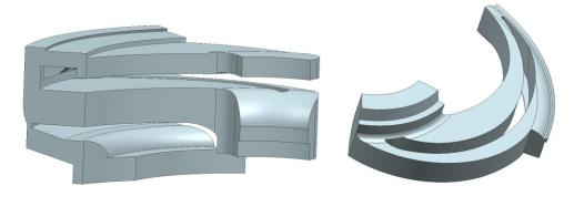
Computational domain includes impeller blade channel (Fig. 1a) and diffuser channel (Fig. 1b).
a |
b |
|
Fig. 1. Computational domain of pump stage: a – impeller, b – diffuser
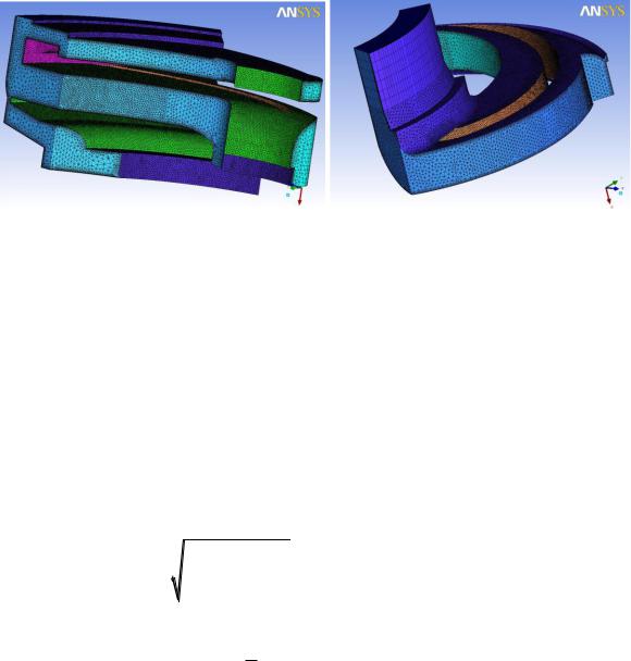
ANSYS ICEM CFD program was used to construct volumetric grid of a computational domain (Fig. 2a, 2b). Elements of the grid are tetrahedral; they are large in the flow core and dense in a near-wall region. Prismatic layer was created to describe a boundary layer which is adjacent to the impeller and diffuser solid walls. A total number of mesh elements amounts to ~ 2,3 mln (impeller ~ 1,4 mln, diffuser ~ 0,85 mln).
17
a |
b |
Fig. 2. Volumetric grid of a computational domain: a – impeller, b – diffuser
ANSYS CFX gas-hydrodynamic package was used for numerical calculating. Mass flow rate Q was selected as an input boundary condition and total pressure P – as an output boundary condition. Flow state was turbulent. The standard k–ε turbulence model was used to close the Reynolds equations. Water was selected as a working fluid. Rotation frequency of the impeller was set. Both periodicity and fluid sticking to the walls conditions were indicated.
Solver parameters were set as follows:
– Convergence criterion: convergence is controlled by the discrepancy of
|
|
|
|
|
|
velocity components: |
u |
u |
2 |
||
i |
i 1 |
|
10 4 , where ui – velocity components on |
||
|
n |
|
n |
|
|
i iteration, n - a number of elements.
– Time step [3]: t 0,3 uh , where h – a minimum size of an element, u –
an average flow rate. Representative calculating time: t 3 10 4 s.
Such stage characteristics as head and efficiency are calculated by means
of the following equations [4,5]: |
|
|
|
|
– head: H |
Ptot _ in Ptot _ out |
, |
where Ptot_in – total pressure at impeller inlet; |
|
|
||||
|
g |
|
|
|
Ptot_out – total pressure at diffuser outlet; ρ – fluid density. |
||||
– hydraulic |
efficiency: |
Г |
g Q H , where ρ – fluid density, Q – |
|
|
|
M |
||
|
|
|
|
|
fluid supply, H – head, ω = 2πf – cyclic frequency, M – torque.
18
Results
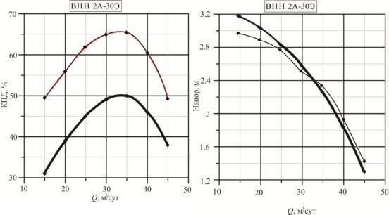
Pump stage characteristics were constructed on the basis of the above calculations. Calculated data were compared with the bench testing results (Fig. 3).
Fig. 3. Comparison of numerical calculation and experiment
for stage ВНН 2А-30Э: thick line – numerical calculation, thin line – experiment
Depending on the pump fluid supply the head relative error is in the range of 3–8 %. The efficiency error is more than 10 %. However, in flow calculating there were obtained only hydraulic efficiency values; those of mechanical and volumetric efficiency were not taken into account.
The technique under consideration was tested for stages of different types, sizes and nominal fluid supply. Numerical calculating and bench testing techniques have a small head discrepancy for pump optimal operating modes (the relative error does not exceed 7 %). Therefore, this technique can be recommended for calculating characteristics of submersible pump stages.
Head value discrepancy between numerical calculating and experimental techniques increases at suboptimal operating modes. This can be explained by the growth of leakage value (leakage in the gap between the impeller and diffuser).
Conclusions
The following conclusions can be drawn from the research:
–Numerical calculating technique for submersible pump stages has been developed;
–The technique was tested for the stages of different types, sizes and nominal fluid supply;
19
– The relative error of head values at pump optimal operating modes does not exceed 7 %. The technique can be recommended for calculating head-flow characteristics of submersible pump stages.
References
1.Свобода Д.Г., Жарковский А.А. Экспериментальные и расчётные
исследования осевого насоса с быстроходностью ns = 570 // Известия Самар. науч. центра РАН. – 2013. – Т. 15, № 4 (2). – С. 579–582.
2.Алексенский В.А., Жарковский А.А., Першаков Н.Г. Модернизация консольно-моноблочных центробежных насосов с использованием методов CFD // Известия Самар. науч. центра РАН. – 2012. – Т. 1, № 1. – С. 328–331.
3.Белов И.А., Исаев С.А. Моделирование турбулентных течений: учеб. пособие. – СПб.: Изд-во Балт. гос. техн. ун-та, 2001. – 108 с.
4.Богданов А.А. Погружные центробежные электронасосы для добычи нефти (расчёт и конструкция). – М.: Недра, 1968. – С. 272.
5.Ломакин А.А. Центробежные и осевые насосы. – 2-е изд., перераб.
идоп. – М. – Л.: Машиностроение, 1966. – 364 с.
20