

ppl_06_e2
.pdfID: 3658
Customer: Oleg Ostapenko E-mail: ostapenko2002@yahoo.com
Customer: Oleg Ostapenko E-mail: ostapenko2002@yahoo.com
CH AP T ER 1 0 : ENG INE H AND
it stops detonation by cooling the charge temperature. So the mixture control can be left at fully rich in the climb.
U s e o f t h e Mi x t u r e Co n t r o l a t Al t i t u d e . |
||||
During the cruise phase of flight, the mixture can be leaned off to give better fuel |
When leaning |
|||
economy. If your aircraft has an exhaust gas temperature (EGT) gauge, this can |
||||
the fuel/ |
|
|
||
be used to give an indication of the correct mixture setting. If the mixture control is |
|
|
||
air mixture |
||||
moved towards lean, the EGT will peak when the air-fuel ratio is 15:1. |
at altitude, |
|||
It should be remembered, though, that this ratio should not be used, as detonation |
to obtain the most efficient |
|||
mixture setting, the control is |
||||
can occur. On reaching the peak EGT, the mixture control should be moved towards |
first moved towards the LEAN |
|||
rich. The cylinder head temperature should then reduce. The aircraft’s flight manual |
position until the engine RPM |
|||
will specify a temperature drop which will give the rich cruise setting. |
decreases then the mixture |
|||
control is moved slightly to the |
||||
|
||||
If an EGT gauge is not fitted, the following alternative method of setting the correct |
RICH side of peak RPM. |
|
|
mixture strength for the cruise, by using the engine RPM as a guide, may be |
|
utilised. |
|
Moving the mixture control from the fully rich position to a weaker setting brings the |
|
air-fuel ratio closer to the chemically correct value of approximately 15:1 . Remember, |
|
at this ratio all of the air and fuel are consumed and the heat released by combustion |
|
is at its maximum. More heat means more power, so with a fixed pitch propeller the |
|
RPM will rise. But continuing to weaken the mixture from this point will cause the |
|
RPM to reduce. |
|
Move the mixture control to a position a little richer than the chemically correct |
|
position, and note that the RPM decreases slightly. This setting can be assumed to |
|
be the optimum for economical cruising flight. |
|
Id l e Cu t - O f f .
The normal method of shutting down an aircraft engine is by cutting off the fuel supply. This has several advantages over the method used in automobile engines where the ignition is switched off.
Cutting off the fuel ensures that the engine cannot ‘run on’, a phenomenon which can occur if the engine has any incandescent carbon deposits in the combustion chamber. It also means that no fuel is allowed to be sucked into the cylinders during those few last revolutions before the engine stops. Any fuel brought into the cylinder after combustion ceases will tend to wash the lubricating oil from the cylinder walls, and, as a consequence, the next time it starts, the engine suffers wear.
In the chapter on carburation, the idle cut-off section of the carburettor was described in some detail.
The idle cut-off may be a separate control, or it may be incorporated in the mixture control lever. By closing the throttle and pulling the mixture control lever to the idle cut-off position, the fuel flow between the float chamber and the venturi is cut off.
The normal
method of shutting down
an aircraft
engine is to close the throttle and move the mixture lever to the idle cut-off position.
153

Order: 6026
Customer: Oleg Ostapenko E-mail: ostapenko2002@yahoo.com
Customer: Oleg Ostapenko E-mail: ostapenko2002@yahoo.com
CH AP T ER 1 0 : ENG INE H ANDLING Q U EST IO NS
R |
e p r e s e n t a t i v e P P L - |
t y p e q u e s t i o n s |
k n o w l e d g e o f En g i n e H |
a n d l i n g . |
|
1.To correctly set the fuel/air mixture whilst in flight, the control is moved to the lean position until engine RPM:
a.Drops and then the mixture control is then moved slightly to the RICH side of peak RPM
b.Rises and then the mixture control is left in that position
c.Decreases by approximately 150 RPM. The mixture control is then moved slightly more towards the LEAN position
d.Decreases. The mixture control is then left in that position
2.What is an appropriate action to take if you have a carburettor fire on startup?
a.Deselect carburettor heat
b.Select mixture control to Idle Cut-Off
c.Turn the starter switch to “Off”
d.All of the above
3Immediately after starting an aircraft engine, you must check the starter warning light. If it is still illuminated you should:
a.Monitor it for 30 seconds. If it remains illuminated shut down the engine
b.Do nothing. The starter warning light is designed to stay on while the engine is running
c.Shut down the engine immediately
d.Shut down the engine, count to 30, then attempt a re-start
4.After starting a cold aircraft engine the oil pressure gauge should register:
a.Immediately; otherwise shut down the engine
b.Within 30 seconds; otherwise shut down the engine
c.By the time pre-flight checks are complete; otherwise shut down the engine
d.Immediately, otherwise, as long as the oil levels were at an adequate level before start-up, and RPM is within limits, it is probable that the oil pressure gauge is faulty and this should be reported after the flight
5.The normal method for shutting down an aircraft engine is to:
a.Switch the starter switch to off
b.Move the mixture to idle cut-off (ICO)
c.Close the throttle
d.Close the throttle and move the mixture to ICO
154

ID: 3658
Customer: Oleg Ostapenko E-mail: ostapenko2002@yahoo.com
Customer: Oleg Ostapenko E-mail: ostapenko2002@yahoo.com
CH AP T ER 1 0 : ENG INE H ANDLING Q U
6.On take-off, the throttle should be operated:
a.Smoothly, to avoid a weak cut, allowing the engine to respond as fast as it is able, and permitting the mixture-strength and charge quantity to change in line with the engine requirements
b.Smoothly, but it may be opened abruptly if several aircraft are waiting to take off
c.Smoothly, following a count of three
d.As required by the air traffic situation
Question |
1 |
2 |
3 |
4 |
5 |
6 |
Answer |
|
|
|
|
|
|
T h e a n s w e r s t o t h e s e q u e s t i o n s c a n b e f o u n d a t
155
Customer: Oleg Ostapenko E-mail: ostapenko2002@yahoo.com
156
Customer: Oleg Ostapenko E-mail: ostapenko2002@yahoo.com
CHAPTER 11
ELECTRICAL SYSTEMS
157

Order: 6026
Customer: Oleg Ostapenko E-mail: ostapenko2002@yahoo.com
Customer: Oleg Ostapenko E-mail: ostapenko2002@yahoo.com
CH AP T ER 1 1 : ELECT R ICAL SY ST EMS
158

ID: 3658
Customer: Oleg Ostapenko E-mail: ostapenko2002@yahoo.com
Customer: Oleg Ostapenko E-mail: ostapenko2002@yahoo.com
CH AP T ER 1 1 : ELECT R ICAL SY S
INTRODUCTION.
The electrical system in a light aircraft operates components and services such as the landing light, radios, turn co-ordinator, starter motor, transponder, navigation equipment, pitot heater, electric fuel pump and so on.
ELECTRICAL CURRENT.
Di r e c t Cu r r e n t .
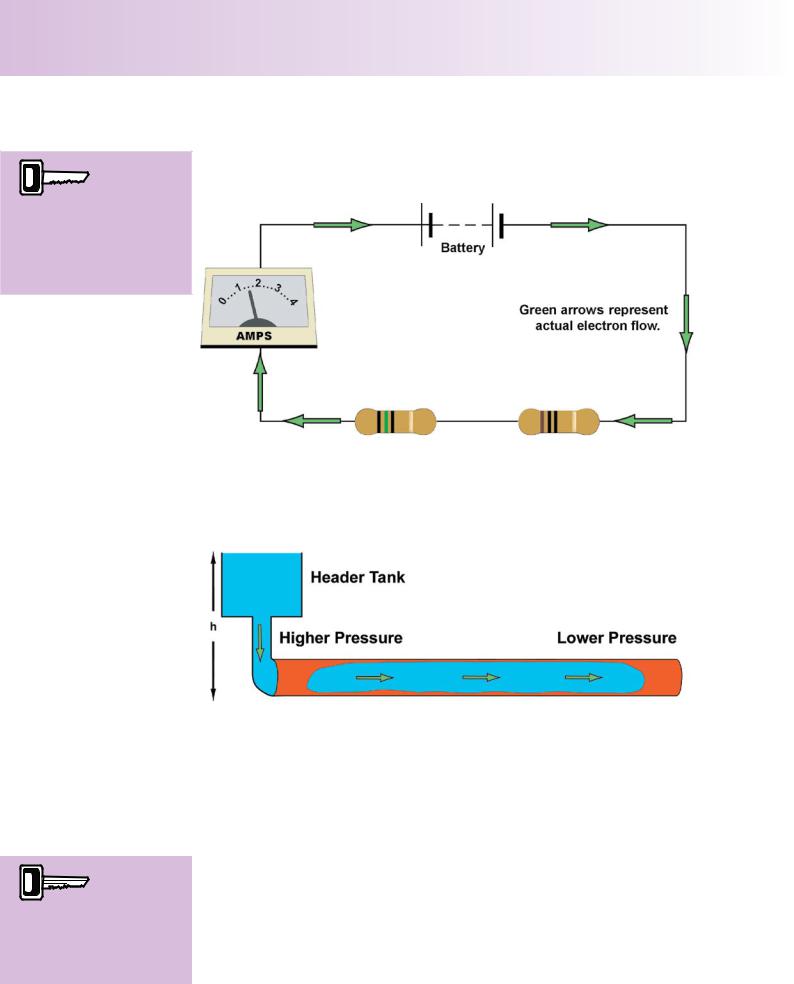
Most light aircraft use a direct current (DC) supply to drive the electrical services.
Figure 11.1 Direct Current - Actual Electron Flow.
The term direct current implies that the electrons which make up the flow of current are travelling in one direction only. Convention, used by electricians and electrical engineers, states that the electrons flow from a positive terminal to a negative terminal, but the scientific explanation of electric current shows that actual electron flow is from the negative pole to the positive pole as depicted in Figure 11.1. The difference between the directions of “conventional flow” and “actual flow” will not concern you for your PPL studies.
Al t e r n a t i n g Cu r r e n t .
In an alternating current (AC) the electrons in the circuit oscillate backwards and forwards about a mean point. This might seem at first glance as if it would be rather ineffective, one movement cancelling out the other, but this is not the case. Any movement of electrons generates electrical energy.
Figure 11.2. Electrons Move Backwards and Forwards in an Alternating Current Circuit.
Although alternating current is used in light aircraft only for power generation, it is used much more than direct current in commercial airliners where relatively light, powerful, reliable and efficient machinery is required.
159
Order: 6026
Customer: Oleg Ostapenko E-mail: ostapenko2002@yahoo.com
Customer: Oleg Ostapenko E-mail: ostapenko2002@yahoo.com
CH AP T ER 1 1 : ELECT R ICAL SY ST EMS
The strength of  current flowing through a conductor, such
as an aircraft electrical cable, is measured in Amperes, commonly known as Amps, by an instrument called an Ammeter.
Cu r r e n t F l o w .
The strength of current flowing through a conductor, such as an aircraft electrical cable, is measured in Amperes, commonly known as Amps, by an instrument called an Ammeter.
Figure 11.3 An Ammeter Measuring Current Flow.
W a t e r An a l o g y .
Imagine the current flowing through a cable as being similar to water flowing in a pipeline.
The pressure required to
cause current to flow along
a conductor is termed the voltage or electromotive force, which is measured in volts on a voltmeter.
Figure 11.4 The Water Analogy of the electric current flow.
This analogy, pictured in Figure 11.4, is called the ‘water analogy’. For people not too well acquainted with electricity, the water analogy can come in very handy in almost all situations when dealing with simple direct current circuits.
For water to flow through the pipe, a pressure difference must exist across the pipe. The pressure at one end of the pipe must be greater than the pressure at the other end. Pressure difference is usually obtained by placing a header tank above the level of the whole water system and thus the force of gravity causes the water to flow.
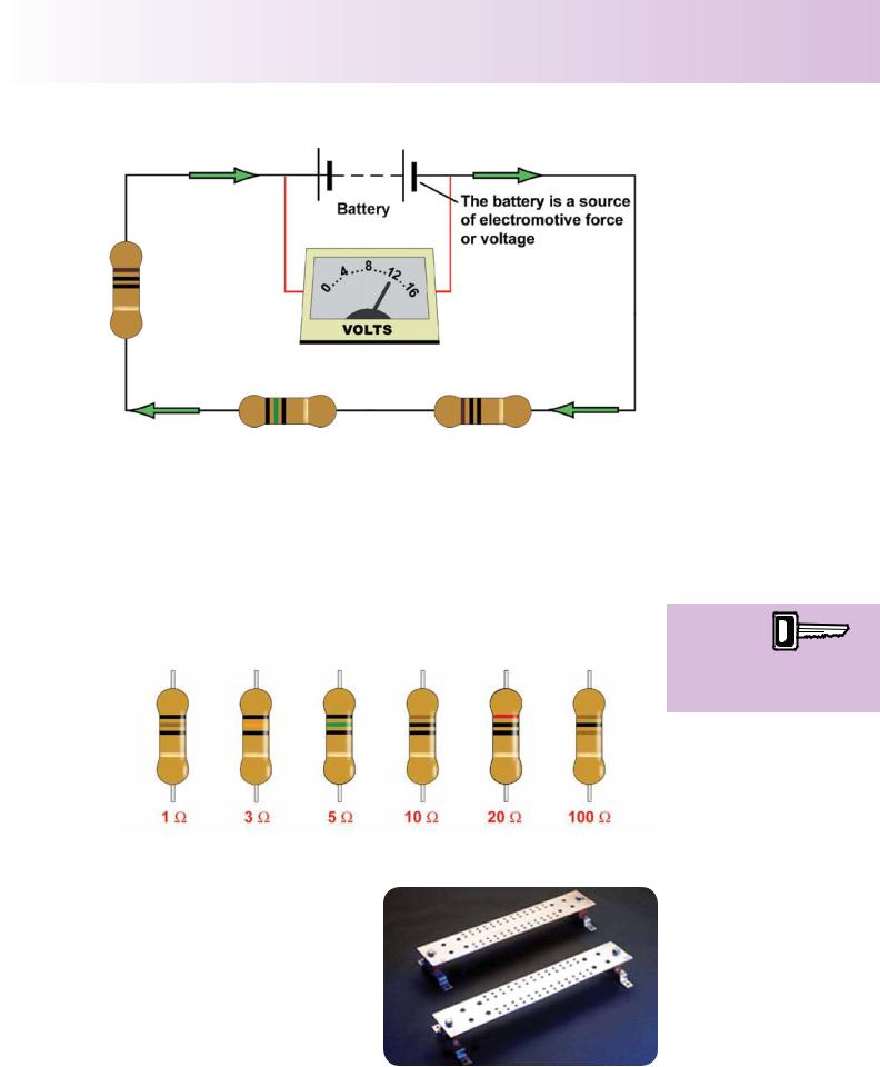
V o l t a g e .
In an electrical circuit, the “pressure difference” required to move electrons along a wire is termed the “electromotive force” (EMF), or simply “voltage”, which is measured in volts on an instrument called a voltmeter.
160
ID: 3658
Customer: Oleg Ostapenko E-mail: ostapenko2002@yahoo.com
Customer: Oleg Ostapenko E-mail: ostapenko2002@yahoo.com
CH AP T ER 1 1 : ELECT R ICAL SY S
Figure 11.5 A Voltmeter Measuring Voltage, or Electromotive Force.
This electromotive force, or voltage, can be generated in several ways. In a light aircraft, the main source of EMF or voltage is the generator or alternator, with the battery serving as a back-up. The battery can run the aircraft’s essential services for about 30 minutes, if an aircraft’s generator or alternator fails. The battery also supplies power for engine starting.
R e s i s t a n c e a n d R e s i s t o r s .
Any component or characteristic of a circuit which opposes electron flow is called a resistor. Components which are designed specifically to provide resistance are called resistors. Resistors are used in the construction of all practical circuits.
Any
component or characteristic
of a circuit
which opposes electron flow is called a resistor.
Figure 11.6 A range of resistors of differing values. Resistance is measured in Ohms (W).
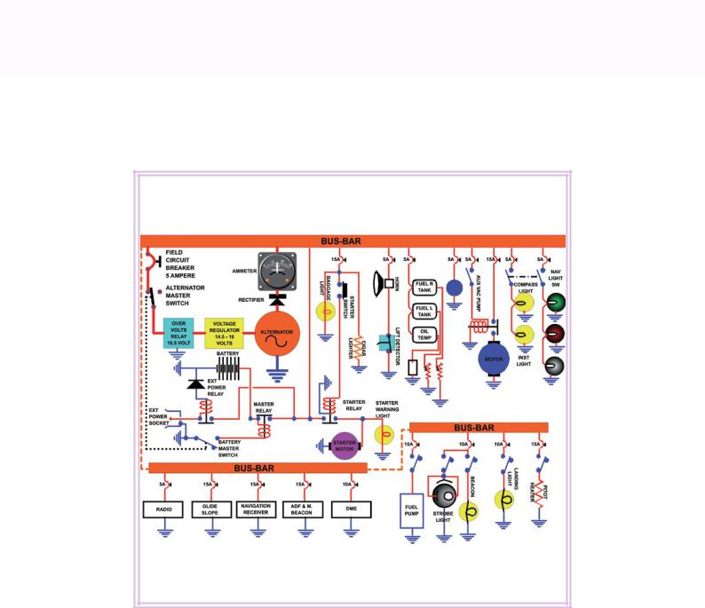
POWER DISTRIBUTION. |
|
|
Electric current is fed by a generator |
|
|
or alternator to the individual electrical |
|
|
components of any aircraft electrical |
|
|
system via busbars, which are merely |
|
|
convenient collection and distribution |
|
|
points for current flow. |
|
|
The busbars are usually solid copper |
|
|
bars which are drilled and tapped so |
Figure 11.7 Busbars. |
|
that supply and distribution cables can |
||
|
||
be attached to them. |
|
161
Order: 6026
Customer: Oleg Ostapenko E-mail: ostapenko2002@yahoo.com
Customer: Oleg Ostapenko E-mail: ostapenko2002@yahoo.com
CH AP T ER 1 1 : ELECT R ICAL SY ST EMS
Si n g l e - P o l e .
Most light aircraft which utilise metal construction are single-pole or earth-return electrical systems. This means that the individual components are supplied via the busbars and cables, and to complete the circuit, the return current flows back through the metal of the airframe.
A double-pole electrical
system requires one
cable to take the current to the component and a second cable to complete the circuit.
Do u b l e - P o l e .
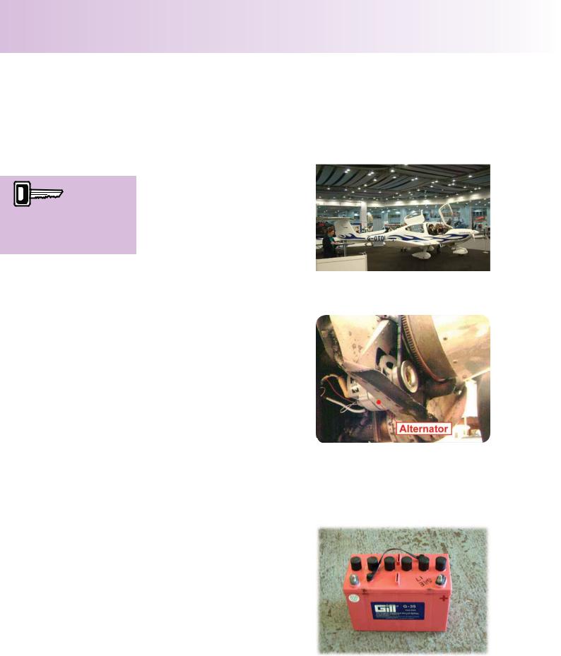
Aircraft which are made of nonconductive materials, like the Diamond Star shown in Figure 11.8, require a double-pole or two wire system. This means that as well as having a cable taking the current flow to each individual component, another cable is required to complete the electrical circuit back to the negative side of the generator or alternator.
Figure 11.8 The Airframe of this Diamond Star is made of non-conductive materials.
Al t e r n a t o r s a n d G e n e r a t o r s .
Alternators and generators produce the electricity needed to charge the battery and to operate the aircraft’s electrical equipment. Put simply, while a generator produces direct current, an alternator produces alternating current internally, and uses a device called a diode rectifier to turn the alternating current into direct current, which is then fed to the aircraft circuit.
Alternators are commonly used in |
|
aircraft because of their dependability. |
Figure 11.9 An Alternator. |
While a generator will generally require
the engine to run at approximately half speed before it will deliver its full output, an alternator will give almost full power even at engine idling speed.
BATTERIES.
In a light aircraft, a lead-acid battery provides a store of electrical energy enabling the engine to be started. The battery is also a source of emergency electrical power, in the event of alternator or generator failure.
A battery is made up of a number of cells connected in series which convert chemical energy into electrical energy
Figure 11.10a An aeroplane battery.
162