

нормальная рентгенанатомия легких
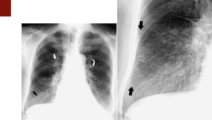
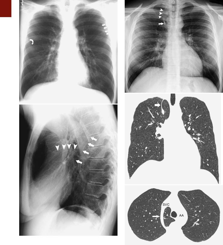
.pdf■ FIGURE 1-15 Enlarged hilar lymph nodes on a lateral projection. A magnified view of a lateral chest radiograph in a patient with sarcoidosis shows a lobulated contour and increased opacity in the hila (arrows), characteristic of hilar lymph node enlargement.
and anterior regions of the right middle lobe, lingula, and lower lobe.25 In these areas they measure approximately 0.1 mm in thickness and can be identified on visual inspection of the pleural or cut surfaces of the lung.
The normal secondary lobule cannot be identified on a chest radiograph. Only when the interlobular septa are rendered visible as septal lines as a result of thickening by fluid or tissue (such as edema or carcinoma) can the lung between two lines be recognized as a secondary lobule.22 Septal lines (Kerley’s lines) are identified most commonly in the anterior and lateral aspects of the lungs, where they are best developed (Fig. 1-16).
Acinus
The pulmonary acinus is the portion of lung distal to the terminal bronchiole and is composed of respiratory bronchioles, alveolar ducts, alveolar sacs, alveoli and their accompanying vessels, and connective tissue.26 Acinar diameter ranges between 6 and 10 mm.27,28
Segments and Lobes
The normal anatomy of the pulmonary segments is variable, complex, and difficult to appreciate on radiographs (Fig. 1-17). It can, however, be readily assessed on CT (see Chapter 2). An approximate location of an abnormality
C H A P T E R 1 ● Normal Chest Radiograph |
13 |
within a given segment can often be determined by careful analysis of its location on frontal and lateral radiographs.
There are two widely accepted nomenclatures for bronchopulmonary anatomy: the Jackson-Huber and Boyden classifications. The Jackson-Huber nomenclature is the most widely adopted terminology in North America and the one used throughout this book.29,30 The Boyden classification uses a numerical system for identifying the bronchial segments. The segmental bronchi are identified by the letter “B” followed by a number, and the segments that they supply are identified by the letter “S” followed by the corresponding number (see Chapter 2, Fig. 2-19).
The right upper lobe usually has three segments: apical (S1 in the Boyden classification), anterior (S3), and posterior (S2). The middle lobe has two segments: lateral (S4) and medial (S5). The right lower lobe has five segments: superior (S6), medial basal (S7), anterior basal (S8), lateral basal (S9), and posterior basal (S10) (Fig. 1-17).
The left upper lobe usually has two segments: apicoposterior (S1 and S2) and anterior (S3). The lingula has two segments—superior (S4) and inferior (S5)—and the left lower lobe has four—superior (S6), anteromedial basal (S7 and S8), lateral basal (S9), and posterior basal (S10).
The apical segment has the shape of a truncated cone, extends to the apex of the lung, and does not abut the minor fissure. The anterior segment of the upper lobe occupies the ventral portion of the upper lobe and abuts the minor fissure, whereas the posterior segment occupies the dorsal portion and abuts the major fissure. The lateral and medial segments of the middle lobe abut the minor fissure and extend caudally to the level of the diaphragm. The lateral segment abuts the lateral chest wall and the medial segment abuts the heart. The superior segment of the right lower lobe has the shape of a truncated cone; it forms the apex of the lower lobe and is situated behind the major fissure below the level of the posterior segment of the upper lobe. The medial basal segment is situated immediately inferior and medial to the right hilum above the level of the inferior pulmonary vein. It is generally the smallest pulmonary segment. The location of the remaining basal segments is best remembered with the mnemonic ALP. On a lateral radiograph the anterior segment is the most anterior basal segment and abuts the posterior aspect of the major fissure, the posterior basal segment occupies most of the posterior costophrenic gutter, and the lateral basal segment lies between these two segments. On a frontal radiograph, the anterior segment is the most lateral of these segments and the posterior basal segment the most medial.
The two segments of the left upper lobe and the four segments of the left lower lobe have an anatomic distribution that is similar to the corresponding segments in the right lung. The lingular segments are stacked one on top of the other, thus the designation superior and inferior lingular segments rather than side by side as in the right middle lobe.
Radiographic Density
The radiopacity of the lungs is a result of the absorptive power of each of its components: gas, blood, and tissue.
14 P A R T O N E ● Normal Chest
A B
■ FIGURE 1-16 Thickening of the interlobular septa in interstitial pulmonary edema. A, A frontal chest radiograph in a patient with left heart failure and interstitial pulmonary edema shows septal (Kerley’s B) lines (black arrow). Also noted is bronchial cuffing as a result of edema (straight arrow) and increased size of the anterior segmental left upper lobe pulmonary artery (curved arrow), which has a greater diameter than the adjacent bronchus does. Also noted are small bilateral pleural effusions. B, A magnified view of the right lower lung region better demonstrates the septal lines
(arrows).
The density of bloodless collapsed lung tissue is 1.065 g/ mL31; the density of blood is 1.052 g/mL.32 Nonaerated lung in vivo consists of approximately half blood and half tissue,33 so the mean density of collapsed lung containing blood is approximately 1.06 g/mL.34 By comparison, water has a density of 1.0 g/mL, and air has a density of 0. By using the average figures for total maximal tissue volume derived from anatomic and physiologic measurements and the predicted total lung capacity of a 20-year-old man who is 170 cm tall (6500 mL), the estimated average density of lung tissue is 740 g 7198 mL = 0.103 g/mL.22 A considerable portion of lung tissue—logically, the air-contain- ing parenchyma—must possess a density less than this value to compensate for the relatively high density of the visible blood vessels.
On a properly positioned radiograph the radiographic density of the right and left lungs is symmetric (Fig. 1-18). If the patient is rotated, the lung closer to the film is more uniformly radiopaque (whiter) than the other lung; conversely, the lung that is farthest away from the film is uniformly less radiopaque (more black) (Fig. 1-18).22 In one investigation using phantoms, approximately 80% of this unilateral increase in radiographic density was found to be the result of asymmetric absorption of the primary x- ray beam, with the remaining 20% being due to scatter radiation.35 Measurement of chest wall thickness showed
that the x-ray beam traversed less tissue on the side of increased film blackening (or, conversely, more tissue on the side of increased opacity), chiefly as a result of the pectoral muscles.
Provided that the patient is not rotated and the x-ray beam is centered properly, any discrepancy in the density of the two lungs must be interpreted as being abnormal.
The cause varies from such benign conditions as scoliosis and congenital absence of the pectoral muscles to more significant disorders such as Swyer-James-McLeod syndrome.
Pulmonary Markings
Correct interpretation of the chest radiograph requires a thorough knowledge of the pattern of linear markings throughout the normal lung (see Fig. 1-1). These markings are created by the pulmonary arteries, bronchi, veins, and accompanying interstitial tissue. The pulmonary arteries fan outward from both hila and gradually taper as they proceed distally (Fig. 1-19). In the normal state, they are visible up to about 1 to 2 cm from the visceral pleural surface over the convexity of the lung, at which point it is composed predominantly of acini.
The posteroanterior chest radiograph of a normal erect individual invariably shows some discrepancy in the size
C H A P T E R 1 ● Normal Chest Radiograph |
15 |
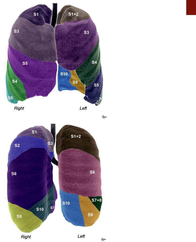
■ FIGURE 1-17 A, Pulmonary lobes and segments: anterior view. A schematic drawing superimposed on a three-dimensional surface reformatted image obtained with a multidetector CT scanner shows the location of the pulmonary segments and lobes on the anterior surface of the right and left lungs. The segments that form the anterior surface of the right lung include the apical (S1) and anterior (S3) segments of the right upper lobe, the lateral (S4) and medial (S5) segments
of the right middle lobe, and the anterior basal (S8) segment of the right lower lobe. The anterior view of the left lung shows the location of the apicoposterior segment (S1+2), anterior (S3) segments, and superior
(S4) and inferior (S5) lingular segments of left the upper lobe, as well as the anteromedial basal (S7+8) segment. Because the heart was removed from the original image, the lateral basal (S9) and posterior basal (S10) segments of the left lower lobe are also demonstrated on this reformatted image. B, Pulmonary lobes and segments: posterior view. The segments that form the posterior surface of the right lung include the apical (S1), posterior (S2), and anterior (S3) segments of the right upper lobe and the superior (S6), lateral basal (S9), posterior basal (S10), and (adjacent to the heart, which is not shown) medial (S7) basal segments of the right lower lobe. The segments that form the posterior surface of the left lung include the apicoposterior (S1+2) segments of the left upper lobe and the superior (S6), anteromedial basal (S7+8), lateral basal (S9), and posterior basal (S10) segments of the left lower lobe.
A
B
16 P A R T O N E ● Normal Chest
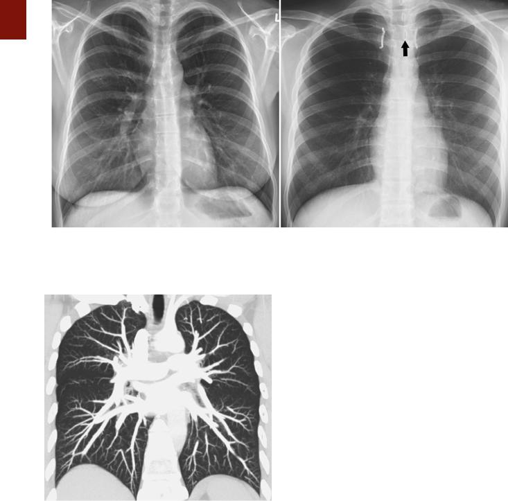
A B
■ FIGURE 1-18 Radiographic density on well-centered and slightly oblique chest radiographs. A, Properly centered radiograph showing a symmetric radiographic density in the right and left lungs. B, Frontal radiograph showing that the medial ends of the clavicles (highlighted in white) are not equidistant from the spinous process (arrow), thus indicating that the patient is slightly rotated. This results in an asymmetric radiographic density, with the lung closer to the film more uniformly radiopaque (whiter) than the other lung.
■ FIGURE 1-19 Normal pulmonary vasculature. A maximum intensity projection image obtained from a CT scan shows the pulmonary arteries fanning outward from both hila and gradually tapering as they proceed distally and the pulmonary veins coursing toward the left atrium. Normally, the pulmonary arteries are visible up to about 1 to 2 cm from the visceral pleural surface.
of the pulmonary vessels in the upper lung zones as compared with the lower zones as a result of pressure-related differences in blood flow from the apex to the base (a unit volume of lung at the base of the thorax has four to eight times the blood flow of a similar volume at the apex) (see Fig. 1-1).22 In a recumbent individual, a decrease in the
influence of gravity renders this discrepancy in vascular size minimal (Fig. 1-19).
Pleura
The pleural space is enclosed by the visceral pleura, which covers the lungs, and by the parietal pleura, which lines the chest wall, diaphragm, and mediastinum. The two join at the hila. The visceral pleura consists of mesothelial cells overlying two layers of elastic tissue that separate a small amount of connective tissue and lymphatic vessels. Because the combined thickness of the normal parietal and visceral pleural layers is approximately 0.2 mm, the pleura over the convexity of the lungs and over the diaphragmatic and mediastinal surfaces is not visible on the chest radiograph. Each pleural space normally contains 8.4 ± 4.3 mL of fluid, which corresponds to a total of 0.26 mL/kg of pleural fluid.36 Fluid is usually produced in the parietal pleura and drained at the visceral pleura. Fluid tends to be drawn into the space because recoil of the lung and chest wall acts as an opposing force over most of the range of respiratory volumes. The pressure acting on the pleural surface (pleural pressure, Ppl) at midlung height averages approximately −6 cm H2O during a tidal breath, becomes more negative with deeper breaths, and is more negative at the top of the space than at the bottom (decreasing by 0.2 cm H2O/cm height).37 Control of the volume and composition of pleural liquid is affected by a number of mechanisms, including Starling’s forces (providing filtration through the parietal and absorption through the visceral mesothelium), lymphatic drainage, and the activity of mesothelial cells.37
Interlobar Fissures
Fissures are invaginations of the pleura that extend from the outer surface of the lung into its substance. They are traditionally considered in two groups: those that separate the lungs into the three right-sided and two left-sided lobes (normal fissures) and those that occur within one of the lobes themselves (accessory fissures). The normal fissures are the minor fissure (located between the right middle and upper lobes), the right major fissure (between the combined right upper and middle lobes and the right lower lobe), and the left major fissure (between the left upper and lower lobes) (Fig. 1-20).
The normal major fissures are seldom seen on a posteroanterior radiograph. Occasionally, the upper edge may be visible when extrapleural fat extends into the major fissure and abuts the posterior chest wall. This results in a curved line or stripe that extends downward and laterally from a few centimeters above the level of the hilum. On a lateral chest radiograph, the major fissures
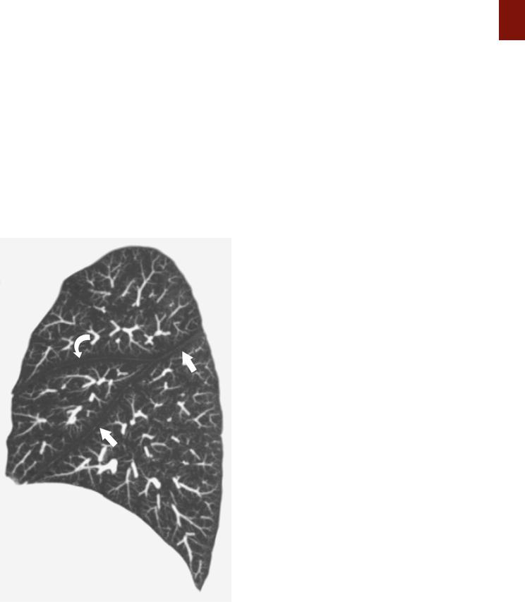
■ FIGURE 1-20 Normal right interlobar fissures. A sagittal maximum intensity projection image obtained from a CT scan shows normal position of the right major (straight arrows) and minor (curved arrow) interlobar fissures.
C H A P T E R 1 ● Normal Chest Radiograph |
17 |
can be seen as lines that extend obliquely downward and forward from the level of the fifth thoracic vertebra and end at the diaphragm a few centimeters behind the anterior pleural gutter (Fig. 1-21). The top of the left lower lobe is usually higher than the top of the right.
The minor fissure separates the anterior segment of the right upper lobe from the middle lobe and lies in a roughly horizontal plane lateral to the right hilum. The fissure has a slight curvature, the anterior aspect generally being lower than the posterior and the lateral aspect lower than the medial (Fig. 1-21). Some of the minor fissure is seen on chest radiography in approximately 50% to 80% of patients.22,38 It typically ends lateral to the interlobar pulmonary artery.
In the majority of cases the interlobar fissures are incomplete. In a study of 100 fixed and inflated lung specimens (50 right and 50 left), an incomplete fissure (lobar fusion) was found between the right lower and upper lobes in 70% of cases and between the right lower and middle lobes in 47%.39 In the left lung, fusion between the lower and upper lobes was less frequent than on the right: 40% of cases showed an incomplete fissure between the left lower lobe and the superior part of the upper lobe, and 46% showed an incomplete fissure between the lower lobe and lingula. Incompleteness of the minor fissure was far more common than incompleteness of any portion of either major fissure: of the 50 right lungs examined, extensive fusion was present in 88%, especially medially; fusion was more common and usually more extensive between the middle and upper lobes (across the minor fissure) than between the middle and lower lobes (across the major fissure).39
Accessory Fissures
Any portion of lung may be separated partly or completely from adjacent pulmonary tissue by an accessory fissure. The anatomic incidence of such fissures is much higher than generally appreciated, about 50%.22 However, they are visible on only about 10% to 15% of chest radiographs.38 These fissures vary in their degree of development from superficial slits not more than 1 cm deep to complete fissures that extend all the way to the hilum. The most common are the azygos, inferior, and superior accessory
fissures and the left minor fissure.
Azygos Fissure
The azygos fissure is created by downward invagination of the azygos vein through the apical portion of the right upper lobe.40 It is manifested radiographically as a curvilinear shadow that extends obliquely across the upper portion of the right lung and terminates at a variable distance above the right hilum in a teardrop shadow caused by the azygos vein itself (Fig. 1-22). Because the vein runs outside the parietal pleura, four pleural layers (two parietal and two visceral) form the fissure. The fissure is visible on about 0.5% of chest radiographs.
Inferior Accessory Fissure
The inferior accessory fissure separates the medial basal segment from the remainder of the lower lobe. It is seen
18 P A R T O N E ● Normal Chest
A
A
B
B
■ FIGURE 1-21 Normal major and minor fissures. A, Frontal chest radiograph showing the right minor fissure (curved arrow). The major fissures are seldom seen on a posteroanterior radiograph. In this patient the upper edge of the left major fissures is seen as a curved stripe (straight arrows) that extends downward and laterally from a few centimeters above the level of the left hilum. B, Lateral radiograph showing the right major (straight arrows) and minor (arrowheads) fissures. The left major fissure normally projects slightly posterior to the right major fissure and is not well seen on this radiograph.
C
■ FIGURE 1-22 Azygos fissure. A, Posteroanterior chest radiograph showing the azygos fissure as a curvilinear line (arrowheads) extending obliquely across the upper portion of the right lung. Note the azygos vein (arrow) coursing within the fissure. B, Coronal reformatted image from a CT scan showing the azygos fissure (arrow). C, Cross-sectional CT scan showing the azygos arch (arrow) as it extends anteriorly from the paravertebral region to drain into the superior vena cava (SVC). AA, aortic arch.
on 5% to 13% of chest radiographs, most commonly on the right, as a thin line extending from the medial aspect of the hemidiaphragm (most commonly right) obliquely cephalad and medially toward the right hilum (Fig. 1-23).38,41
A
B
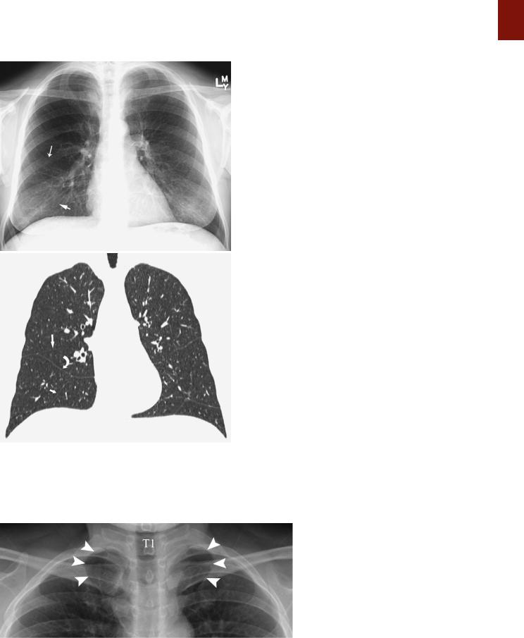
■ FIGURE 1-23 Accessory fissures. A, Posteroanterior chest radiograph showing the right minor fissure (long arrow) and right inferior accessory fissure (short arrow). B, Coronal reformatted image from a multidetector CT scan showing the right minor fissure (long straight arrow), right inferior accessory fissure (short straight arrow), and right superior accessory fissure (curved arrow). Also noted are several accessory fissures in the left lung.
C H A P T E R 1 ● Normal Chest Radiograph |
19 |
Superior Accessory Fissure
The superior accessory fissure separates the superior segment from the basal segments of the lower lobes, more commonly on the right. The fissure can be identified on approximately 3% of lateral chest radiographs.38
Left Minor Fissure
The left minor fissure is present in 8% to 18% of individuals but is seen on radiographs in only 1.6% of cases. The left minor fissure tends to be in a slightly more cephalad location than the right minor fissure and, like the right minor fissure, tends to be dome shaped (convex superiorly).42,43
Pulmonary Ligament
The pulmonary ligament consists of a double layer of pleura that tethers the medial aspect of the lower lobe to the adjacent mediastinum and diaphragm.44 It is formed by the mediastinal parietal pleura as it reflects over the main bronchi and pulmonary arteries and veins onto the surface of the lung as the visceral pleura. Although the pulmonary ligament is anatomically extraparenchymal, it is contiguous laterally with a cleavage plane in the parenchyma of the lower lobe known as the intersegmental (intersublobar) septum, which separates the medial from the posterior basal segments. The left pulmonary ligament is closely related to the esophagus and is bordered posteriorly by the descending aorta; the shorter right ligament can be situated anywhere along an arc that extends from the inferior vena cava anteriorly to the azygos vein posteriorly.
The pulmonary ligament is not seen on posteroanterior or lateral chest radiographs. It determines the shape of the collapsed lower lobe in patients with atelectasis and the shape of the collapsed lung in patients with pneumothorax.
Thoracic Inlet
The thoracic inlet represents the junction between structures at the base of the neck and those of the thorax. It parallels the first rib and is higher posteriorly than anteriorly (Fig. 1-24). Therefore, on a frontal chest radiograph, an opacity that is effaced on its superior aspect and that projects at or below the level of the clavicles must be situated anteriorly, whereas one that projects above the clavicles is retrotracheal and posteriorly situated. These
■ FIGURE 1-24 Thoracic inlet. A detail view from a posteroanterior chest radiograph shows the right and left first ribs as they originate posteriorly from the first thoracic vertebra (T1) and course anteriorly and inferiorly. The thoracic inlet parallels the first ribs (arrowheads) and is therefore higher posteriorly.
20 P A R T O N E ● Normal Chest
characteristic findings together have been termed the cervicothoracic sign.
From front to back, structures occupying the thoracic inlet include the right and left brachiocephalic veins (which join behind the right side of the manubrium to form the SVC), the common carotid arteries (lying immediately anterior to the subclavian arteries and medial to the subclavian veins), the trachea (situated immediately behind the great vessels), the esophagus (located behind the trachea and in front of the spine), and the recurrent laryngeal nerves on either side of the esophagus (Figs. 1-25 and 1-26).
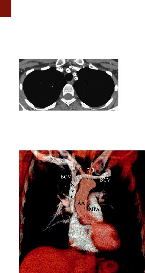
■ FIGURE 1-25 Structures in the thoracic inlet. A CT scan at the level of the thoracic inlet shows the right and left brachiocephalic veins (BCV), the right brachiocephalic artery (BCA) immediately anterior to the trachea, the left common carotid artery (CA) slightly to the left of the trachea, and the left subclavian artery (SC) more posteriorly. The esophagus lies posterior to the trachea.
The overall shadow of the great systemic veins and arteries as seen on a frontal chest radiograph extending from below the level of the thoracic inlet to the heart is known as the vascular pedicle. The width of the vascular pedicle is measured from the lateral edge of the SVC as it crosses the right main bronchus to a vertical line drawn inferiorly from the point where the left subclavian artery arises from the aortic arch (Fig. 1-27).45 The vascular pedicle in a normal upright posteroanterior chest radiograph measures less than 6 cm. Widening (>7 cm) may result from dilation of the great vessels (supine position, pregnancy, increased blood volume, left heart failure), mediastinal abnormality (lymph node enlargement, tumor, infection, or hemorrhage), or pleural disease.46
Mediastinum
Anatomy
The mediastinum separates the thorax vertically into two compartments and can be defined anatomically as the partition between the lungs. Anatomically, it can be divided into three compartments: anterior (prevascular), middle (cardiovascular), and posterior (postvascular).47
The anterior mediastinal compartment is bounded anteriorly by the sternum and posteriorly by the pericardium, aorta, and brachiocephalic vessels. It merges superiorly with the anterior aspect of the thoracic inlet and extends down to the level of the diaphragm. The compartment contains the thymus gland, branches of the internal mammary artery and vein, lymph nodes, the inferior
■ FIGURE 1-26 Structures in the thoracic inlet and mediastinum. A volume-rendering image from a CT scan shows the left and right brachiocephalic veins (BCV) as they course anterior to the brachiocephalic (1), common carotid (2), and left subclavian arteries
(3) to form the superior vena cava (SVC). Also note ascending aorta (AA) and aortic arch and the main pulmonary artery (MPA).
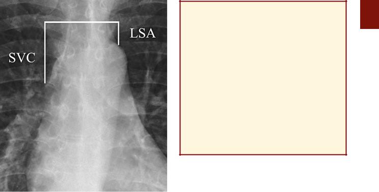
■ FIGURE 1-27 Vascular pedicle. A detail view from a posteroanterior chest radiograph shows the width of the vascular pedicle, which is measured from the lateral edge of the superior vena cava (SVC) as it crosses the right main bronchus to a vertical line drawn inferiorly from the point where the left subclavian artery (LSA) arises from the aortic arch. The normal width of the vascular pedicle on an upright posteroanterior chest radiograph is less than 6 cm.
sternopericardial ligament, and variable amounts of fat. On a chest radiograph the thymus is visible only in infants and young children, in whom it fills much of the anterior mediastinal space.
The middle mediastinal compartment contains the pericardium and its contents, the ascending and transverse portions of the aorta, the superior and inferior venae cavae, the brachiocephalic (innominate) arteries and veins, the phrenic nerves and the cephalad portion of the vagus nerves, the trachea and main bronchi and their contiguous lymph nodes, and the main pulmonary arteries and veins. The posterior mediastinal compartment is bounded anteriorly by the pericardium and the vertical part of the diaphragm, laterally by the mediastinal pleura, and posteriorly by the bodies of the thoracic vertebrae. It contains the descending thoracic aorta, esophagus, thoracic duct, azygos and hemiazygos veins, autonomic nerves, fat, and lymph nodes.
The anterior margin of the brachiocephalic vessels and ascending aorta is often difficult to identify on a chest radiograph. The distinction between the middle and the posterior mediastinal compartments is somewhat artificial and difficult to appreciate. Furthermore, anterior mediastinal masses often project over the heart. For these reasons and to facilitate localization of mediastinal abnormalities, it is preferable to classify abnormalities seen on radiographs into three groups based on the likelihood of their anatomic location: (1) the anterior mediastinum when a
C H A P T E R 1 ● Normal Chest Radiograph |
21 |
KEY POINTS: MEDIASTINUM
■Anterior
●Situated anterior to the pericardium, aorta, and great vessels
●Contains the thymus, lymph nodes, and fat
■Middle
●Contains the pericardium and its contents: Ascending and transverse portions of the aorta Superior and inferior venae cavae Brachiocephalic (innominate) arteries and veins Phrenic nerves and left recurrent laryngeal nerve
Trachea and main bronchi and their contiguous lymph nodes
Main pulmonary arteries and veins
■Posterior
●Posterior to the pericardium and anterior to the vertebrae
●Contains the descending thoracic aorta, esophagus, thoracic duct, azygos and hemiazygos veins, autonomic nerves, lymph nodes, and fat
mass is situated between the sternum and a line drawn along the anterior border of the trachea and the posterior border of the heart,48 (2) the middle-posterior mediastinum when a mass is located predominantly between this line and a line drawn 1 cm behind the anterior margin of the vertebral bodies, and (3) the paravertebral region when a mass is situated predominantly in the potential space adjacent to a vertebral body (Fig. 1-28). Although several authors refer to the latter region as the posterior mediastinum, this is incorrect. The mediastinum is limited posteriorly by the bodies of the thoracic vertebrae; abnormalities posterior to the anterior aspect of the vertebral body are not in the mediastinum but in the paravertebral region. Accurate assessment of the anatomic location of abnormalities is often not possible on radiographs but can readily be accomplished with CT or MRI.
Frontal Chest Radiograph
On a frontal chest radiograph the mediastinal shadow to the right of the trachea is formed by the right brachiocephalic vein and the SVC, and the contour of the lower mediastinal shadow is formed by the right atrium (Fig. 1-29; see also Fig. 1-26). The interface between the right brachiocephalic vein and the SVC is seen in almost all patients from the level of the medial end of the right clavicle to the level of the right bronchus (Fig. 1-29). The density of the SVC is generally less than that of the aortic arch, and its interface with the lung is normally slightly concave laterally.49 Increased opacity in the region of the SVC and the lateral convexity of its interface with the lung may result from increased size of the SVC (supine position, pregnancy, and right heart failure), paratracheal lymph node enlargement, a mediastinal mass, mediastinal hemorrhage, or a pleural abnormality.49
The trachea is normally bordered on its right lateral aspect by pleura covering the right upper lobe. Contact of the right lung in the supra-azygos area with the right
22 P A R T O N E ● Normal Chest
■ FIGURE 1-28 Mediastinal compartments on a lateral chest radiograph. A mass can be considered to probably lie in the anterior mediastinum if it is situated predominantly in the region in front of a line drawn along the anterior border of the trachea and the posterior border of the heart. A mass probably lies in the middle or posterior mediastinum if it is situated between this line and a line drawn 1 cm posterior to the anterior aspect of the vertebral bodies. Extrapulmonary masses posterior to this line are typically paravertebral in location.
lateral wall of the trachea creates a thin stripe of soft tissue density that is usually visible on frontal chest radiographs and is known as the right paratracheal stripe (Fig. 1-29).50 This stripe is formed by the right wall of the trachea, contiguous parietal and visceral pleura, and a variable quantity of mediastinal fat. The thickness of this stripe above the level of the azygos vein generally ranges from 1 to 4 mm. Widening of the paratracheal stripe (>5 mm) may be due to thickening of the tracheal wall by inflammation or tumor, paratracheal lymph node enlargement, mediastinal hemorrhage, or pleural disease.49,50 Widening of the paratracheal stripe is not a particularly sensitive sign in that it is present in only approximately 30% of patients who demonstrate paratracheal lymph node enlargement on CT.49
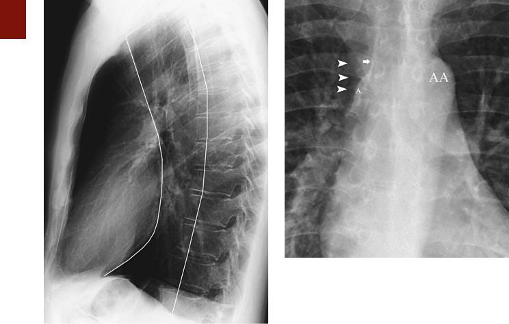
A slightly flattened elliptical opacity can frequently be seen in the region of the right tracheobronchial angle (Fig. 1-29). This opacity corresponds to the azygos vein being viewed tangentially as it enters the SVC. The transverse diameter of the azygos vein at this level is normally less
■ FIGURE 1-29 Normal right paratracheal region. A detail view from a frontal chest radiograph shows a normal mediastinum at the level of the aortic arch (AA). The right lateral border is delimited by the faint opacity of the superior vena cava (SVC) (arrowheads). The SVC normally has a straight outer contour and lower opacity than the aortic arch does. Note the right paratracheal stripe (arrow) and the azygos vein (A) at the level of the right tracheobronchial angle.
than 10 mm in the upright position and less than 15 mm in the supine position. Increased size of the azygos vein can result from systemic venous hypertension, portal hypertension, or obstruction of the SVC.
The azygos vein originates in the upper lumbar region at the level of the renal veins as a continuation of the right ascending lumbar vein. It passes into the thorax through the aortic hiatus medial to the right crus of the diaphragm. It then ascends to the right side or front of the vertebral column. Along its course the vein receives tributaries from the 5th to 11th intercostal veins on the right, the right subcostal vein, the right superior intercostal vein (which terminates in the azygos vein as it passes forward from the spine at the T4 or T5 level), the right bronchial veins, and the superior and inferior hemiazygos veins.51 It drains into the SVC. The esophagus is usually located slightly anterior and to the left of the azygos vein in the prevertebral region. Contact of the right lower lobe with the esophagus and the ascending portion of the azygos vein results in the azygoesophageal recess.51,52 This recess is frequently identified on a well-penetrated posteroanterior radiograph as an interface that extends from the diaphragm to the level of the azygos arch (Fig. 1-30). Typically, it is seen as a continuous arc concave to the right; however, in young adults, a straight or slightly dextroconvex interface may be present.53 A focal right-sided convexity of the azygoesophageal recess interface should raise suspicion of an underlying pathologic process such as a hiatal hernia,