

Sb95668
.pdfequal to 1.22 λ/A’, where λ is the radiation wavelength, and A’ is the beam diame-
ter at the focusing optical element) and several ring-shaped secondary maximums.
a) section b) intensity distribution
Fig. 1.9. Point spread function. In the Figure x’ is the transverse coordinate and I’ is the radiation intensity in the arbitrary units
The resolving ability (resolution) of optical system is its ability to resolve two point objects with the small distance between them. Sometimes there is also used the idea of the resolution limit, i.e. of the minimal distance between two point objects, which are still images as two separate objects. The most widely used resolution criterion, which is also known as the Rayleigh criterion, states that if the depth of the intensity depletion between the images of two point objects is equal to 20%, such points will be percept as the separate ones. The fulfillment of this criterion requires that in the image of two point objects (assuming they have equal intensities) the first minimum in the image of one point coincides with the maximum of the second image (see Fi.1.10). The Rayleigh criterion is used for estimation of resolution in astronomy telescopes and in some other optical systems (spectral systems, for instance). which are working with the pointor line-like objects.
Resolution of optical systems, imaging the objects with the complicated structure, is evaluated usually in terms of the Foucault criterion. In this case there are used the special test objects (mires), comprised by black and white lines of different width (Fig1.11).
Fig. 1.10. Resolution of two close points
11
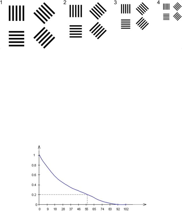
Fig. 1.11. Foucault mire (test object)
The resolution in this case is measured in lines per millimeter, and correspond to the minimal distance between the lines in the test-object frame, whose images can be yet resolved. Most usually in this case there is depicted the curve of frequency-contrast characteristics of the optical system (Fig.1.12), which illustrates the dependence of the image contrast upon the spatial frequency of the lines in testobject.
For the periodical objects the contrast is determined by the difference between the maximal and minimal intensities. The higher is the contrast, the better is the resolution of the small details of the image. For the 100% (absolute) contrast the image is very sharp and comprises black and white stripes. For the zero contrast all image is washed out to the uniform gray, and nothing can be distinguished.
contrast
spatial frequency, lines per mm
Fig.1.12. Frequency-contrast characteristic
One can not observe or register the image whose contrast is less than the threshold contrast of the sensitive film or sensor. So the resolution is determined for some specific contrast value – most usually, 0. 2. Usually the requirements to the optical system performance contain requirements to the highest spatial frequency, imaged with required contrast – for instanc e, 55 lines per mm and 20% (as in the Fig.1.12).
12
1.4. Aberrations
The limit of resolution by optical system is determined by its numerical aperture A – the ratio of optical system diameter and its foc al length, by radiation wavelength and also by aberrations. The aberrations lead to deviation of the opti-
cal ray trace from ideal and thus to aggravation of the image quality.
The structure and quality of optical image are determined by the joint action of two factors – of radiation diffraction and of ab errations. If the aberrations are small, the image quality is determined only by diffraction and is proportional to the product of numerical aperture and wavelength; in the absence of aberrations the image of the point object looks like the ideal Airy disk (see Fig.1.9). Such system
performance is known as the diffraction-limited one.
But in the case when aberrations are large, the diffraction effects become negligible, and we get the so-called geometry-limited optical system. Ray tracing in such system can be evaluated by means of geometry optics without account for diffraction. The transverse aberrations in such systems are much larger than the Airy
disk, and PSF shape and size are quite different from it.
Let us first of all briefly consider the origin of aberrations. In the so-called paraxial zone, where the angles α between optical rays and optical axis are small (when one can neglect the difference between α and sinα) there are no aberrations. In this zone one provide accurate tracing of optical ray through the system by use of thin and thick lens and of spherical mirror formulae. Such a system is sometimes called in ideal system. Outside the paraxial zone one has to take into account the real ray reflection or refraction at this or that optical surface, and thus its trace can deviate from the ideal case. Thus occurs the aberration. One can use for its description one of two equivalent languages, based either on wave aberration terms
or on lateral (transverse) aberrations.
The wave aberration is deviation of the real wavefront from the ideal one,
which is measured along the ray in terms of wavelengths (Fig.1.13):
W = |
n′ l |
(1.5) |
|
λ |
|||
|
|
The basic theory of wave aberration is rather complicated and cannot be discussed in this tutorial. To get some understanding of its origin let us consider the simplest case of imaging the point object by the concave mirror (point A and its image A’; see Fig.1.4).
13

Fig. 1.13. Wave aberration
In the case of ideal imaging, all optical rays, emitted from the point A, are finally to reach the image point A’. The absence of the wave aberration in this case requires that the optical length of all rays (ACA’, ADA’ and AEA’ in the Fig.1.4) are to equal. From mathematics we know that such equality is possible when the shape of the mirror surface is described by ellipse with the foci in the said points A and A’. However, in real systems most usually are employed the spherical mirror. Hence, in this case we shall obtain the wave aberration, whose magnitude is equal to double difference between the circle and ellipse. Similar conclusions are valid for the case of imaging of the infinitely distant object by the mirror (see Fig.1.2). In this case the use of parabolic mirror should have provided lack of aberrations, and the wave aberration if described by the double difference between the circle and parabola, i.e. by the 4th order parabola. Similar effects exist also in the case of lenses.
One can use also another language for description of aberrations – the language of lateral (transverse) and axial (longitudinal) aberrations. The lateral aberrations x’, y’ correspond to deviation of the real coordinates of the point, where ray crosses the image plane from the position of the ideal im-
age, estimated by means of geometry optics (see Fig.1.14). The axial aberration
S’ corresponds to longitudinal shift of the point, where the ray crosses the optical axis from the ideal value.
The languages of wave, lateral and axial aberrations are the different forms of presenting one and the same effect (lateral aberrations can be presented in terms
14
of wave aberration derivatives). The language of wave aberrations is more convenient when the system provides high image quality, while robust distortions are better explained in terms of lateral ones.
One can distinguish the monochrome and chromatic aberrations. The origin of the monochrome aberrations was explained earlier. Chromatic aberrations occur in lens systems due to dependence of refraction index of lenses upon the radiation wavelength. Hence focal distances of lenses change with wavelength, resulting in specific rainbow-like distortions of the image. Mirrors do not introduce chromatic aberrations.
There are several approaches to correction of optical aberrations. Telescopes often use instead of spherical the mirror with more complicated (aspheric) surface
– parabolic or hyperbolic. Mirrors and lenses with aspheric surfaces are sometimes used in other systems as well, but in this case are more often providing mutual compensation for aberrations by use of specific combination of optical elements. In this case special mathematical methods and corresponding software are used, calculating and optimizing the image quality by provision of specific shapes of lenses and mirrors and of distances between elements. Chromatic aberrations are corrected by use of combination of several lenses, made of different optical glasses. These glasses reveal different spectral dependence of the refraction index (dispersion) and thus one can equalize the focal lengths of the overall system for different wavelengths.
2. Telescopes
The telescope is the optical system, providing imaging (usually with magnification) of the remote object. The word origins from Greek – τῆλε – tele – far away, remote, and σκοπεῖν – scopos – to look. The telescopes are used in astronomy, and also as spyglasses, monoand binoculars and as various periscopes, range finders and geodetic devices (theodolites, levels and others), and also collimators and autocollimators.
2.1. Refractors
The lens telescopes, which are also known as spyglasses, were the first optical systems, invented in history; before them only single lenses were used as spectacles or as magnifying glasses. Two basic schemes of refractors (i.e. lens telescopes), which are widely used now, were invented practically simultaneously at
15
the very beginning of 17th century by Kepler and by Galileo, and are known under their names.
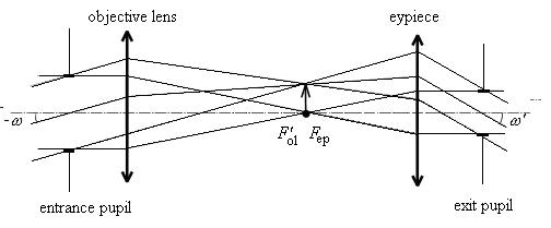
Fig. 2.1. Kepler tube
All telescopes comprise two components – the object ive lens and the eyepiece (ocular). In the Kepler tube both of them are converging, and the rear focus of the objective lens coincides with the forward focus of the eyepiece (Fig.2.1). Hence both object and image are positioned at infinity; these feature is basic for all telescopes. The objective lens creates the real inverted image of the object in its focal plane, and the eyepiece makes it possible to see this image by eye. Usually the eyepiece focal point can be tuned so as to compensate for the humane eye defects – myopia or hyperopia.
Since the object and image are at infinity, the input beam is considered to be a parallel one. For the axial object this beam is parallel to main optical axis, while for the objects, which are not on system axis, the beams will be inclined with re-
spect ot this axis in the angle ω. These beams will leave the telescope at the angle ω‘.
Let us consider main features of the telescopes. The visible magnification of the telescope is equal to the ratio of the focal distance of the objective lens to that of the eyepiece
Γ = |
tgϖ ′ |
= − |
f |
|
|
|
le |
. |
(2.1) |
||
tgϖ |
f |
||||
|
|
|
ep |
|
|
For positive magnification the image is non-inverted, while for the negative it is inverted. The magnification is measured in times, and is written as, say, 8x. This magnification can vary from 8x or even less for spyglasses and binoculars to several hundreds and even thousands for the astronomic telescopes.
The angular field of vision of the telescope depends upon the field of the eyepiece and of the visible magnification tgω = tgω’/Γ. Since the angular field of
16

vision of eyepiece is usually some 50 - 70°, while the visible magnification of the majority of non-astronomy telescopes is usually limited by some 10х – 15 х, the input field of vision is usually less than 10°. The d iameter of the exit pupil1 in such devices is determined by humane eye pupil. This eye pupil is to be positioned in the plane of the exit pupil of the system, and in this case all the light, reaching the objective lens, reaches the eye. The diameters of the entrance and exit pupils are coupled by the simple ratio D = ΓD’; one has to remember that in the daytime the humane eye pupil has the diameter of 2-5 mm, while in the nighttime it is equal to 5-7 mm.
The limit of angular resolution by telescope depends upon the entrance pupil λ = 0.5 μm, the angular resolution of
Ψ = 1.22 |
λ |
= |
120′′ |
. |
(2.2) |
|
|
||||
|
D D |
|
|||
Here D is the entrance pupil diameter, measured in millimeters. For instance, for
D = 6000 mm the limit of resolution would be equal to 0.02”. If the telescope is working with the humane eye its resolution is limited by the eye resolution which is equal to approximately 1’. Hence, if one want to employ completely the telescope resolution for eye observations, the useful visible magnification of the telescope should be equal to:
Γ = |
Ψeye |
= 0.5D . |
(2.3) |
Ψ |
The Kepler system provides image inversion, and this is a disadvantage. It is not very important in astronomy, but is obviously inconvenient when using such system as a spyglass for terrestrial observations. So one has to use the image inversion, which can be provided either by additional lens system (Fig.2.2) or prism system (Fig.2.3), positioned between the objective lens and eyepiece. The fist approach leads to increase of the overall system length, while the second one is, bice versa, shortening it, but at the same time increases the system weight and cost, and also makes its adjustment much more difficult. The second approach is used in the binoculars with the large magnification.
1 The entrance and exit pupils of the telescope are the images of the aperture diaphragm by the components of telescope, placed before the aperture and after it correspondingly. The aperture diaphragm is the “narrowest” place in the overall optical system – some mounting or scree n with opening, limiting the diameter of the beam, transfoemed by the system.
17
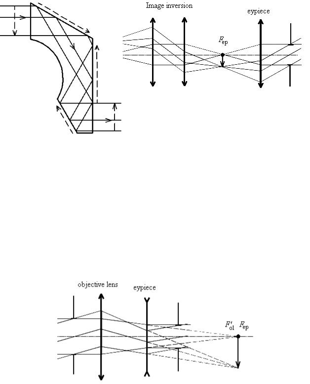
Fig. 2.2. Lens image inversion
At the same time the presence of real image in the Kepler tube focus can be treated as an advantage. One can position in the focal plane the graticule – some glass plate with scale on it. One can use this graticule for exact measurement of angles and distances to the objects, whose size is known. Kepler tubes are used as the modest size astronomy telescopes, as spyglasses and binoculars, in range finders and other geodetic instruments, and also for collimation of radiation (expansion of beam with reduce of its divergence)
in various collimators and autocollimators.
Fig. 2.3. Prism image inversion.
Fig.2.4. Galileo tube
In the Galileo tube the objective lens is also converging while the eyepiece is diverging (Fig.2.4). The rear focal point of the objective lens coincides with the forward focus of the eyepiece. Hence no intermediate real image is constructed in such a system.
18

The Galileo tube is shorter than the Kepler one and provides the noninverted image. These are the advantages, but Galileo tube has also some disadvantages. First of all, it has narrow field of vision, which becomes narrower when magnification is enlarged. Also the lack of the intermediate real image prevents the use of the graticule and thus the use of such design in measurement systems. Hence the Galileo system use is limited mainly by small-size systems like theatre binoculars, viewfinders etc., and also by collimators for high-power laser radiation, where light focusing, existing in Kepler tube, can lead to optics’ damaging and to laser spark production.
2.2. Reflectors
Mirror telescopes, known as reflectors, provide imaging by light reflection from the spherical or parabolic mirror, known as the main mirror or primary mirror. Then the light is reflecting from secondary (tertiary etc.) mirrors or is collected by the eyepiece. The most widely used is the so-called Cassegrain reflector scheme, shown in the Fig.2.5. In such a scheme the secondary mirror sends the radiation to the focal unit of the telescope (or eyepiece) through the opening in the primary mirror,
Fig. 2.5. Cassegrain scheme
One can place in the focal plane (focal unit) of the telescope various photosensitive media or elements (photographic plate, CCD-matrix, spectrograph etc.), registering the image, or, if necessary, use the eyepiece of image observation in the same manner as in the Keppler tube. In such a telescope the distance from the last
19
surface (primary mirror) to the focal plane is much shorter than the focal length, so such a telescope can be much shorter (and lighter) than the similar lens telescope.
If one wants to increase the telescope magnification, preserving at the same time the exit pupil diameter, he has to enlarge the objective diameter. The larger is its diameter, the larger is the telescope’s optical primary (i.e., light energy collection ability) and the finer is its resolution, and thus one can image the very remote and weak stars and galaxies. From the technology point of view it is much easier to enlarge the mirror diameter than that of lens (in this case the glass inhomogeneity is not very important, and in addition large size mirrors are much lighter than lenses), and hence all large astronomical telescopes are employing the reflector concept. Mirrors are free from chromatism, which is also an advantage of the reflectors.
The largest current ground-based telescopes have a primary mirror of between 6 and 11 meters in diameter. In this generation of telescopes, the mirror is usually very thin, and is kept in an optimal shape by an array of actuators (see active optics). This technology has driven new designs for future telescopes with diameters of 30, 50 and even 100 meters.
Relatively cheap, mass-produced ~2 meter telescopes have recently been developed and have made a significant impact on astronomy research. These allow many astronomical targets to be monitored continuously, and for large areas of sky to be surveyed. Many are robotic telescopes, computer controlled over the internet, allowing automated follow-up of astronomical events.
Initially the detector used in telescopes was the human eye. Later, the sensitized photographic plate took its place, and the spectrograph was introduced, allowing the gathering of spectral information. After the photographic plate, successive generations of electronic detectors, such as the charge-coupled device (CCDs), have been perfected, each with more sensitivity and resolution, and often with a wider wavelength coverage.
Current research telescopes have several instruments to choose from such as: imagers, of different spectral responses; spectrographs, useful in different regions of the spectrum; and polarimeters, that detect light polarization.
The phenomenon of optical diffraction sets a limit to the resolution and image quality that a telescope can achieve, which is the effective area of the Airy disc, which limits how close two such discs can be placed. This absolute limit is called the diffraction limit (and may be approximated by the Rayleigh criterion, Dawes limit or Sparrow's resolution limit). This limit depends on the wavelength
20