

S E C T I O N 3 System Design Requirements
1 General
1.1Functionality
i)The DC power distribution system is to distribute sufficient power to the intended loads of the vessel during all operational modes (i.e., normal sea going, cargo handling, harbor maneuver and emergency operations.).
ii)The DC power distribution system is to provide appropriate protection for the electrical equipment and personnel who operate the equipment during normal operation, maintenance and fault conditions.
1.3Voltage Variations
The design is to comply with the requirements for Voltage Variations for DC Distribution Systems as per 4-8-3/1.9 of the Marine Vessel Rules. The applicable table is listed below for convenience.
TABLE 1
Voltage Variations for DC Distribution Systems
Voltage Variations for DC Distribution Systems (such as systems supplied by DC generators or rectifiers)
|
Parameters |
Variations |
Voltage tolerance (continuous) |
±10% |
|
Voltage cyclic variation deviation |
5% |
|
Voltage ripple (AC rms over steady DC voltage) |
10% |
|
Note: |
See also IEC 60092-101 |
|
1.5Power Quality
i)Any harmonics created within AC systems is to be within the limits specified in 4-8-2/7.21 of the
Marine Vessel Rules.
ii)Considerations are to be taken when ripple currents flow between the DC power sources and connected loads. Also voltage ripples and noise developed from the converters (e.g., generator rectifier, AC load inverter) are to be mitigated so that they do not impact the normal system operation. See details in Section 3, Table 1 of this Guide.
iii)A means of monitoring power quality is to be provided to measure, record, and report the above conditions and any other power disturbances (e.g., spikes, sags, surge, etc.). See also 3/15.3.3 of this Guide.
1.7Earthing
i)When the DC distribution system is ungrounded, means of detection of the system insulation condition is to be provided. Those means of detection are to be rated for the system voltage.
ii)A means for insulation monitoring and alarm is to be provided in accordance with 4-8-3/Table 5 (item 3) of the Marine Vessel Rules for the purpose of detecting earth faults.
ABS GUIDE FOR DIRECT CURRENT (DC) POWER DISTRIBUTION SYSTEMS FOR MARINE AND OFFSHORE APPLICATIONS . 2018 |
7 |

Section 3 System Design Requirements
1.9Computer-Based Systems
The computer-based systems controlling the DC power distribution system and associated protection systems are to comply with requirements in Section 4-9-3 of the Marine Vessel Rules.
1.11Materials
The electrical equipment is to be constructed in accordance with 4-8-3/1.7 in the Marine Vessel Rules.
1.13Clearance and Creepage Distances
The equipment is to be designed and manufactured with electrical clearance and creepage distances for the rated voltage in order to prevent electrical failure or insulation breakdowns. The equipment is to comply with the applicable sections of IEC 61439-1 or other recognized standards.
1.15Enclosures
Electrical equipment is to have a degree of enclosure for protection against the intrusion of foreign objects and liquids, appropriate for the location in which it is installed as required in 4-8-3/1.11 of the Marine Vessel Rules.
3 Electrical Power Sources
The electrical power sources of the DC power distribution system are to be described in the system specifications, including but not limited to generators, fuel cells, and other renewable sources if applicable. The electric power sources are to be connected to the DC bus directly or through power electronic converters (such as AC/DC rectifiers, DC/DC converters). The electrical power sources are to be protected against faults with protective devices such as DC circuit breakers, fault current limiting/bypass converters, solid state switches and fuses, or a combination of the same.
Section 3, Figure 1 below shows the general system block diagram of a low voltage DC power distribution system.
FIGURE 1
Example of a DC Power Distribution System Block Diagram Concept
8 ABS GUIDE FOR DIRECT CURRENT (DC) POWER DISTRIBUTION SYSTEMS FOR MARINE AND OFFSHORE APPLICATIONS . 2018

Section 3 System Design Requirements
5 Energy Storage Systems (ESS)
If Energy Storage Systems are installed in the onboard DC power distribution system, the following requirements are to be followed:
i)Any ESS (such as batteries, supercapacitors, flywheels, etc.) discharged to and charged by the DC bus is to be protected against electrical faults (including short circuit currents) in the system.
ii)Any ESS, which is discharged to and charged by the DC bus, is to be provided with means of isolation for maintenance purposes.
iii)Any internal fault in an ESS is not to affect the rest of the system.
iv)Single failure of an ESS, when it serves as one of the primary power sources, is not to result in total loss of vessel normal operation capability (including DP functions as applicable).
v)Lithium batteries installed in DC distribution systems are to be in accordance with the ABS Guide for Use of Lithium Batteries in the Marine and Offshore Industries.
vi)Conventional batteries (e.g., lead acid, alkaline types) installed in DC distribution systems are to be in accordance with the Marine Vessel Rules and the MOU Rules.
vii)Supercapacitors installed in DC distribution systems are to be in accordance with the ABS Guide for Use of Supercapacitors in the Marine and Offshore Industries.
7 External or Shore Power Supply Connection
Where arrangements are made for the supply of electricity from a source on shore or other external source, the requirements in 4-8-2/11.1 in the Marine Vessel Rules and/or 4-3-2/7.7 in the MOU Rules are to be complied with as applicable. In addition, the following requirements are to be followed as applicable.
i)The type of shore supply (AC or DC) is to be considered in the design of the shore connection. Thus, converters and/or associated transformers are to be provided for external power supply as applicable.
ii)Associated protective and isolation devices for shore power are to be provided. These devices are to be considered in the vessel protection and coordination study.
9 Power Distribution
9.1Isolation and Disconnection Means
i)Where the main source of electrical power is necessary for propulsion of the vessel, the main DC bus is to be subdivided into at least two sections, which are to be connected by DC circuit breakers or other approved means.
ii)The rating of any disconnecting devices (other than bus-tie disconnecting means) is to be equal to or higher than the voltage and current ratings of connected load. Such device is to have an indicator for its open or closed position. The bus bar connections are to comply with the requirements in 4-8-3/5.5.1 of the Marine Vessel Rules.
iii)Appropriate operational measures or interlocks are to be provided to prevent access to energized circuits during maintenance, except when a risk assessment shows such a condition is safe for the operator.
iv)Identification plates for feeders and branch circuits are to be provided and are to indicate the circuit designation and the rating or settings of the fuse or circuit breaker of the circuit.
ABS GUIDE FOR DIRECT CURRENT (DC) POWER DISTRIBUTION SYSTEMS FOR MARINE AND OFFSHORE APPLICATIONS . 2018 |
9 |

Section 3 System Design Requirements
9.3DC Bus
9.3.1General
The DC bus is to be sized and arranged such that the temperature rise will not affect the normal operation of electrical devices connected to it. The DC bus is to be sized based on the combined rated output current from the converters supplied by each power source (this includes generators, fuel cells, and ESS, as applicable). Alternative bus sizing methods may be considered.
The DC bus is to be properly sized to withstand the short circuit current available on the DC bus.
Note: The DC distribution system design may possess additional protective circuits that will block the current contributions of the inverter modules and downstream AC loads in the event of a short circuit at the DC bus. If such additional protective circuits are provided, the details of the operation of such a protective circuit needs to be considered when calculating the short-circuit rating of the DC bus.
9.3.2Bus Ducts
If bus ducts are used to distribute and control electrical energy throughout the vessel, the bus ducts are to be designed, constructed, and installed in accordance with IEC 61439-6 or IEEE C37.23 or other recognized standard.
9.3.3Cables
Where cables are used in lieu of bus ducts, cables are to be designed, constructed, and installed in accordance with 4-8-2/7.7, 4-8-3/9, and 4-8-4/21 of the Marine Vessel Rules, as applicable. Other recognized standards may also be acceptable.
9.3.4Protective Devices
The DC bus is to incorporate protective devices against fault conditions (e.g., short circuit, overcurrent).
9.3.5DC Bus Protection Coordination
The bus protection function settings are to be coordinated with other protection function settings.
9.3.6Overload Protection
Circuit breaker, fuses, switches, and power electronic converters used for overload protection are to be provided for the specific application (e.g. motor circuit, lighting circuit, distribution board circuit, etc.) in accordance with 4-8-2/9.5 of the Marine Vessel Rules, IEC 60092-202 and IEC 61892-2 as applicable.
11 Power Electronic Converters (PEC)
In addition to the applicable requirements of semiconductor converters in the 4-8-3/8 of the Marine Vessel Rules, power electronic converters (AC/DC, DC/AC, DC/DC conversions) for DC power distribution system are to comply with the following requirements.
i)The design of the converter is to be in accordance with a recognized standard (e.g., IEC standards 60146 and 62477)
ii)Each power electronic converter is to be provided with the status indication that includes but is not limited to: power input and power output, temperature, and overload. Additional functions, such as alarms and shutdowns, may be necessary as determined in the risk assessment process.
iii)Converter control software is to comply with Computer-based Systems requirements as per Section 4-9-3 of the Marine Vessel Rules.
iv)Power electronic converters are to be designed to withstand foreseeable abnormal conditions (e.g., transient overvoltage and overcurrent) from the DC bus without changes in their characteristics and functionalities.
v)The short-circuit contributions of internal capacitors in converters are to be considered in the sizing of protective devices and in the system protection coordination study.
10 ABS GUIDE FOR DIRECT CURRENT (DC) POWER DISTRIBUTION SYSTEMS FOR MARINE AND OFFSHORE APPLICATIONS . 2018

Section 3 System Design Requirements
vi)The pre-charging of the converter internal capacitor before connecting the load to the energized DC bus, and the recharging of the converter internal capacitors during and after short circuit is to be managed to mitigate the risk of damage to converter components caused by transient currents.
vii)For vessel with an integrated electrical propulsion systems, generator converters (such as AC generator rectifiers) operating in parallel are to be able to conduct load sharing under the control of a Power Management System. Other means of control for load sharing may be accepted provided that overload of generators is prevented.
viii)Where converters are arranged to provide protection against electrical faults, a disconnecting method is to be provided to isolate the converter from its source. In case of any converter’s internal failure, a backup protection method is to be provided. In such arrangement, the design is to demonstrate that the converter will operate within the safe operational specification under normal and fault conditions.
ix)Design of the cooling system for power electronic converters is to comply with 4-8-3/8.5.8 of the
Marine Vessel Rules.
13 Power Management System (PMS)
A power management system (PMS) is required to be installed onboard for vessels having notations such as DPS, ACCU, etc., as indicated in the Marine Vessel Rules and the MOU Rules, and the ABS Guide for Dynamic Positioning Systems.
Consideration is to be given to the installation of a PMS on board to provide monitoring, control and protection functions to maintain sufficient electrical power available on various operation modes.
15 Protection Coordination and Selectivity
15.1General
i)In general, the DC system protection is to be accomplished by the use of DC circuit breakers, fuses, converter controls, solid state switches, and other technologies that achieve selectivity and appropriate protection coordination of such DC power systems.
ii)The protection system of the DC distribution system is to be able to detect and locate the fault, and isolate the faulted equipment or subsystems from the rest of the DC system.
iii)The design of the protection system is to demonstrate that the protective device nearest to the fault will open first and thereby isolate the faulted portion from the rest of the system.
15.3Short-Circuit Currents and Fault Conditions within DC Systems
15.3.1Consideration of Fault Current Contributions
In general, the contributions of short-circuit current on the DC bus are from:
i)Generators (e.g., through the rectifier modules)
ii)Converters (e.g., from the internal capacitors within the inverter modules)
iii)AC motor loads (e.g., fed through the inverter modules)
iv)DC loads (e.g., fed through the converter modules)
v)Downstream AC sub-distribution boards
vi)Energy storage systems (batteries, supercapacitors, flywheels, etc., if installed)
vii)The healthy side of the DC bus segments before interruption by the DC bus-tie breaker (e.g., in cases where the DC bus is operated in a closed-ring mode).
ABS GUIDE FOR DIRECT CURRENT (DC) POWER DISTRIBUTION SYSTEMS FOR MARINE AND OFFSHORE APPLICATIONS . 2018 11

Section 3 System Design Requirements
15.3.2Short Circuit Calculation
In order to properly size protective devices and equipment connected to the DC bus, short circuit current calculations are to be conducted.
Due to different converter configurations used in the DC distribution system, methods of calculation are to be based on steady state and transient state as needed. Application of standards (e.g., IEC 61660, IEEE 946) and/or other modeling and simulation approaches are to be documented.
15.3.3Transient Overvoltage
Fault types or switching operations and their locations within the DC systems may lead to other events such as the development of overvoltage or transient voltages. Therefore, overvoltage transient studies are recommended in order to assess and protect the entire electrical systems from those risks. The method and analysis utilized for transient overvoltage protection is to be submitted for ABS review. Refer to IEC 60364-4-44 for specific requirements of protection against transient overvoltage.
15.5Selective Protection Strategy
15.5.1General
i)The requirements to provide a selective protection strategy is to minimize equipment damage and power disruption of the DC power distribution system. Selectivity can be achieved through the integration of different protective devices and the use of software within sections or zones of the electrical network. See 3/15.5.2 through 3/15.5.4 below.
ii)Other strategies or approaches to demonstrate a selective protection scheme are also acceptable to ABS provided that appropriate documentation is submitted for review.
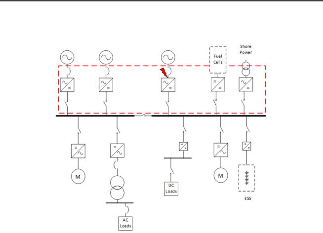
15.5.2Protection within Zone Upstream of DC Bus
For fault conditions within this electrical network area, the following as a minimum is to be considered:
i)Fault current detection functionalities are to be provided within a generator protection unit and/or within the generator converter as applicable.
ii)Protective devices between the DC bus and the electrical power sources are to be properly sized and set up to trip and isolate the fault.
iii)In an event of fault in the generator, the failed generator is to be de-excited.
iv)The Power Management System is to reduce load in order to prevent blackout caused by overloading the remaining running generators.
v)The power electronic converter on the power generation side is to prevent reverse power flow from the DC bus to the generators.
vi)Where converters are utilized to protect the electrical power sources, a back-up short circuit protection method is to be provided in case of an internal fault in the power electronic converter (such as AC/DC rectifier modules) between each single generator and the DC bus. As an alternative to a backup method, the designer is to demonstrate the same level of protection in their design by submitting a description of how this is achieved.
12 ABS GUIDE FOR DIRECT CURRENT (DC) POWER DISTRIBUTION SYSTEMS FOR MARINE AND OFFSHORE APPLICATIONS . 2018
Section 3 System Design Requirements
FIGURE 2
Short Circuit Fault Location 1 – Upstream of DC Bus (example schematic for reference only)
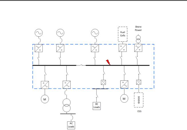
15.5.3Protection within Zone on DC Bus
For fault conditions within this electrical network area, the following as a minimum is to be considered:
i)A means to detect fault current is to be provided in the protective devices connecting to the DC bus.
ii)The Power Management System is to react accordingly, after the activation of the generator protection unit, to prevent a blackout condition.
iii)The arrangements of the DC bus-tie disconnecting means and the protection system are to isolate the faulted DC bus section. The system is to be so arranged that if there is a fault on one section of the DC bus, the other healthy section(s) of the DC bus will be in operation after all protection systems have operated.
iv)For DC distribution systems supplied by AC generators, information including type test reports or proof by simulation is to be provided from the integrators/manufacturers to demonstrate:
a)Coordination between the AC generator protection and rectifier module protection during a short-circuit current on the DC bus.
b)Ability of the rectifier module to withstand damage during a short-circuit current on the DC bus.
ABS GUIDE FOR DIRECT CURRENT (DC) POWER DISTRIBUTION SYSTEMS FOR MARINE AND OFFSHORE APPLICATIONS . 2018 13
Section 3 System Design Requirements
FIGURE 2
Short Circuit Fault location 2 – On DC Bus (example schematic for reference only)
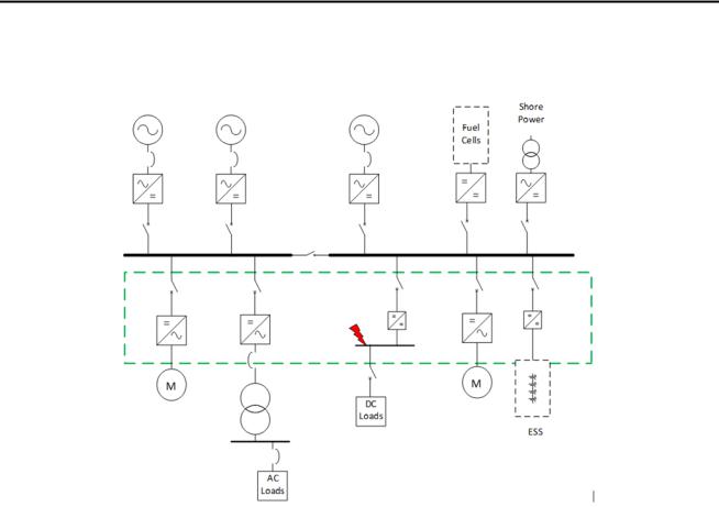
15.5.4Protection within Zone Downstream of DC Bus
For fault conditions within this electrical network area, the following as a minimum is to be considered:
i)The protective devices on the load side are to detect the fault and trip accordingly.
ii)In the event of an internal fault in the power electronic converter module between the DC bus and the load, a back-up short circuit protection means is to be provided between the DC bus and the converter (such as fast-acting semiconductor fuses).
iii)Coordination among the protective devices used for the different converter module capacitors is to be considered during the system protection coordination design.
iv)In the event of a fault inside of a load converter module, only the fuses (or other protective device) protecting this particular module will trip, and other load converter modules connected to the same DC bus section are not to be affected.
14 ABS GUIDE FOR DIRECT CURRENT (DC) POWER DISTRIBUTION SYSTEMS FOR MARINE AND OFFSHORE APPLICATIONS . 2018
Section 3 System Design Requirements
FIGURE 4
Short Circuit Fault Location 3 – Downstream of DC Bus (example schematic for reference only)
17 Risk Assessment
The primary objective of the risk assessment is to identify technical risks and uncertainties associated with the proposed DC power distribution system and control system design and its incorporation on a vessel. The risk assessment is to demonstrate the vessel’s safety and the continuity of power supply in case of failure of any part of the system.
A Failure Mode and Effects Analysis (FMEA) study is typically implemented, but alternatively other risk assessment techniques may also be adopted. The use of other risk assessment techniques should be discussed with ABS prior to performing the risk assessment. The risk assessment is to be carried out in accordance with the ABS Guidance Notes on Risk Assessment Application for the Marine and Offshore Oil and Gas Industries, ABS Guidance Notes on Failure Mode and Effects Analysis (FMEA) for Classification, or other ABS-recognized industry standards (e.g., IEC 60812).
All foreseeable hazards, their causes, consequences (local and global effects), and associated risk control measures are to be documented. The DC power distribution system risk assessment report is to be submitted for ABS review, and at a minimum is to address the following aspects:
i)All normal and foreseeable abnormal operating conditions
ii)Equipment layout, arrangement, and location
iii)Mechanical faults, electrical faults and human errors and associated alarms (e.g., earth fault, fire, flooding, cooling/heating failure, and operation exceeding the designed operating parameters)
iv)Software development, version updating, compatibility, and integrity
v)Electrical power system protection philosophy (e.g., loss of cooling power, loss of heating power, loss of control power, loss of power input to main supply, loss of power supply, loss of power on a single DC bus segment, DC breaker or other protection device failure, earth fault, short-circuit fault)
ABS GUIDE FOR DIRECT CURRENT (DC) POWER DISTRIBUTION SYSTEMS FOR MARINE AND OFFSHORE APPLICATIONS . 2018 15

Section 3 System Design Requirements
vi)Control component failure (e.g., temperature/pressure sensor failure, generator rectifier/ load inverter failure, DC bus-tie failure, main propulsion thruster drive failure, DP function thruster drive failure, loss of communication)
vii)Electrical shock precautions. The consideration that personnel cannot access energized equipment is to be given to the system design and equipment layout.
viii)Energy storage devices hazards if applicable (e.g., lithium-ion battery thermal runaway, see details of ESS operation hazards in the Lithium Battery Guide and the Supercapacitor Guide).
16 ABS GUIDE FOR DIRECT CURRENT (DC) POWER DISTRIBUTION SYSTEMS FOR MARINE AND OFFSHORE APPLICATIONS . 2018