

МИНОБРНАУКИ РОССИИ
САНКТ-ПЕТЕРБУРГСКИЙ ГОСУДАРСТВЕННЫЙ
ЭЛЕКТРОТЕХНИЧЕСКИЙ УНИВЕРСИТЕТ
«ЛЭТИ» ИМ. В.И. УЛЬЯНОВА (ЛЕНИНА)
Кафедра РТЭ
Отчет по индивидуальному заданию №2
По дисциплине «Микроволновая электроника»
Студент гр. 9201 |
|
Рауан М. |
Преподаватель |
|
Иванов В.А. |
Санкт-Петербург
2022
Task 1.
From the presented list,
select "your" device according to the rule
 .If your number exceeds the number 11, then

For this device, describe:
Construction
The principle of operation using the hydrodynamic approach and the formula:
 ,
quantum approach and individual radiation of charged particles.
,
quantum approach and individual radiation of charged particles.Estimate the size of the device if it operates at a frequency of

Power, gain, other parameters - choose yourself, according to the typical parameters of this type of devices
Answer:
Construction
An ubitron (ubitron – Undulator Beam Interaction) is an amplifying electronic device in which an electron beam interacts with a fast electromagnetic wave propagating in a waveguide. The ubitron was first described by R. Phillips (the USA) in 1960. It’s design is schematically represented in Fig.1.1. Electron gun 1 creates and accelerates an electron beam. Waveguide system 3, with input 2 and output waveguides 5, ensures the propagation of a fast wave. The magnetic system, including permanent magnets 4, creates a periodic magnetic field distribution and is called an undulator or a wiggler. Electron collector 6 receives the electron beam.

Fig. 1.1. Scheme of ubitron design.
Hydrodynamic approach

Fig. 1.2. An undulator
Fig. 10.3.2 shows the
undulator magnetic system formed by a number of prismatic magnets.
The arrows point in the magnetization direction of the prismatic
magnets. The function
 (x)
in such an undulator is of periodic nature and can be approximated
using the formula:
(x)
in such an undulator is of periodic nature and can be approximated
using the formula:

Quantum approach
Where b is the magnetic field
period of the undulator;
 is
the amplitude of the magnetic field.
is
the amplitude of the magnetic field.
Equations of motion of the electron beam in the ubitron undulator:


Where b – period of magnetic
field;
-
field amplitude;
 -
the average longitudinal velocity of electrons
-
the average longitudinal velocity of electrons
 -
relativistic factor
-
relativistic factor

Fig. 1.3 the motion of the electron beam in undulator
it is assumed that


Because of
 consequentely

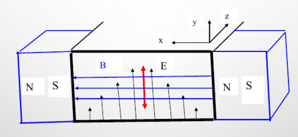
Fig. 1.4 interaction of electrons with the waveguide field in the ubitron
The
 wave
is used, the E field has only one transverse component
wave
is used, the E field has only one transverse component
 ,
with which the electrons oscillating along the y axis interact
,
with which the electrons oscillating along the y axis interact
Estimation the size of the device:
Operating frequency: f=21 GHz
Anode Voltage: Ua=200 V
The density of the constant
convection current from the cathode:
The maximum value of the span angle: θ=2 π
Knowing that the angle of the span can be determined:

Sources: Microwave electronics pdf.pdf
Лекция 9 н Гирорезонансные Релятивистские.ppt (yandex.ru)
Task 2.
Devices with quasi-static control. Triode.
Calculate the static angles of
flight of charge carriers in the cathode-grid gap of a triode
operating in one of the modes A, B or C (choose yourself). The phases
of departure from the cathode are set from 0 to
 .
(Consider the voltage on the electrodes unchanged during the flight).
.
(Consider the voltage on the electrodes unchanged during the flight).
Operating frequency:
 (MHz),
cathode-grid distance: 0.1*
(MHz),
cathode-grid distance: 0.1* (mm)
, constant voltage at the anode 50*
(V),
grid permeability 0.01*(
(mm)
, constant voltage at the anode 50*
(V),
grid permeability 0.01*(
 ).
Calculate the interaction coefficient for these angles. Using the
results obtained, explain why triodes are ineffective at high
frequencies.
).
Calculate the interaction coefficient for these angles. Using the
results obtained, explain why triodes are ineffective at high
frequencies.
Given:
Operating mode: A
Operating frequency: f=1400 MHz
Cathode-grid distance: d=0,1mm
Constant voltage at the anode: Ua=50 V
Mesh permeability: D=0,14
Solution:
I have chosen the mode A,
which is characterized by using only the rectilinear part of the
control characteristic lying in the region
 .
This ensures minimal distortion of the shape of the cathode and anode
currents in relation to the shape of the control voltage.
.
This ensures minimal distortion of the shape of the cathode and anode
currents in relation to the shape of the control voltage.
The voltage range for Class A is from a voltage a litter more than the locking voltage to 0.
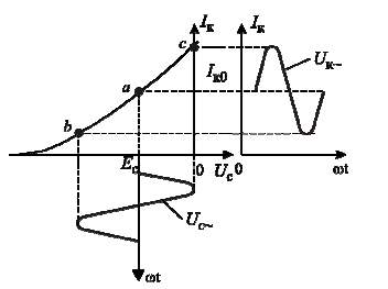
Fig 2.1 Cathode current modulation in Class A mode
We can calculate Ucl, using the following formula:


Suppose, that
 (V)
(V)
Let’s calculate electron flight angle, using following formulas:

 = 1,48 rad
 = 0,56 rad
Let 's find the coefficients of interaction by using following formulas:


Why triodes are inefficient at high frequencies:
As we can see from calculations an increase in frequency leads to an increase in the span angle, the input conductivity is related to the span angle by a quadratic dependence, and thus an increase in the span angle significantly increases the input conductivity. The increase in input conductivity increases losses, it means, the input power and efficiency decreases. Consequently, triodes are not effective at high frequencies.
Answer:


Sources: Сушков А.Д., Вакуумная электроника: Физико-технические основы.