

Ä |
|
CHIME WARNING/REMINDER SYSTEM 8U - 1 |
|
CHIME WARNING/REMINDER SYSTEM
CONTENTS
|
page |
BODY CONTROLLER REPLACEMENT . . . . . . . |
. . 4 |
CHIME MODULE REPLACEMENT AA and |
|
AP BODIES . . . . . . . . . . . . . . . . . . . . . . . . . . |
. . 4 |
CHIME SYSTEM DIAGNOSISÐAA AND |
|
AP BODIES . . . . . . . . . . . . . . . . . . . . . . . . . . |
. . 2 |
CHIME SYSTEM DIAGNOSISÐAC, AG, |
|
AJ AND AY BODIES . . . . . . . . . . . . . . . . . . . |
. . 3 |
CHIME WARNING/REMINDER SYSTEM TEST |
. . 2 |
GENERAL INFORMATION
WARNING: ON VEHICLES EQUIPPED WITH AN AIR BAG REFER TO THE AIR BAG PORTION OF THIS SECTION FOR STEERING WHEEL OR SWITCH REMOVAL AND INSTALLATION PROCEDURES.
BUZZER SYSTEM
The seat belt warning system uses both visual and audible signals. A combined seat belt and key warning buzzer with a red light on the instrument panel.
The system will always illuminate the seat belt warning lamp for four to eight seconds when the ignition switch is turned to the ON position. Also, only if the driver does not fasten his seat belt, the buzzer will sound during the same time interval. Passenger belts are not connected to the system.
A timed buzzer-relay is used to operate the system for the time period. It consists of a time delay mechanism and buzzer assembly. Only the driver's seat belt buckle has a switch that is connected to the system.
CHIME WARNING/REMINDER SYSTEM
The chime warning/reminder system is similar in operation to the buzzer system except for a more pleasant sounding tone. This chime-type tone sounds for all three warning/reminder conditions; namely headlamps left on, keys left in ignition and fasten seat belt.
TIMED BUZZER-RELAY TESTÐAP BODY
PREPARATION
(1)Remove timed buzzer-relay (Fig. 1).
(2)Connect one end of a jumper wire to a 12 volt supply.
(3)Connect a test lamp equipped with a number 194 lamp or equivalent, between terminal number 3 of relay and ground.
(4)Ground terminals 2 and 5 of relay.
|
page |
GENERAL INFORMATION . . . . . . . . . . . . . |
. . . . . 1 |
HEADLAMP SWITCH REPLACEMENT . . . |
. . . . . 4 |
KEY-IN SWITCH REPLACEMENT . . . . . . . . |
. . . . 4 |
SEAT BELT BUCKLE REPLACEMENT . . . . . |
. . . . 4 |
SEAT BELT BUCKLE SWITCH TEST BUZZER |
|
SYSTEM . . . . . . . . . . . . . . . . . . . . . . . . . . |
. . . . 1 |
SERVICE PROCEDURES . . . . . . . . . . . . . . . |
. . . . 4 |
TIMED BUZZER-RELAY TESTÐAP BODY |
. . . . . 1 |
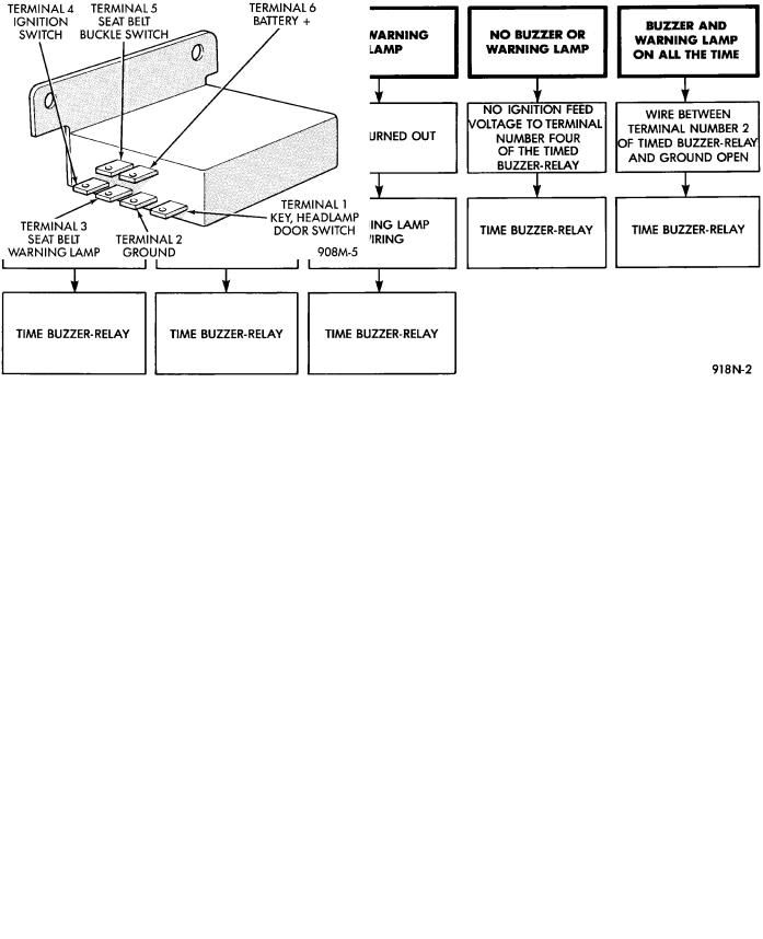
Fig. 1 Timed Buzzer-Relay Terminal Identification
TEST
(1)Connect 12 volt jumper wire to terminal number 4 of timed buzzer-relay, look at test lamp and listen for buzzer.
(2)Test lamp should come on and buzzer should sound for four to eight seconds and then both should go off; if not, replace timed buzzer-relay.
(3)If operation is okay, check all wiring in vehicle for opens, shorts, or poor connnections.
SEAT BELT BUCKLE SWITCH TEST BUZZER SYSTEM
Test timed buzzer-relay. If it checks OK, check the wiring between seat belt buckle and ground. The wire that goes to terminal 5 of relay from buckle
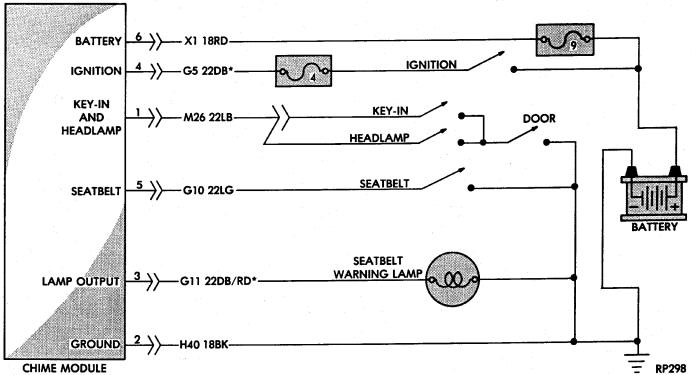
Fig. 2 Buzzer System Wiring Schematic
8U - 2 CHIME WARNING/REMINDER SYSTEM |
|
Ä |
|
Fig. 3 Seat Belt Warning System Diagnosis
switch, refer to Fig. 2 and 3. If they check out okay, replace buckle switch.
CHIME WARNING/REMINDER SYSTEM TEST
FASTEN SEAT BELTS
To test the fasten seat belts function, turn the ignition switch to the ON position with the driver's seat belt unbuckled. The seat belt warning lamp should light for four to eight seconds and the tone should sound three to five times.
HEADLAMPS LEFT ON
To test the headlamps left on function, turn headlamps on with drivers door open. Chime should sound until headlamps are turned off or drivers door is closed.
KEY LEFT IN IGNITION
To test the key left in ignition function, insert key into the ignition and open drivers door. Chime should sound until key is removed from ignition or drivers door is closed.
CHIME SYSTEM DIAGNOSISÐAA AND AP BODIES
WARNING: ON VEHICLES EQUIPPED WITH AN AIRBAG REFER TO THE AIR BAG PORTION OF THIS SECTION FOR STEERING WHEEL OR SWITCH REMOVAL AND INSTALLATION PROCEDURES.
CONDITION: NO TONE WHEN IGNITION SWITCH IS TURNED ON AND DRIVERS SEAT BELT OR AUTOMATIC SHOULDER HARNESS IS UNBUCKLED
PROCEDURE
(1)Check seat belt buckle switch (drivers seat) or rotary switch in automatic shoulder harness retractor for a ground when unbuckled.
(2)Check for battery feed at terminal 6 and ignition feed at terminal 4 of chime module (Fig. 4 and 5).
(3)Check for tone in any other function.
Fig. 4 Chime Module Terminal Identification
Ä |
|
CHIME WARNING/REMINDER SYSTEM 8U - 3 |
|
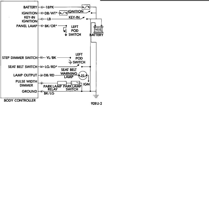
Fig. 5 Chime Module Wiring Ð AA and AP Bodies
CONDITION: NO FASTEN SEAT BELT LAMP WHEN IGNITION SWITCH IS TURNED ON.
CONDITION: NO TONE WHEN KEY IS LEFT IN IGNITION AND DRIVERS DOOR IS OPEN
PROCEDURE
(1)Check for burned out lamp.
(2)Check for battery feed at terminal 6 and lamp output at terminal 3 of chime module.
(3)Check for igniton feed at terminal 4 of chime module.
CONDITION: FASTEN SEAT BELT LAMP OR TONE CONTINUE FOR MORE THAN TEN SECONDS AFTER SEAT BELTS ARE FASTENED AND DRIVERS DOOR IS CLOSED
PROCEDURE
PROCEDURE
(1)Check left door jamb switch for good ground when drivers door is open.
(2)Check wiring connector for good contact at chime module.
(3)Check for battery feed at terminal 6 of chime module.
(4)Check key-in switch.
CONDITION: CHIMES CONTINUE WHEN HEADLAMPS ARE TURNED OFF AND/OR KEY IS REMOVED FROM IGNITION
(1)Check left door jamb switch.
(2)Check chime module.
CONDITION: NO TONE WHEN HEADLAMPS ARE ON AND DRIVERS DOOR IS OPEN
PROCEDURE
(1)Check wiring for a grounded condition between headlamp switch, key-in switch and chime module.
(2)Check chime module.
PROCEDURE
(1)Check left door jamb switch for good ground when drivers door is open.
(2)Check wiring connector for good contact at chime module.
(3)Check for battery feed at terminal 6 of chime module.
(4)Check headlamp switch.
CHIME SYSTEM DIAGNOSISÐAC, AG, AJ AND AY BODIES
CONDITION: NO TONE WHEN IGNITION IS TURNED ON AND DRIVER'S SEAT BELT IS UNBUCKLED
PROCEDURE
(1) Check driver's seat belt buckle switch for a ground when unbuckled.
8U - 4 CHIME WARNING/REMINDER SYSTEM
(2) Check for battery feed at terminal 16 and ignition feed at terminal 12 of 25-way body controller connector (Fig. 6, 7 and 8).
Fig. 6 Body Controller 25-Way Connector
Fig. 7 Chime System Wiring−AG and AJ Bodies
(3) Check for tone in any other function.
CONDITION: NO FASTEN SEAT BELT LAMP WHEN IGNITION SWITCH IS TURNED ON
PROCEDURE
(1)Check for burned out lamp.
(2)Check for battery feed at terminal 16 and lamp output at terminal 21 of 25-way body controller connector.
(3)Check for ignition feed at terminal 12 of 25-way body controller connector.
Ä
CONDITION: NO TONE WHEN HEADLAMPS ARE ON AND DRIVER'S DOOR IS OPEN, AND IGNITION IS OFF
PROCEDURE
(1)Check left door jamb switch for good ground when driver's door is open. This may be checked at terminal 1 of 25-way body controller connector.
(2)Check for battery feed at terminal 16 of 25-way body controller connector.
(3)Check headlamp switch.
CONDITION: NO TONE WHEN KEY IS LEFT IN IGNITION AND DRIVER'S DOOR IS OPEN
PROCEDURE
(1)Check left door jamb switch for good ground when driver's door is open. This may be checked at terminal 1 of 25-way body controller connector.
(2)Check for battery feed at terminal 16 of 25-way body controller connector.
(3)Check key-in switch.
CONDITION: CHIMES CONTINUE WHEN HEADLAMPS ARE TURNED OFF AND/OR KEY IS REMOVED FROM IGNITION
PROCEDURE
Check wiring for a grounded condition between headlamp switch, key-in switch, and body controller.
SERVICE PROCEDURES
CHIME MODULE REPLACEMENT AA and AP
BODIES
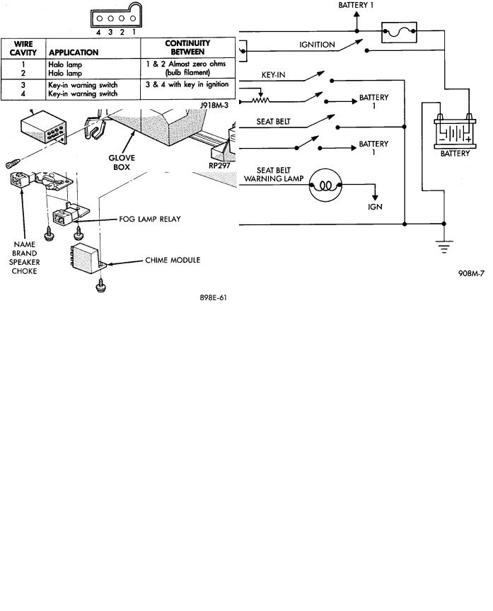
(1)Open glove box door and disconnect check strap.
(2)Disconnect glove box light switch.
(3)Remove screws from glove box assembly and remove.
(4)Remove two screws from chime module mounting bracket (Figs. 9 and 10).
(5)Disconnect chime module wiring and remove module.
(6)For installation reverse above procedures.
BODY CONTROLLER REPLACEMENT
Refer to Group 8E, Instrument Panel and Gauges.
SEAT BELT BUCKLE REPLACEMENT
Refer to Group 23, Body of this service manual.
HEADLAMP SWITCH REPLACEMENT
Refer to Group 8E, Instrument Panel and Gauges.
KEY-IN SWITCH REPLACEMENT
The Key-in switch is built into the ignition switch assembly. Should the Key-in switch require service, the ignition switch assembly must be replaced. Refer to Group 8D Ignition System of this service manual (Fig. 11).
Ä |
|
CHIME WARNING/REMINDER SYSTEM 8U - 5 |
|
Fig. 8 Chime System Wiring−AC and AY Bodies
Fig. 10 Chime Module Location
Fig. 9 Chime Module Location−AA Body
Fig. 11 Halo Lamp and Key-In Warning Switch
Continuity