

Ä |
FRAME AND BUMPERS |
13 - 1 |
|
FRAME AND BUMPERS |
|
|
CONTENTS |
|
|
page |
page |
BUMPER AND FASCIA . . . . . . |
. . . . . . . . . . . . . . 1 FRAME . . . . . . . . . . . . . . . . . . . . . . . . . . . . . |
. . . 9 |
|
BUMPER AND FASCIA |
|
|
INDEX |
|
|
page |
Front BumperÐAA-Vehicle . . . . . . . . . . . . . . . . . |
. . 1 |
Rear BumperÐAA-Vehicle . . . . . . . . . . . . . . . . . |
. . 5 |
Front BumperÐAC-Vehicle . . . . . . . . . . . . . . . . . |
. . 2 |
Rear BumperÐAC-Vehicle . . . . . . . . . . . . . . . . . |
. . 6 |
Front BumperÐAG-Vehicle . . . . . . . . . . . . . . . . . |
. . 3 |
Rear BumperÐAG-Vehicle . . . . . . . . . . . . . . . . . |
. . 7 |
Front BumperÐAJ-Vehicle . . . . . . . . . . . . . . . . . |
. . 4 |
SAFETY PRECAUTIONS AND WARNINGS
WARNING: BUMPER ENERGY ABSORBER UNITS CONTAIN PRESSURIZE GAS. DO NOT PUNCTURE OR HEAT ABSORBER UNIT FOR ANY REASON. PERSONAL INJURY CAN RESULT.
DO NOT VENTURE UNDER A HOISTED VEHICLE THAT IS NOT SUPPORTED ON SAFETY STANDS. PERSONAL INJURY CAN RESULT.
CAUTION: To avoid damaging a bright metal or painted finish bumper or fascia, use a padded work surface.
FRONT BUMPERÐAA-VEHICLE
BUMPER AND STANDARD FASCIA REMOVAL (FIG. 1)
(1)Remove socket and bulb from park and turn
lamp.
(2)Disconnect horn and fog lamp connectors (if equipped).
(3)Remove push-in fasteners holding sight shield to vertical support in front of radiator.
(4)Remove nuts holding fascia to fender, from behind forward flange of fender.
(5)Support front bumper assembly on suitable lifting device and remove bolts holding bumper reinforcement to energy absorber units.
|
page |
Rear BumperÐAJ-Vehicle . . . . . . . . . . . . . . . . . . |
. . 7 |
Front BumperÐAP-Vehicle . . . . . . . . . . . . . . . . . |
. . 4 |
Rear BumperÐAP-Vehicle . . . . . . . . . . . . . . . . . |
. . 8 |
Front BumperÐAY-Vehicle . . . . . . . . . . . . . . . . . |
. . 5 |
Rear BumperÐAY-Vehicle . . . . . . . . . . . . . . . . . |
. . 8 |
Safety Precautions and Warnings . . . . . . . . . . . . |
. . 1 |
INSTALLATION
Reverse the preceding operation. Align bumper height to approximately 3 mm (1/8 in.) gap to bottom of head lamp assemblies and flush to front fenders below the side marker lamps.
Fig. 1 Standard Front BumperÐAA-Vehicle
13 - 2 FRAME AND BUMPERS
BUMPER AND WRAP-AROUND FASCIA REMOVAL (FIG. 2)
(1)Remove socket and bulb from park and turn
lamp.
(2)Disconnect horn and fog lamp connectors (if equipped).
(3)Remove push-in plastic fasteners at forward edge of front wheel opening.
(4)Remove pal-nut fasteners from behind front fenders rearward of the side marker lamp.
(5)Remove push-in, fasteners holding sight shield to vertical support in front of radiator.
(6)Remove nuts holding fascia to fender, from behind forward flange of fender.
(7)Support front bumper on suitable lifting device and remove bolts holding bumper reinforcement to energy absorber units.
INSTALLATION
Reverse the preceding operation. Align bumper height to approximately 3 mm (1/8 in.) gap to bottom of head lamp assemblies and flush to front fenders below the side marker lamps.
Fig. 2 Wrap-around Front BumperÐAA-Vehicle
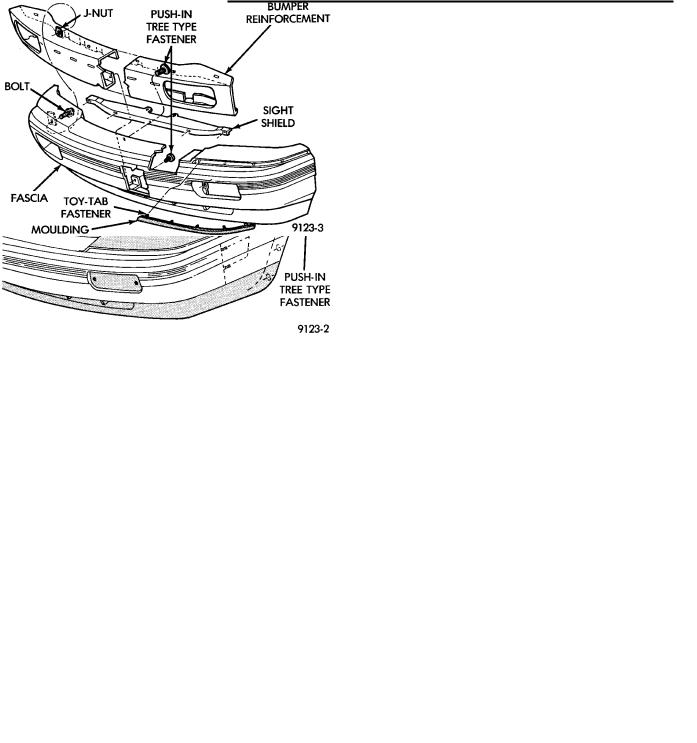
BUMPER OVERHAUL (FIG. 3)
(1)Position bumper assembly on a suitable padded work surface to avoid damage to painted fascia.
(2)Remove sight shield push-in, fasteners and separate shield from assembly.
(3)Remove air dam screws and push-in fasteners and lift dam out of retaining channels at ends of fas-
Ä
cia. Remove dam retaining channels and reinforcements from fascia (if equipped).
(4)Remove park and turn signal lamp assemblies, see Group 8L, Lamps
(5)Remove fog lamp bracket from bottom of bumper reinforcement (if equipped).
(6)Remove horns from back of bumper reinforce-
ment.
(7)Remove lower air intake louver screws and push-in fastener and separate louver from fascia.
(8)Remove upper reinforcement to fascia attaching bolts and separate reinforcement from fascia.
(9)Straighten toy-tab fasteners holding horizontal moulding to fascia and separate moulding from two sided adhesive tape behind moulding. Remove moulding from fascia.
To assemble, reverse the preceding operation.
Fig. 3 Front Bumper OverhaulÐAA-Vehicle
FRONT BUMPERÐAC VEHICLE
FRONT BUMPER AND STANDARD FASCIA REMOVALÐAC/D OR AC/C-H-BODY (FIG. 4)
(1)Remove nuts holding fascia to fender, from behind forward flange of fender.
(2)Support front bumper assembly on suitable lifting device and remove bolts holding bumper reinforcement to energy absorber units.
(3)Separate bumper from vehicle.
INSTALLATION
Reverse the preceding operation. Align bumper height to fit flush to bottom of head lamp assemblies and grille.
FRONT BUMPER OVERHAULÐAC\ OR AC/C-H- BODYÐ(FIG. 4)
(1) Position bumper assembly on a suitable padded
Ä |
|
FRAME AND BUMPERS 13 - 3 |
|
Fig. 4 Front BumperÐAC\ or AC/C-H-Body
work surface to avoid damage to painted fascia.
(2)Remove push-in fasteners holding fascia to reinforcement.
(3)Remove upper reinforcement to fascia attaching bolts and separate reinforcement from fascia.
To assemble, reverse the preceding operation.
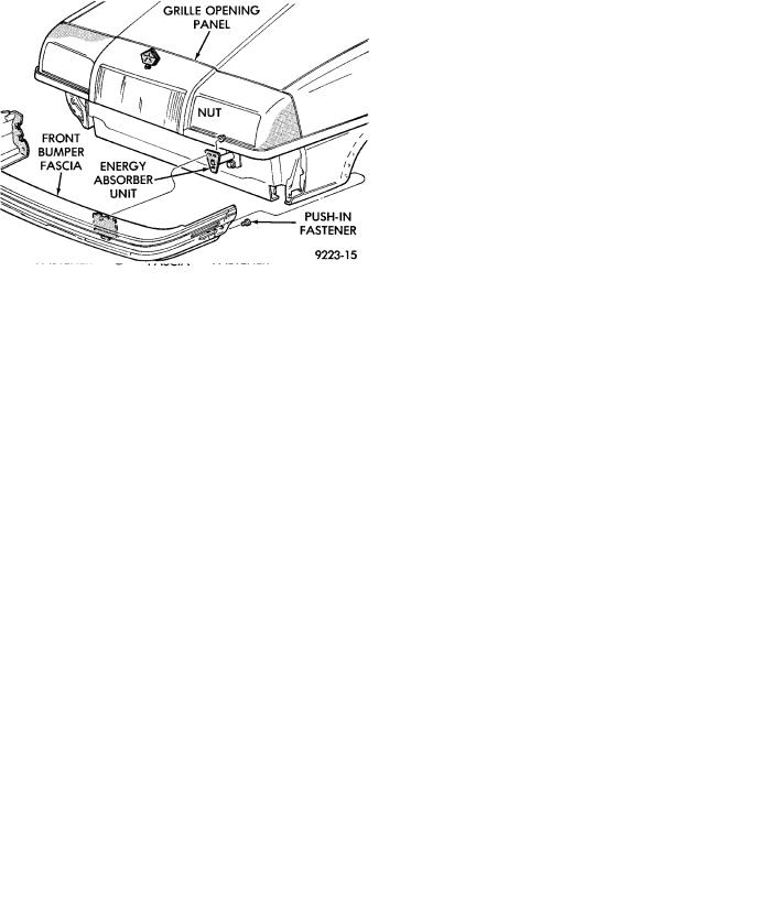
FRONT BUMPER AND FASCIA REMOVALÐ AC/C-BODY (FIG. 5)
(1)Raise vehicle and support on safety stands.
(2)Remove push-in fasteners holding bumper fascia to front wheel opening lip.
(3)Support bumper on a suitable lifting device.
(4)Remove nuts holding bumper reinforcement to energy absorbers.
(5)Separate bumper from vehicle.
INSTALLATION
Reverse the preceding operation.
BUMPER OVERHAULÐAC/C-BODY
(1)Position bumper assembly on a suitable padded work surface to avoid damage to painted fascia.
(2)Remove bolts holding bumper face bar to reinforcement.
(3)Remove push-in fasteners holding fascia to reinforcement.
(4)Separate reinforcement from fascia.
To assemble, reverse the preceding operation.
FRONT BUMPERÐAG-VEHICLE
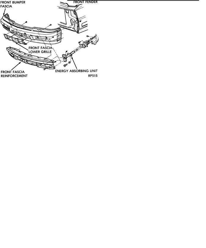
FRONT BUMPER FASCIA REMOVAL (FIG. 6)
(1)Remove headlamp and fog lamp (if equipped) assemblies, refer to Group 8L, Lamps.
(2)Raise vehicle and support on safety stands.
(3)Remove radiator closure panel sight shield.
(4)Remove push-in fasteners holding fascia to front fender wheel opening flange.
(5)Remove nuts holding fascia to fender from above side marker reflectors. Remove fender splash shields if necessary.
(6)Remove nuts holding front fascia headlamp mounting panel to forward edge of fenders.
(7)Remove bolts holding fascia headlamp mounting panel to radiator closure panel brace.
(8)Remove push-in fasteners holding fascia to bottom of bumper reinforcement.
(9)Separate front bumper fascia and headlamp mounting panel from vehicle.
INSTALLATION
Reverse the preceding operation. If headlamps require aiming, refer to Group 8L, Lamps.
Fig. 6 Front Bumper FasciaÐAG-Vehicle
Fig. 5 Front BumperÐAC/C-Body
13 - 4 FRAME AND BUMPERS
HEADLAMP MOUNTING PANEL
REMOVALÐAG-VEHICLE (FIG. 7)
(1)Remove all lamp assemblies, refer to group 8L, Lamps.
(2)Remove front bumper fascia.
(3)Remove bolts holding fascia to headlamp mounting panel ends.
(4)Remove push-in fasteners holding fascia to headlamp mounting panel.
(5)Separate headlamp mounting panel from fascia.
INSTALLATION
Reverse the preceding operation
Fig. 7 Headlamp Mounting PanelÐAG-Vehicle
FRONT BUMPER REINFORCEMENT REMOVALÐAG-VEHICLE (FIG. 8)
(1)Remove bumper fascia as necessary to gain clearance to remove bumper reinforcement.
(2)Remove nuts holding bumper reinforcement to energy absorber units.
(3)Separate bumper reinforcement from vehicle. carriage
INSTALLATION
Reverse the preceding operation
FRONT BUMPER ENERGY ABSORBER REMOVALÐAG-VEHICLE (FIG. 8)
(1)Remove front fascia and bumper reinforcement as necessary to remove absorber unit.
(2)Remove bolts holding energy absorber unit to front closure panel.
(3)Separate energy absorber from vehicle.
INSTALLATION
Reverse the preceding operation.
Ä
Fig. 8 Front Bumper Reinforcement and Energy
Absorber UnitÐAG-Vehicle
FRONT BUMPERÐAJ-VEHICLE
REMOVAL (FIG. 9)
(1)Remove socket and bulb from park and turn
lamp.
(2)Remove nuts holding fascia to fender, from behind forward flange of fender.
(3)Support front bumper assembly on suitable lifting device and remove bolts holding bumper reinforcement to energy absorber units.
INSTALLATION
Reverse the preceding operation. Align bumper height to approximately 5 mm (0.200 in.) gap to bottom of grille and flush to front fenders on the sides.
Fig. 9 Front Bumper and FasciaÐAJ-Vehicle
FRONT BUMPERÐAP-VEHICLE
REMOVAL (FIG. 10)
(1) Raise vehicle and support on safety stands.