

Ä |
|
IGNITION SYSTEMS 8D - 1 |
|
IGNITION SYSTEMS
CONTENTS
|
page |
|
|
|
page |
2.2L TBI, 2.5L TBI, TURBO I AND 3.0L |
|
IGNITION SWITCH . . . . . |
. . . . . . . . . . . . . . . . |
. 48 |
|
IGNITION SYSTEMSÐDIAGNOSTIC |
|
SPECIFICATIONS |
. . . . . . |
. . . . . . . . . . . . . . . . |
. 50 |
PROCEDURES . . . . . . . . . . . . . . . . . . . . . . . |
. 11 |
TURBO III, 3.3L |
AND 3.8L IGNITION SYSTEM |
|
|
2.2L TBI, 2.5L TBI, TURBO I AND 3.0L |
|
ÐDIAGNOSTIC PROCEDURES . . . . . . . . . . |
. 37 |
||
IGNITION SYSTEMSÐSERVICE |
|
TURBO III, 3.3L |
AND 3.8L |
IGNITION SYSTEM |
|
PROCEDURES . . . . . . . . . . . . . . . . . . . . . . . |
. 14 |
ÐSYSTEM OPERATION |
. . . . . . . . . . . . . . . . |
. 26 |
|
2.2L TBI, 2.5L TBI, TURBO I AND 3.0L |
|
TURBO III, 3.3L |
AND 3.8L |
IGNITION |
|
IGNITION SYSTEMSÐSYSTEM OPERATION |
. 1 |
SYSTEMSÐSERVICE PROCEDURES . . . . . |
. 41 |
||
GENERAL INFORMATION
Throughout this group, references are made to particular vehicles by letter designation. A chart explaining the designations appears in the Introduction Section of this manual.
2.2L TBI, 2.5L TBI, TURBO I AND 3.0L IGNITION SYSTEMSÐ
SYSTEM OPERATION
INDEX
|
page |
|
page |
Auto Shutdown (ASD) Relay and Fuel Pump |
|
Distributor Pick-UpÐ3.0L Engine . . . . . . . . . . . . |
. . 7 |
Relay . . . . . . . . . . . . . . . . . . . . . . . . . . . . . . . |
. . 9 |
Engine Controller . . . . . . . . . . . . . . . . . . . . . . . . |
. . 6 |
Coolant Temperature Sensor . . . . . . . . . . . . . . . |
. . 7 |
General Information . . . . . . . . . . . . . . . . . . . . . . |
. . 1 |
Detonation Sensor (Knock Sensor)ÐTurbo I |
|
Ignition Coil . . . . . . . . . . . . . . . . . . . . . . . . . . . . |
. . 9 |
Engine . . . . . . . . . . . . . . . . . . . . . . . . . . . . . . |
. . 8 |
Manifold Absolute Pressure (MAP) Sensor . . . . . |
. . 8 |
Distributor (Hall Effect) Pick-UpÐEngine Controller |
|
Rotor . . . . . . . . . . . . . . . . . . . . . . . . . . . . . . . . . |
. . 2 |
Input . . . . . . . . . . . . . . . . . . . . . . . . . . . . . . . |
. . 6 |
Spark Plug Cables . . . . . . . . . . . . . . . . . . . . . . . |
. . 2 |
Distributor Cap . . . . . . . . . . . . . . . . . . . . . . . . . . |
. . 1 |
Spark Plugs . . . . . . . . . . . . . . . . . . . . . . . . . . . . |
. . 3 |
GENERAL INFORMATION
This section describes the ignition systems of the 2.2L TBI, 2.5L TBI, Turbo I and 3.0L engines.
The Fuel Injection sections of Group 14 explain On Board Diagnostics.
Group 0, Lubrication and Maintenance, contains general maintenance information for ignition related items. The Owner's Manual also contains maintenance information.
DISTRIBUTOR CAP
Remove the distributor cap and inspect the inside for flashover, cracking of carbon button, lack of spring tension on carbon button, cracking of cap, and burned, worn terminals (Fig. 1). Also check for broken distributor cap towers. If any of these conditions are present the distributor cap and/or cables should be replaced.
When replacing the distributor cap, transfer cables from the original cap to the new cap one at a time.
Fig. 1 Distributor Cap Inspection
Ensure each cable is installed into the corresponding tower of the new cap. Fully seat the wires into the towers. If necessary, refer to the appropriate engine
8D - 2 IGNITION SYSTEMS |
|
Ä |
|
firing order diagram (Fig. 2 or Fig. 3).
Light scaling of the terminals can be cleaned with a sharp knife. If the terminals are heavily scaled, replace the distributor cap.
A cap that is greasy, dirty or has a powder-like substance on the inside should be cleaned with a solution of warm water and a mild detergent. Scrub the cap with a soft brush. Thoroughly rinse the cap and dry it with a clean soft cloth.
|
Fig. 4 Rotor InspectionÐTypical |
|
The nipples and spark plug covers should be in good |
Fig. 2 Engine Firing OrderÐ2.2L TBI, 2.5L TBI, |
condition. Nipples should fit tightly on the coil and |
Turbo I and Turbo III Engines |
distributor cap towers and spark plug cover should fit |
|
tight around spark plug insulators. Loose cable con- |
|
nections can cause ignition malfunctions by permit- |
|
ting water to enter the towers, corroding, and increas- |
|
ing resistance. To maintain proper sealing at the |
|
terminal connections, the connections should |
|
not be broken unless testing indicates high re- |
|
sistance, an open circuit or other damage. |
|
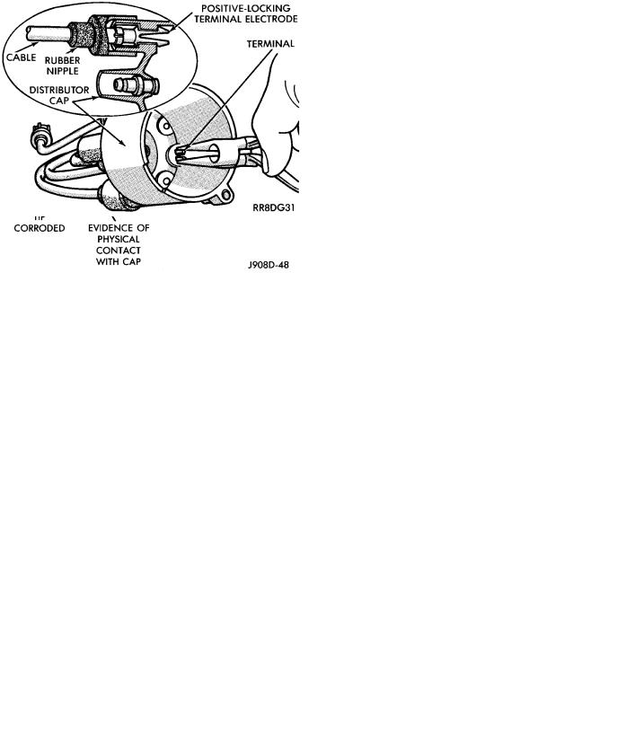
CAUTION: Do not pull spark plug cables from dis- |
|
tributor cap of four cylinder engines. The cables |
|
must be released from inside the distributor cap |
|
(Fig. 5). |
Fig. 3 Engine Firing OrderÐ3.0L Engine
ROTOR
Replace the rotor if it is cracked, the tip is excessively burned or heavily scaled (Fig. 4). If the spring terminal does not have adequate tension, replace the rotor.
SPARK PLUG CABLES
Spark Plug cables are sometimes referred to as secondary ignition wires. They transfer electrical current from the distributor to individual spark plugs at each cylinder. 2.2L TBI, 2.5L TBI, Turbo I , Turbo III and 3.0L engines use resistance type cables. The cables suppress radio frequency emissions from the ignition system.
Check the spark plug cable connections for good contact at the coil and distributor cap towers and at the spark plugs. Terminals should be fully seated.
Fig. 5 Spark Plug Cable Removal/InstallationÐ2.2L
and 2.5L TBI Engines