

G1000TM
Pilot’s Guide for Cessna Nav III

|
|
Part Number |
|
Change Summary |
|
|
|
|
190-00498-00 |
Initial release. |
|
|
|
|
|
(Rev.A) |
|
|
|
|
|
|
|
|
|
|
|
|
|
|
|
|
|
|
|
|
|
|
Record of Revisions |
|
|
Revision |
Date of Revision |
Revision Page Range |
Description |
|
||
A |
11/05 |
|
i through I-8 |
Initial release. |
|
|
|
|
|
|
|
|
|
Garmin G1000 Pilot’s Guide for Cessna Nav III |
190-00498-00 Rev.A |

COPYRIGHT
Copyright © 2005 Garmin Ltd. or its subsidiaries. All rights reserved.
This manual reflects the operation of System Software versions 0394.06 or later for Cessna 172R aircraft,0395.07 or later for Cessna 172S aircraft, 0371.15 or later for normally aspirated Cessna 182 aircraft, 0372.14 or later for turbocharged Cessna 182 aircraft, 0373.10 or later for normally aspirated Cessna 206 aircraft, and 0374.10 or later for turbocharged Cessna 206 aircraft. Some differences in operation may be observed when comparing the information in this manual to earlier or later software versions.
NOTE: Cessna Nav III aircraft include the Cessna 172R, the Cessna 172S, the normally aspirated Cessna 182 (182), the turbocharged Cessna 182 (T182), the normally aspirated Cessna 206 (206), and the turbocharged Cessna 206 (T206). Unless otherwise indicated, information in the G1000 Pilot’s Guide binder pertains to all Cessna Nav III aircraft.
Garmin International, Inc., 1200 East 151st Street, Olathe, Kansas 66062, U.S.A.
Tel: 913/397.8200 |
Fax: 913/397.8282 |
Garmin AT, Inc., 2345 Turner Road SE, Salem, OR 97302, U.S.A. |
|
Tel: 503/391.3411 |
Fax 503/364.2138 |
Garmin (Europe) Ltd., Unit 5,The Quadrangle,Abbey Park Industrial Estate, Romsey, Hampshire S051 9DL, U.K. |
|
Tel: 44/0870.8501241 |
Fax: 44/0870.8501251 |
Garmin Corporation, No. 68, Jangshu 2nd Road, Shijr,Taipei County,Taiwan |
|
Tel: 886/02.2642.9199 |
Fax: 886/02.2642.9099 |
Web Site Address: www.garmin.com
Except as expressly provided herein, no part of this manual may be reproduced, copied, transmitted, disseminated, downloaded or stored in any storage medium, for any purpose without the express written permission of Garmin. Garmin hereby grants permission to download a single copy of this manual and of any revision to this manual onto a hard drive or other electronic storage medium to be viewed for personal use, provided that such electronic or printed copy of this manual or revision must contain the complete text of this copyright notice and provided further that any unauthorized commercial distribution of this manual or any revision hereto is strictly prohibited.
Garmin® is a registered trademark of Garmin Ltd. or its subsidiaries, and G1000™ is a trademark of Garmin Ltd. or its subsidiaries. These trademarks may not be used without the express permission of Garmin.
Bendix/King® and Honeywell® are registered trademarks of Honeywell International, Inc., Silver Crown Plus™ is a trademark of Honeywell International, Inc.; NavData® is a registered trademark of Jeppesen, Inc.; Stormscope® and Skywatch® are registered trademarks of L-3 Communications;TCAD® is a registered trademark of Ryan International, Inc.; and XM® is a registered trademark of XM Satellite Radio, Inc.
November 2005 |
190-00498-00 Rev.A |
Printed in the U.S.A. |
190-00498-00 Rev.A |
Garmin G1000 Pilot’s Guide for Cessna Nav III |
i |

WARNINGS & CAUTIONS
WARNING: Navigation and terrain separation must NOT be predicated upon the use of the terrain function. The G1000 Terrain Proximity feature is NOT intended to be used as a primary reference for terrain avoidance and does not relieve the pilot from the responsibility of being aware of surroundings during flight. The Terrain Proximity feature is only to be used as an aid for terrain avoidance and is not certified for use in applications requiring a certified terrain awareness system. Terrain data is obtained from third party sources. Garmin is not able to independently verify the accuracy of the terrain data.
WARNING: The displayed minimum safe altitudes (MSAs) are only advisory in nature and should not be relied upon as the sole source of obstacle and terrain avoidance information. Always refer to current aeronautical charts for appropriate minimum clearance altitudes.
WARNING:The Garmin G1000,as installed in Cessna Nav III aircraft,has a very high degree of functional integrity. However, the pilot must recognize that providing monitoring and/or self-test capability for all conceivable system failures is not practical. Although unlikely, it may be possible for erroneous operation to occur without a fault indication shown by the G1000. It is thus the responsibility of the pilot to detect such an occurrence by means of cross-checking with all redundant or correlated information available in the cockpit.
 WARNING: For safety reasons, G1000 operational procedures must be learned on the ground.
WARNING: The altitude calculated by G1000 GPS receivers is geometric height above Mean Sea Level and could vary significantly from the altitude displayed by pressure altimeters, such as the GDC 74A Air Data Computer, or other altimeters in aircraft. GPS altitude should never be used for vertical navigation. Always use pressure altitude displayed by the G1000 PFD or other pressure altimeters in aircraft.
WARNING: The Jeppesen database used in the G1000 system must be updated regularly in order to ensurethatitsinformationremainscurrent. Updatesarereleasedevery28days. Adatabaseinformation packet is included in the G1000 package. Pilots using an outdated database do so entirely at their own risk.
ii |
Garmin G1000 Pilot’s Guide for Cessna Nav III |
190-00498-00 Rev.A |

WARNINGS & CAUTIONS
WARNING: The basemap (land and water data) must not be used for navigation,but rather only for nonnavigational situational awareness. Any basemap indication should be compared with other navigation sources.
CAUTION:The illustrations in this guide are only examples. Never use the G1000 to attempt to penetrate a thunderstorm. Both the FAA Advisory Circular, Subject:Thunderstorms, and the Airman’s Information Manual (AIM) recommend avoiding “by at least 20 miles any thunderstorm identified as severe or giving an intense radar echo.”
CAUTION:TheUnitedStatesgovernmentoperatestheGlobalPositioningSystemandissolelyresponsible for its accuracy and maintenance. The GPS system is subject to changes which could affect the accuracy and performance of all GPS equipment. Portions of the Garmin G1000 utilize GPS as a precision electronic NAVigation AID (NAVAID). Therefore, as with all NAVAIDs, information presented by the G1000 can be misused or misinterpreted and, therefore, become unsafe.
CAUTION: To reduce the risk of unsafe operation, carefully review and understand all aspects of the G1000 Pilot’s Guide documentation. Thoroughly practice basic operation prior to actual use. During flight operations, carefully compare indications from the G1000 to all available navigation sources, including the information from other NAVAIDs, visual sightings, charts, etc. For safety purposes, always resolve any discrepancies before continuing navigation.
CAUTION: The Garmin G1000 does not contain any user-serviceable parts. Repairs should only be made by an authorized Garmin service center. Unauthorized repairs or modifications could void both the warranty and the pilot’s authority to operate this device under FAA/FCC regulations.
CAUTION: The GDU 1040 PFD and MFD displays use a lens coated with a special anti-reflective coating that is very sensitive to skin oils, waxes, and abrasive cleaners. CLEANERS CONTAINING AMMONIA WILL HARM THE ANTI-REFLECTIVE COATING. It is very important to clean the lens using a clean, lintfree cloth and an eyeglass lens cleaner that is specified as safe for anti-reflective coatings.
190-00498-00 Rev.A |
Garmin G1000 Pilot’s Guide for Cessna Nav III |
iii |

WARNINGS & CAUTIONS
 NOTE: All visual depictions contained within this document,including screen images of the G1000 panel and displays, are subject to change and may not reflect the most current G1000 system. Depictions of equipment may differ slightly from the actual equipment.
 NOTE: This device complies with part 15 of the FCC Rules. Operation is subject to the following two conditions: (1) this device may not cause harmful interference, and (2) this device must accept any interference received, including interference that may cause undesired operation.
 NOTE: There are several atmospheric phenomena in addition to nearby thunderstorms that can cause isolated discharge points in the strike display mode. However, clusters of two or more discharge points in the strike display mode do indicate thunderstorm activity if these points reappear after the screen has been cleared. Avoid the clusters to avoid the thunderstorms. In the cell display mode, even a single discharge point may represent thunderstorm activity and should therefore be avoided.
iv |
Garmin G1000 Pilot’s Guide for Cessna Nav III |
190-00498-00 Rev.A |

WARRANTY
LIMITED WARRANTY
This Garmin product is warranted to be free from defects in materials or workmanship for two years from the date of purchase. Within this period, Garmin will, at its sole option, repair or replace any components that fail in normal use. Such repairs or replacement will be made at no charge to the customer for parts and labor, provided that the customer shall be responsible for any transportation cost. This warranty does not cover failures due to abuse, misuse, accident, or unauthorized alterations or repairs.
THEWARRANTIESAND REMEDIES CONTAINED HEREINARE EXCLUSIVEAND IN LIEU OFALL OTHERWARRANTIES EXPRESS OR IMPLIED OR STATUTORY, INCLUDING ANY LIABILITY ARISING UNDER ANY WARRANTY OF MERCHANTABILITY OR FITNESS FOR A PARTICULAR PURPOSE, STATUTORY OR OTHERWISE. THIS WARRANTY GIVES YOU SPECIFIC LEGAL RIGHTS,WHICH MAY VARY FROM STATE TO STATE.
IN NO EVENT SHALL GARMIN BE LIABLE FOR ANY INCIDENTAL, SPECIAL, INDIRECT OR CONSEQUENTIAL DAMAGES,WHETHER RESULTING FROM THE USE, MISUSE, OR INABILITY TO USE THIS PRODUCT OR FROM DEFECTS IN THE PRODUCT. Some states do not allow the exclusion of incidental or consequential damages, so the above limitations may not apply to you.
Garmin retains the exclusive right to repair or replace the unit or software, or to offer a full refund of the purchase price, at its sole discretion. SUCH REMEDY SHALL BE YOUR SOLE AND EXCLUSIVE REMEDY FOR ANY BREACH OF WARRANTY.
To obtain warranty service, contact your local GarminAuthorized Service Center. For assistance in locating a Service Center near you, visit the Garmin Web site at “http://www.garmin.com” or contact Garmin Customer Service at 800-800-1020.
190-00498-00 Rev.A |
Garmin G1000 Pilot’s Guide for Cessna Nav III |
v |

WARRANTY
This page intentionally left blank.
vi |
Garmin G1000 Pilot’s Guide for Cessna Nav III |
190-00498-00 Rev.A |

|
SECTION 1 SYSTEM OVERVIEW |
|
|
|
|
1.1 |
System Description......................................... |
1-1 |
1.2 |
Line Replaceable Units................................... |
1-1 |
1.3 |
PFD/MFD Controls .......................................... |
1-7 |
1.4 |
Secure Digital Cards....................................... |
1-9 |
1.5 |
System Power-up........................................... |
1-10 |
1.6 |
Display Backlighting...................................... |
1-12 |
1.7 |
System Operation.......................................... |
1-12 |
|
Normal Mode........................................................... |
1-12 |
|
Reversionary Mode .................................................. |
1-13 |
|
AHRS Operation....................................................... |
1-14 |
|
|
|
|
SECTION 2 PRIMARY FLIGHT DISPLAY |
|
|
|
|
2.1 |
Introduction.................................................... |
2-1 |
2.2 |
Backlighting ................................................... |
2-4 |
2.3 |
Softkey Function ............................................ |
2-5 |
2.4 |
Flight Instruments.......................................... |
2-9 |
|
Airspeed Indicator...................................................... |
2-9 |
|
Attitude Indicator..................................................... |
2-10 |
|
Altimeter.................................................................. |
2-12 |
|
Vertical Speed Indicator ........................................... |
2-14 |
|
Horizontal Situation Indicator .................................. |
2-15 |
2.5 |
Communication, Navigation & Surveillance.. |
2-21 |
|
Communication FrequencyWindow......................... |
2-21 |
|
Navigation FrequencyWindow................................. |
2-21 |
|
Navigation Status Bar .............................................. |
2-22 |
|
Transponder Status Bar ............................................ |
2-23 |
2.6 |
Supplemental Flight Data.............................. |
2-24 |
|
OutsideAirTemperature Box.................................... |
2-24 |
|
SystemTime Box ...................................................... |
2-24 |
|
TrafficAnnunciation ................................................. |
2-24 |
|
Terrain Proximity...................................................... |
2-25 |
|
TerrainAwareness andWarning System (TAWS) |
|
|
(Optional)................................................................. |
2-26 |
|
TABLE OF CONTENTS |
||
|
|
|
|
Inset Map................................................................. |
2-27 |
|
|
Working with Menus................................................ |
2-29 |
|
|
AuxiliaryWindow Keys............................................. |
2-30 |
|
|
AuxiliaryWindows.................................................... |
2-31 |
|
|
2.7 Reversionary Mode ....................................... |
2-45 |
|
|
2.8 Alerts and Annunciations............................... |
2-46 |
|
|
AlertsWindow.......................................................... |
2-46 |
|
|
AnnunciationWindow.............................................. |
2-46 |
|
|
SoftkeyAnnunciations.............................................. |
2-46 |
|
|
|
|
|
|
SECTION 3 NAV/COM |
|
|
|
|
|
|
|
3.1 Overview ........................................................ |
3-1 |
|
|
Windows and Fields ................................................... |
3-2 |
|
|
Radio Selection........................................................... |
3-2 |
|
|
Controls...................................................................... |
3-3 |
|
|
Tuning Box ................................................................. |
3-4 |
|
|
Switching Between Radios......................................... |
3-4 |
|
|
ManuallyTuning a Frequency..................................... |
3-4 |
|
|
Radio Indicators......................................................... |
3-5 |
|
|
Volume....................................................................... |
3-5 |
|
|
FrequencyTransferArrow........................................... |
3-5 |
|
|
3.2 COM Operation............................................... |
3-6 |
|
|
Frequency Spacing...................................................... |
3-6 |
|
|
Automatic Squelch..................................................... |
3-6 |
|
|
Selecting a COM Radio............................................... |
3-6 |
|
|
Emergency Frequency (121.500 MHz)........................ |
3-7 |
|
|
Quick-Tuning andActivating 121.500 MHz................ |
3-7 |
|
|
Stuck Microphone ...................................................... |
3-7 |
|
|
3.3 NAV Operation................................................ |
3-8 |
|
|
Frequency Range........................................................ |
3-8 |
|
|
Morse Code Identifier................................................. |
3-8 |
|
|
NAV Radio Selection for Navigation........................... |
3-8 |
|
|
ADF/DMETuning ........................................................ |
3-9 |
|
|
DMETuning................................................................ |
3-9 |
|
|
3.4 Frequency Auto-tuning.................................. |
3-10 |
|
|
Auto-tuning on the PFD ........................................... |
3-10 |
|
|
190-00498-00 Rev.A |
Garmin G1000 Pilot’s Guide for Cessna Nav III |
vii |

TABLE OF CONTENTS
Auto-tuning on the MFD.......................................... |
3-11 |
Auto-Tuning onApproachActivation |
|
(NAV Frequencies).................................................... |
3-17 |
|
SECTION 4 TRANSPONDER |
|
|
|
|
4.1 Transponder Description................................. |
4-1 |
|
|
Transponder Softkeys ................................................. |
4-1 |
|
Transponder Status Bar .............................................. |
4-1 |
|
Mode S Features......................................................... |
4-2 |
|
Traffic Information Service (TIS).................................. |
4-2 |
4.2 |
Operation ....................................................... |
4-3 |
|
Mode Selection .......................................................... |
4-3 |
|
Code Selection ........................................................... |
4-4 |
|
IDENT Function .......................................................... |
4-5 |
|
|
|
|
SECTION 5 AUDIO PANEL |
|
|
|
|
5.1 Audio Panel Description................................. |
5-1 |
|
|
Transceivers................................................................ |
5-1 |
|
Mono/Stereo Headsets............................................... |
5-2 |
|
Unmuted/Unswitched Inputs...................................... |
5-2 |
|
Front Panel Controls................................................... |
5-2 |
5.2 |
Operation ....................................................... |
5-4 |
|
Power-up and Fail-safe Operation.............................. |
5-4 |
|
KeyAnnunciators........................................................ |
5-4 |
|
Lighting...................................................................... |
5-4 |
|
Transceiver Keys......................................................... |
5-4 |
|
Optional COM Muting................................................ |
5-5 |
|
Split COM Function.................................................... |
5-5 |
|
PA Function................................................................ |
5-5 |
|
Speaker ...................................................................... |
5-6 |
|
Marker Beacon Receiver............................................. |
5-6 |
|
Marker BeaconVolumeAdjustment ........................... |
5-6 |
|
Navigation Radios...................................................... |
5-7 |
|
Intercom System (ICS) Isolation.................................. |
5-8 |
|
IntercomVolume and Squelch.................................... |
5-9 |
|
Entertainment Inputs.................................................. |
5-9 |
|
GDL 69/69A XM Radio System................................. |
5-10 |
|
MasterAvionics Squelch (MASQ)............................. |
5-10 |
|
Digital Clearance Recorder with Playback Capability5-11 |
|
|
Reversionary Mode .................................................. |
5-11 |
|
|
|
|
SECTION 6 ENGINE INDICATION SYSTEM |
|
|
|
|
6.1 |
Introduction.................................................... |
6-1 |
|
EIS Pages.................................................................... |
6-1 |
|
EIS Indicators.............................................................. |
6-1 |
|
EiS Page Reversion..................................................... |
6-2 |
6.2 |
Engine Page.................................................... |
6-3 |
6.3 |
Lean Page....................................................... |
6-6 |
6.4 |
System Page ................................................... |
6-9 |
|
|
|
|
SECTION 7 MULTI FUNCTION DISPLAY |
|
|
|
|
7.1 |
Introduction.................................................... |
7-1 |
|
Description................................................................. |
7-1 |
|
Reversionary Mode .................................................... |
7-1 |
|
Optional Equipment................................................... |
7-1 |
|
MFD Power-up............................................................ |
7-2 |
|
MFD Backlighting....................................................... |
7-2 |
|
MFD Softkeys ............................................................ |
7-2 |
|
Electronic Checklists (optional) .................................. |
7-4 |
|
MFD Page Groups ...................................................... |
7-7 |
|
WorkingWith Menus.................................................. |
7-8 |
7.2 |
Navigation Map Page..................................... |
7-9 |
|
Navigation Map Page Operations ............................ |
7-11 |
7.3 |
Traffic Map Page............................................ |
7-33 |
|
TIS Symbology.......................................................... |
7-34 |
|
Traffic Map Page Operations.................................... |
7-34 |
7.4 |
Terrain Proximity Page .................................. |
7-37 |
|
Terrain Proximity Page Operations ........................... |
7-38 |
|
Displaying Obstacle Data ......................................... |
7-39 |
|
Navigation Map Display Conditions......................... |
7-39 |
viii |
Garmin G1000 Pilot’s Guide for Cessna Nav III |
190-00498-00 Rev.A |
7.5 Terrain Awareness & Warning System |
|
|
|
(TAWs) Display (Optional)............................ |
7-40 |
|
DisplayingTerrain on theTAWS Page ....................... |
7-40 |
7.6 |
Direct-to Navigation...................................... |
7-49 |
|
Direct-to Navigation Operations............................... |
7-50 |
7.7 |
Flight Plans.................................................... |
7-54 |
|
Active Flight Plan Page............................................. |
7-54 |
|
Active Flight Plan Page Options ............................... |
7-54 |
|
Flight Plan Catalog Page.......................................... |
7-64 |
|
Flight Plan Catalog Page Operations ....................... |
7-64 |
|
Vertical Navigation (VNAV) Page.............................. |
7-70 |
7.8 |
Procedures..................................................... |
7-72 |
|
Arrivals and Departures............................................ |
7-72 |
|
Approaches.............................................................. |
7-73 |
|
G1000 Navigational Guidance forApproaches ........ |
7-73 |
|
SelectingApproaches............................................... |
7-74 |
7.9 Waypoint Page Group.................................... |
7-77 |
|
|
AIRPORT Information Page (INFO)............................ |
7-78 |
|
Airport Frequency Information Field......................... |
7-81 |
|
AIRPORT Information Page Options ......................... |
7-82 |
|
Departure Information Page (DP)............................. |
7-83 |
|
Arrival Information Page (STAR)............................... |
7-84 |
|
Approach Information Page...................................... |
7-86 |
|
Intersection Information Page.................................. |
7-88 |
|
NDB Information Page.............................................. |
7-90 |
|
VOR Information Page.............................................. |
7-93 |
|
UserWaypoint Information Page.............................. |
7-96 |
|
Creating UserWaypoints.......................................... |
7-98 |
|
Modifying UserWaypoints ..................................... |
7-100 |
|
UserWaypoint Information Page Options............... |
7-101 |
7.10 Auxiliary Page Group................................. |
7-105 |
|
|
Trip Planning Page.................................................. |
7-105 |
|
GPS Status Page..................................................... |
7-112 |
|
System Setup Page................................................. |
7-116 |
|
System Status Page................................................ |
7-124 |
|
|
TABLE OF CONTENTS |
||
|
|
|
|
|
7.11 Nearest Page Group .................................. |
7-125 |
|
||
|
Navigating to a NearestWaypoint ......................... |
7-126 |
|
|
|
Nearest Intersections Page..................................... |
7-130 |
|
|
|
Nearest NDB Page.................................................. |
7-131 |
|
|
|
NearestVOR Page .................................................. |
7-132 |
|
|
|
Nearest UserWaypoint Page.................................. |
7-134 |
|
|
|
Nearest Frequencies Page....................................... |
7-135 |
|
|
|
NearestAirspaces Page.......................................... |
7-137 |
|
|
|
|
|
|
|
|
SECTION 8 OPTIONAL EQUIPMENT |
|
|
|
|
|
|
|
|
8.1 |
Introduction.................................................... |
8-1 |
|
|
8.2 WX-500 Stormscope....................................... |
8-1 |
|
||
|
Displaying Stormscope Lightning Data on the |
|
|
|
|
Navigation Map Page................................................. |
8-1 |
|
|
|
Stormscope Page........................................................ |
8-5 |
|
|
8.3 Traffic Advisory System .................................. |
8-7 |
|
||
|
Displaying and ConfiguringTASTraffic on the |
|
|
|
|
Navigation Map Page................................................. |
8-7 |
|
|
|
Traffic Map Page......................................................... |
8-8 |
|
|
|
Failure Response ........................................................ |
8-9 |
|
|
|
Description ofTrafficAdvisory Criteria........................ |
8-9 |
|
|
|
User-InitiatedTest....................................................... |
8-9 |
|
|
|
TASVoiceAnnouncements ....................................... |
8-10 |
|
|
|
Switching Between Standby andVarious |
|
|
|
|
Operating Modes ..................................................... |
8-10 |
|
|
|
Altitude Display Mode.............................................. |
8-10 |
|
|
|
Traffic Map Page Display Range............................... |
8-10 |
|
|
8.4 XM Weather and XM Radio ........................... |
8-11 |
|
||
|
Introduction.............................................................. |
8-11 |
|
|
|
XMWeather ............................................................ |
8-11 |
|
|
|
Weather Product Symbols ........................................ |
8-21 |
|
|
|
XM DigitalAudio Entertainment .............................. |
8-23 |
|
|
|
XM Radio Page......................................................... |
8-24 |
|
|
|
|
|
|
|
|
SECTION 9 ANNUNCIATIONS & ALERTS |
|
|
|
|
|
|
|
|
9.1 |
Introduction.................................................... |
9-1 |
|
|
190-00498-00 Rev.A |
Garmin G1000 Pilot’s Guide for Cessna Nav III |
ix |

TABLE OF CONTENTS |
|
|
|
|
|
|
|
|
9.2 Alert Level Definitions.................................... |
9-2 |
|
|
9.3 Cessna Nav III Aircraft Alerts.......................... |
9-3 |
|
|
9.4 CO Guardian Messages .................................. |
9-3 |
|
|
9.5 TAWS ALERTS.................................................. |
9-4 |
|
|
9.6 G1000 System Annunciations......................... |
9-6 |
|
|
9.7 G1000 System Message Advisories................ |
9-9 |
|
|
|
|
|
|
APPENDICES |
|
|
|
|
|
|
|
Appendix A SD Card Use ...................................... |
A-1 |
|
|
Aviation Database..................................................... |
A-1 |
|
|
Terrain and Obstacle Databases................................ |
A-1 |
|
|
Appendix B Abbreviations,Acronyms & NAV |
|
|
|
Terms............................................................ |
B-1 |
|
|
Appendix C Questions & Answers ........................ |
C-1 |
|
|
Appendix D G1000 Map Datums.......................... |
D-1 |
|
|
Appendix E General TIS Information.................... |
E-1 |
|
|
Introduction................................................................ |
E-1 |
|
|
TIS vs.TCAS................................................................ |
E-1 |
|
|
TIS Limitations............................................................ |
E-1 |
|
|
Appendix F Map Symbols..................................... |
F-1 |
|
|
Airport........................................................................ |
F-1 |
|
|
NAVAIDS .................................................................... |
F-1 |
|
|
Basemap .................................................................... |
F-1 |
|
|
Traffic......................................................................... |
F-2 |
|
|
Lightning Strike.......................................................... |
F-2 |
|
|
Impact Points (TAWS Only)......................................... |
F-2 |
|
|
Miscellaneous ............................................................ |
F-2 |
|
|
Line Symbols.............................................................. |
F-3 |
|
|
Obstacle database ..................................................... |
F-4 |
|
|
Terrain Color Chart..................................................... |
F-4 |
|
|
Appendix G G1000 System Specifications ........... |
G-1 |
|
|
GDU 1040 MFD & PFD.............................................. |
G-1 |
|
|
GMA 1347Audio Panel............................................. |
G-1 |
|
|
GIA 63 IntegratedAvionics Units .............................. |
G-1 |
|
GDC 74AAir Data Computer..................................... |
G-2 |
GTX 33 Mode STransponder..................................... |
G-2 |
GEA 71 Engine/Airframe Unit.................................... |
G-2 |
GDL 69/69AWeather Data Link................................. |
G-2 |
GRS 77AHRS............................................................. |
G-3 |
|
|
INDEX |
|
|
|
Index ...................................................................... |
I-1 |
x |
Garmin G1000 Pilot’s Guide for Cessna Nav III |
190-00498-00 Rev.A |

G1000TM
System Overview

1.1 SYSTEM DESCRIPTION
This document is designed to provide an overview of the G1000 Integrated Cockpit System as installed in Cessna Nav III aircraft.
The G1000 system includes the following Line Replaceable Units (LRUs):
•GDU 1040 Primary Flight Display (PFD)
•GDU 1040 Multi Function Display (MFD)
•GIA 63 Integrated Avionics Units (2)
•GEA 71 Engine/Airframe Unit
•GDC 74A Air Data Computer (ADC)
•GRS 77 Attitude and Heading Reference System (AHRS)
•GMU 44 Magnetometer
•GMA 1347 Audio System with integrated Marker Beacon Receiver
•GTX 33 Mode-S Transponder
•GDL 69/69A Data Link
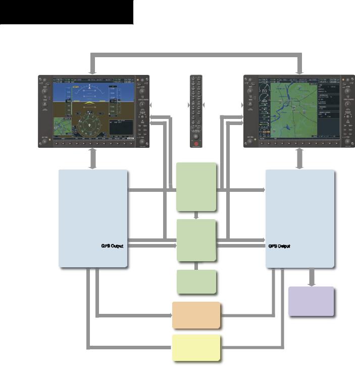
The LRUs are further described in the following section. All LRUs have a modular design, which greatly eases troubleshooting and maintenance of the G1000 system. A top-level G1000 block diagram is given in Figure 1-1. Additional or optional interfaces are depicted in Figure 1-2.
 NOTE: Please refer to the Pilot’s Guide Appendices for detailed specifications regarding the G1000 LRUs.
SYSTEM OVERVIEW
1.2LINE REPLACEABLE UNITS
•GDU 1040 – The GDU 1040 features a 10.4-inch LCD display with 1024 x 768 resolution. The left display is configured as a PFD and the right display is configured as an MFD. Both GDU 1040s link and display all functions of the G1000 system during flight. The displays communicate with each other through a High-Speed Data Bus (HSDB) Ethernetconnection. Eachdisplayisalsopairedvia an Ethernet connection with a GIA 63 Integrated Avionics Unit.
•GMA1347–TheGMA1347AudioPanelintegrates NAV/COM digital audio, intercom system and marker beacon controls. The GMA 1347 also controls manual display reversionary mode (red DISPLAY BACKUP button) and is installed between the MFD and the PFD. The GMA 1347 communicates with both GIA 63s using an RS-232 digital interface.
190-00498-00 Rev.A |
Garmin G1000 Pilot’s Guide for Cessna Nav III |
1-1 |

SYSTEM OVERVIEW
•GIA 63 – The GIA 63 is the central Integrated Avionics Unit (IAU) of the G1000 system. The GIA 63 functions as a main communication hub, linking all LRUs with the PFD and the MFD displays. EachGIA 63containsaGPSreceiver,VHF COM/NAV/GS receivers, and system integration microprocessors. Each GIA 63 is paired with a respective GDU 1040 display through Ethernet. The GIAs are not paired together and do not communicate with each other directly.
•GRS 77 – The GRS 77 is an Attitude and Heading Reference System (AHRS) that provides aircraft attitude and heading information to both the G1000 displays and the GIA 63s. The unit contains advanced sensors, accelerometers and rate sensors. In addition, the GRS 77 interfaces with both the GDC 74A Air Data Computer and the GMU 44 Magnetometer. The GRS 77 also utilizes GPS signals sent from the GIA 63. Attitude and heading information is sent using an ARINC 429 digital interface to both GDU 1040s and GIA 63s. AHRSmodesofoperationarediscussedlaterinthis document.
•GMU 44 – The GMU 44 Magnetometer measures local magnetic field information. Data is sent to the GRS 77 AHRS for processing to determine aircraft magneticheading. Thisunitreceivespowerdirectly from the GRS 77 and communicates with the GRS 77 using an RS-485 digital interface.
•GDC 74A – The GDC 74A Air Data Computer processes information from the pitot/static system aswell astheoutside air temperature (OAT)sensor. The GDC 74A provides pressure altitude, airspeed, vertical speed and OAT information to the G1000 system, and communicates with the GIA 63s, GDU 1040sandGRS 77usinganARINC 429digital interface.
•GEA71–TheGEA71receivesandprocessessignals from the engine and airframe sensors. Sensor types includeenginetemperatureandpressuresensorsas wellasfuelmeasurementandpressuresensors. The GEA 71 communicates with both GIA 63s using an RS-485 digital interface.
1-2 |
Garmin G1000 Pilot’s Guide for Cessna Nav III |
190-00498-00 Rev.A |

• GTX 33 – The GTX 33 is a solid-state, Mode- S transponder that provides Modes A, C and S operation. The GTX 33 is controlled through the PFDandcommunicateswithbothGIA 63sthrough an RS-232 digital interface.
SYSTEM OVERVIEW
•GDL 69/69A – The GDL 69/69A is an XM satellite radio receiver that provides real-time weather information to the G1000 MFD. The GDL 69A also provides digital audio entertainment in the cockpit. The GDL 69/69A communicates with the MFD on the High-Speed Data Bus. A subscription to the XM Satellite Radio service is required for the GDL 69/69A to be used.
190-00498-00 Rev.A |
Garmin G1000 Pilot’s Guide for Cessna Nav III |
1-3 |
SYSTEM OVERVIEW
High-Speed Data Bus (Ethernet)
GDU 1040 (PFD)
No. 1 GIA 63
Integrated Avionics Unit
System Inegration Processors
I/O Processors
VHF COM
VHF NAV/LOC
GPS
Glideslope
GPS Output
GMA 1347
Audio Panel
Reversionary |
|
Reversionary |
Control |
|
Control |
|
|
|
|
|
|
GDC 74A
Air Data
Computer
OAT
Airspeed
Altitude
Vertical Speed
GRS 77
AHRS
Attitude
Rate of Turn
Slip/Skid
GMU 44
Magnetometer
Heading
GTX 33
Transponder
GEA 71
 Engine/Airframe
Unit
GDU 1040 (MFD)
No. 2 GIA 63
Integrated Avionics Unit
System Integration Processors
I/O Processors
VHF COM
VHF NAV/LOC
GPS
Glideslope
GPS Output
Ho ell KAP 140
Autopilot
(If equipped)
Figure 1-1 Basic G1000 System
1-4 |
Garmin G1000 Pilot’s Guide for Cessna Nav III |
190-00498-00 Rev.A |
SYSTEM OVERVIEW
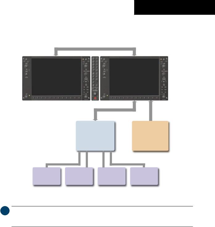
High-Speed Data Bus (Ethernet)
No. |
63 |
Integrated Avionics Unit
GDL 69/69A
System Integration Processors |
Data Link |
|
I/O Processors |
||
Real-time Weather |
||
VHF COM |
||
Digital Audio Entertainment |
||
VHF NAV/LOC |
||
|
||
GPS |
|
|
Glideslope |
|
L3 |
Honeywell |
Honeywell |
CO Guardian |
|
Stormscope |
||||
KR 87 |
KN 63 |
Carbon Monoxide |
||
Lightning Strike and |
||||
ADF Receiver |
DME |
Detection |
||
Thunderstorm Detection |
||||
|
|
|
Figure 1-2 G1000 Optional Interfaces
 NOTE: For information on all optional equipment shown in Figure 1-2, please consult the applicable user’s guide supplied with the optional equipment. This document assumes that the reader is already familiar with the operation of this additional equipment.
190-00498-00 Rev.A |
Garmin G1000 Pilot’s Guide for Cessna Nav III |
1-5 |

SYSTEM OVERVIEW
This page intentionally left blank.
1-6 |
Garmin G1000 Pilot’s Guide for Cessna Nav III |
190-00498-00 Rev.A |