

- 11 -
ANGDIR=counterclockwise ANGBASE=0 Select objects: Specify opposite corner: 6 found Select objects: Specify base point:
Specify rotation angle or [Reference]: 90 «Enter»
Command: _ucs
Current ucs name: *NO NAME* Enter an option [New/Move/ orthoGraphic/Prev/Restore/Save/ Del/ Apply/?/World] <World>: _x
«Enter»
Specify rotation angle about X axis <90>: «Enter»
Command:
Command: Command: _point
Current point modes: PDMODE=98 PDSIZE=0.0000 Specify a point:
25,-15 «Enter»
Command: Command: _point
Current point modes: PDMODE=98 PDSIZE=0.0000 Specify a point:
60,25 «Enter»
Command: Command: _point
Current point modes: PDMODE=98 PDSIZE=0.0000 Specify a point:
0,25 «Enter»
Command:
Вводим вспомогательные точки в вершинах контура призматического выреза
(рис.13).
Сначала выбирается тип точки:
Format/ Point style
Затем по координатам строятся точки (координаты точек можно определить по размерам чертежа, см. рис.17:
Draw/Point/ Single point
Command: _point
Current point modes: PDMODE=98 PDSIZE=0.0000 Specify a point:
0,10 «Enter»
Command: Command: _point
Current point modes: PDMODE=98 PDSIZE=0.0000 Specify a point:
10,10 «Enter»
Command: Command: _point
Current point modes: PDMODE=98 PDSIZE=0.0000 Specify a point:
10,-15 «Enter»
Строим твердотельную модель призмы, участвующей в формообразовании детали (рис.14), в следующем порядке.
Строим через введенные точки рис.13) замкнутый контур (тип линии– polyline).
Screen Menu/ Draw 1/
Pline
Рис.14
Command: _pline
Specify start point: 0,35 «Enter»
Current line-width is 0.0000 Specify next point or [Arc/Close/ Halfwidth/ Length/Undo/Width]: 10,35 Specify next point or [Arc/Close/ Halfwidth/Length/Undo/Width]:
10,10
- 12 -
Specify next point or [Arc/Close/ Halfwidth/Length/Undo/Width]: Specify next point or Specify next point or [Arc/Close/ Halfwidth/ Length/Undo/Width]:
25,10 «Enter»
[Arc/Close/Halfwidth/Length/Und o/Width]: 60,50 «Enter» Specify next point or [Arc/Close/ Halfwidth/Length/ Undo/Width]: 0,50 «Enter» Specify next point or Arc/ Close/ Halfwidth/ Length/ Un-
do/Width]: c «Enter»
Command:
Создаем твердотельную модель «вспомогательной» призмы методом «выдавливания» (рис.14).
Screen Menu/ Draw 2/
Solids/ Extrude
Command: _extrude
Current wire frame density: ISOLINES=4
Select objects: 1 found Select objects:
Specify height of extrusion or [Path]: 70 «Enter»
Specify angle of taper for extrusion <0>: 0 «Enter» Command:
Вращаем пользовательскую систему координат вокруг оси «X» на 90О.
Для вращения используем пиктограмму из стандартной панели инструментов
Command: _ucs
Current ucs name: *NO NAME* Enter an option [New/Move/ orthoGraphic/ Prev/ Restore/ Save/Del/ Apply/?/World] <World>: _x «Enter»
Specify rotation angle about X axis <90>: «Enter»
Command:
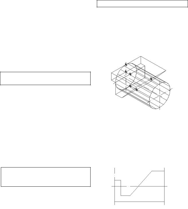
Перемещаем призму относительно цилиндра до совмещения их плоскостей симметрии (рис.15)
Screen menu/ Modify 2 /Move
Command: _move
Select objects: 1 found Select objects:
Specify base point or displacement: Specify second point of displacement or <use first point as displacement>: Command:
Рис.15
Вычитаем «вспомогательную» призму с помощью булевой операции. «Command: SUB-
TRACT» (рис.16).
Рис.16
- 13 -
Screen menu/Modify 2 /Subtract
Command: _subtract Select solids and regions to subtract from ..
Select objects: 1 found Select objects: Select solids
and regions to subtract Select objects: 1 found Select objects: «Enter»
Command:
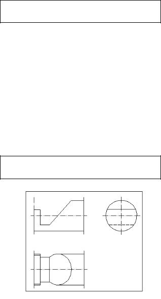
Выполняем построение чертежа детали в трех видах. Проводим осевые линии
(рис.1).
Screen menu/ Draw 2/
Solids/ Solview
Рис.17
Отметим, что при выполнении команды Solview автоматически формируются дополнительные слои: 3 слоя для каждого вида (один для линий видимого контура, один для линий невидимого контура и третий для простановки размеров на данном виде). Кроме того, создаётся слой для хранения плавающих экранов.
Сommand:_solview Regenerating lay-
out.Regenerating model.Enter an
option [Ucs/Ortho/ Auxiliary/Section]: u «Enter»
Enter an option [Named/World/?/ Current] <Current>: «Enter» Enter view scale 1>: «Enter» Specify view center: Specify view center <specify viewport>: Specify first corner of viewport: Specify opposite corner of viewport:
Enter view name: в1 «Enter»
«вид спереди»
UCSVIEW = 1 UCS will be saved with view Enter an option [Ucs/Ortho/ Auxiliary/Section]:
o «Enter»
Specify side of viewport to Specify view center:
Specify view center <specify viewport>: Specify first corner of viewport: Specify opposite corner of viewport:
Enter view name: в2 «Enter»
«вид сверху»
UCSVIEW = 1 UCS will be saved with view
Enter an option [Ucs/Ortho/Auxiliary/ Section]: o
Specify side of viewport to project:
Specify view center: Specify view center <specify viewport>: Specify first corner of viewport:
Specify opposite corner of viewport:
Enter view name: b3 «Enter»
«вид слева»
UCSVIEW = 1 UCS will be saved with view Enter an option [Ucs/Ortho/ Auxiliary/Section]:
«Enter»
Command:
Переходим от «объемного» представления детали к «плоскому».
- 14 -
Screen menu/ Draw 2/ Solids/ Soldraw
Command: _soldraw
Select viewports to draw.. Select objects: 1 found
Select objects:1 found,2 total Select objects 1 found 3 total Select objects: «Enter»
One solid selected. One solid selected. One solid selected.
Command: ltscale «Enter»
Enter new linetype scale factor <0.7000>: 0.8
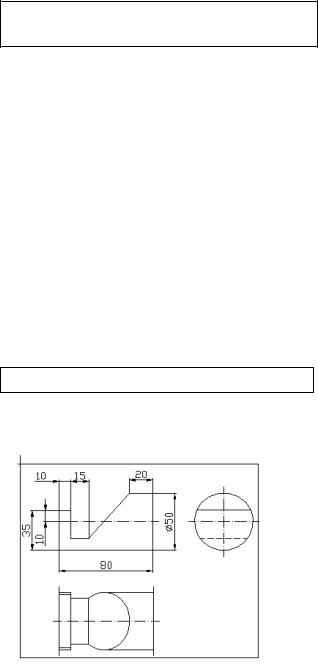
Ставим размеры на чертеже (рис.18).
Все размеры находятся в падающем меню
Dimension
Command:
Command: _dimlinear
Specify first extension
Рис.18
line origin or <select object>: Specify second extension line origin: Specify dimension line location or [Mtext/Text/ Angle/Horizontal/ Verticl/ Rotated]: Dimension text = 80 «Enter»
Command:
Command: dimlinear Specify first extension:
_saveas line origin or <select object>: Specify second extension line origin:
Specify dimension line location or [Mtext/Text/Angle/ Horizontal/Vertical/Rotated]:
Dimension text = 10 «Enter» Command:
Command: _dimlinear
Specify first extension line origin or <select object>: Specify second extension line origin: Specify dimension line loca tion or [Mtext/Text/ Angle/ Horizontal/ Vertical/Rotated]: Dimension text =
15 «Enter»
Command:
Command: _dimlinear
Specify first extension line origin or <select object>: Specify second extension line origin: Specify dimension line location or [Mtext/Text/ An gle/ Horizontal/Vertical/Rotated]:
sion text = 20 «Enter» Command:
Command: _dimlinear
Specify first extension line origin or <select object>: Specify second extension line origin: Specify dimension line location or [Mtext/Text/ Angle/ Horizontal/Vertical/Rotated]: Dimension text = 50 «Enter» Command:
Command: _dimlinear
Specify first extension line origin or <select object>: Specify second extension line origin: Specify dimension line location or [Mtext/Text/ Angle/ Horizontal/Vertical/Rotated]: Dimension text = 10 «Enter» Command:
Command: _dimlinear
Specify first extension line origin or <select object>: Specify second extension line origin: Specify dimension line location or Dimension text = 35
«Enter»
Command:

- 15 -
Записываем результат
File/ Save as
Command: _save as
- 15 -
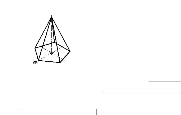
Упражнение 3 Пересечение поверхностей геометрических тел
плоскостями Построить три проекции пятиугольной пирамиды, усечен-
ной плоскостью «Р».
Построить натуральную величину сечения
Вводим параметры для настройки рабочего стола
AutoCAD (см. упр. 1).
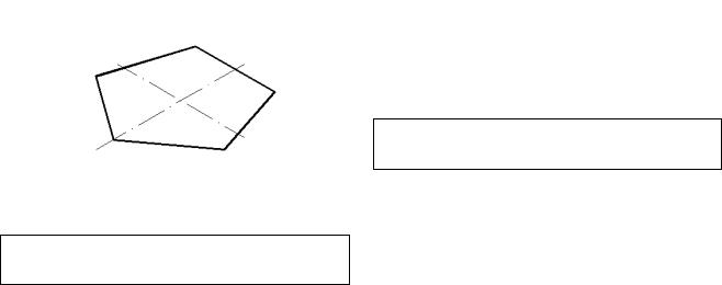
Строим правильный пятиугольник в качестве исходного контура для создания твердотельной модели пирамиды методом «выдавливания» (рис.19).
Рис. 19
Screen Menu/ Draw 1/
polygon
Command: _polygon
Enter number of sides <4>: 5
«Enter»
Specify center of polygon or [Edge]: 0,0 «Enter»
Enter an option [Inscribed in circle/Circumscribed about circle] <I>:
Specify radius of circle:
32«Enter»
Вращаем полигон на угол 450)(рис.19).
Command: _rotate
Current positive angle in UCS: ANGDIR=counterclockwise ANGBASE=0 Select objects: 1 found
Select objects: «Enter» Specify base point: 0,0
«Enter»
Specify rotation angle or [Reference]: 90 «Enter»
Command:
Строим осевые линии, см. упр.1.
Строим твердотельную модель пирамиды методом «выдавливания» (рис.20).
Screen Menu/ Draw 2/
/Solids/ Extrude
Command: _extrude
Current wire frame density: ISOLINES=4
Select objects: <Snap off> 1 found Select objects:
Specify height of extrusion or [Path]: 76 «Enter»
Specify angle of taper for extrusion <0>: 18.81 «Enter»
Отметим, что в последней команде вводится угол суже-
ния (18,810).
Вводим две вспомогательные базовые точки. Выбирается тип точки. [Format/ Point style]
- 16 -
Затем по координатам строятся точки (рис.20).
Draw/Point/ Single point
Command: _point
Current point modes: PDMODE=98 PDSIZE=0.0000 Specify a point:
<Osnap on> _int of
Command:
Command: _point Current point modes: PDMODE=98 PDSZE=0.0000 Specify a point: «Enter» Command:
Проводим недостающую ось симметрии.
Command: _line
Specify first point: 0,0,-5
«Enter»
Specify next point or [Undo]:
0,0,80 «Enter»
Command:
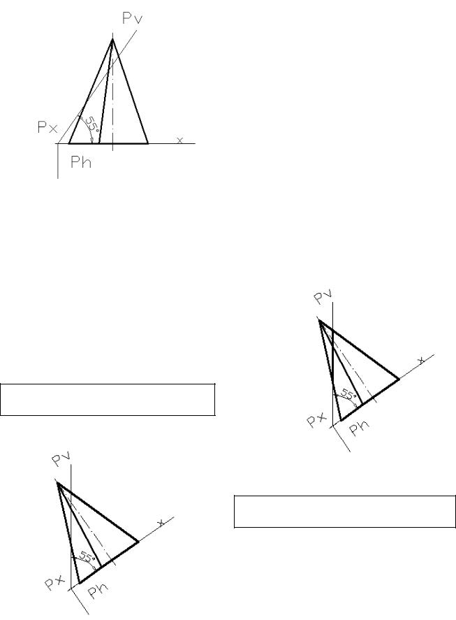
Проводим построение вспомогательных линий и наносим буквенные обозначения проецирующей плоскости «Р» (рис.21). Для построения
к бакоторая нахооснования зовой точке активизирова-
.
_nod of
or [Undo]: or [Undo]:
«Pv» на 0) рис.4).
Modify 2/
Command: _rotate
Current positive angle in UCS: ANGDIR=counterclockwise ANGBASE=0
Select objects: 1 found Select objects:
Specify base point: _nod of Specify rotation angle or [Reference]:
Command: Command: _line
Specify first point:
Specify next point or [Undo]: Specify next point or [Undo]: Command:
Command: _line Specify first point:
Specify next point or [Undo]: Specify next point or [Undo]: Command:
Command: _dtext
Current text style: "Standard" Text height: 2.5000
Specify start point of text or [Justify/Style]:
Specify height <2.5000>: 5 Specify rotation angle of text <0>: Enter text: Pv
Enter text: Ph
- 17 -
Enter text: Рx Enter text: x
Command:
Рис.21
Command: _dimangular
Select arc, circle, line, or <specify vertex>: <Snap off> Select second line: Specify dimension arc line location or [Mtext/Text/ Angle]: Dimension text = 55
Command:
Вращаем модель до совмещения направления следа Pv с направлением
оси "Y” (рис.22).
Screen Menu/ Modify 2/
Rotate
Command: _rotate
Рис.22
Current positive angle in UCS: ANGDIR=counterclockwise ANGBASE=0
Select objects: rotation angle or [Reference]: 35 «Enter» Command:
Устанавливаем систему координат в точку “Px”.
Command: _ucs
Current ucs name: *FRONT* Enter an option [New/Move/ orthoGraphic/ Prev/ Restore/Save/ Del/Apply/?/World]
<World>: _o
Specify new origin point <0,0,0>: _nod of Command:
Выполняем построение сечения в плоскости «P».
(рис.23).
Рис.23
Screen Menu/ Draw 2 /
Solids/Section
Command: _section Select objects: 1 found
Select objects: 1 found, 2 total Select objects: Specify first point on Section plane by YZ-plane <0,0,0>: _nod of

- 18 -
Specify a point on the «Enter» Command:
Перемещаем сечение параллельно плоскости «Р» на достаточное для выполнения последующего поворота расстояние (рис.24).
Screen Menu/
Modify 2/ Move
Command: _move
Select objects: 1 found Select objects: Specify base
point or displacement: _nod of Specify second point of displacement or <use first point as displacement>: Command:
Вращаем систему координат вокруг оси «X» на 900.
Вращение осуществляется командой UCS из стандартной панели инструментов
Command: _ucs
Current ucs name: *NO NAME* Enter an option [New/Move/ orthoGraphic/Prev/Restore/ Save/ Del/App./?/World]
<World>: _ x «Enter»
Specify rotation angle about X axis <90>: «Enter»
Command:
Рис.24
Вращаем сечение вокруг оси
«Z» на 900 (рис.25).
Command: _rotate
Current positive angle in UCS: ANGDIR=counterclockwise ANGBASE=0 Select objects: 1 found
Select objects: Specify base point: Specify rotation angle or [Reference]: 90 «Enter» Command:
Вращаем систему координат вокруг оси «X» на -900 .
Command: _ucs
Current ucs name: *NO NAME*Enter an option [New/Move/orthoGraphic/ Prev/Restore/Save/Del/Apply /?/World] <World>: _x «Enter» Specify rotation angle about X axis <90>: -90 «Enter» Command:
Рис.25
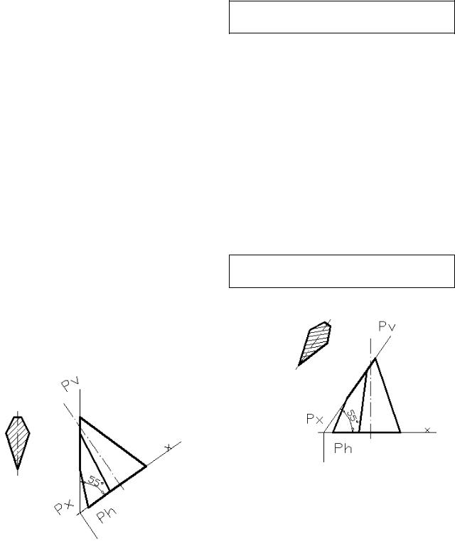
Выполняем штриховку сечения (рис.25).
Screen Menu/ Draw 2/ Solids/ Bhatch
Command: _bhatch
Select internal point: Selecting everything... visible... Analyzing the selected data...Analyzing internal islands...Select internal point: Command:
- 19 -
сечение) до совмещения направления следа Ph с направлением оси «Y»
(рис.27).
Command: _rotate
Проводим ось симметрии сечения (рис.25).
Command: _line Specify first point: <Osnap on> Specify next point or [Undo]: <Osnap off> Specify next point or [Undo]: Command:
Выполняем построение среза плоскостью «P»
(рис.26).
Screen Menu/ Draw 2 /Solids/ Slice
Command: _slice
Select objects: 1 found Select objects: Specify first point on licing plane by [Object/Zaxis/View/XY/YZ/ZX/ 3points] <3points>: yz
«Enter»
Specify a point on the YZplane <0,0,0>: _nod of Specify a point on desired Command:
Рис.26
Вращаем модель (включая
Screen Menu/ Modify 2/
Rotate
Current positive angle in UCS: ANGDIR=counterclockwise ANGBASE=0
Select objects: Specify Select objects: Specify base point:
_nod of
Specify rotation angle or [Reference]: -35 «Enter»
Command:
Устанавливаем начало координат в центр окружности, описанной вокруг правильного пятиугольника основания пирамиды.
Screen Menu/ Tools 2/
UCS/ Origin
Рис.27
Command: _ucs
Current ucs name: *FRONT* Enter an option [New/Move/orthoGraphic/Prev/ Restore/Save/Del/Apply/?/World] <World>: _o «Enter»