

laser_measurement_instruments_catalog
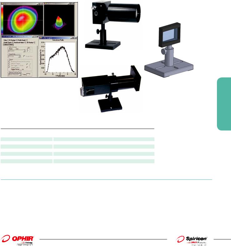
.pdfLBS-100 Attenuator
The LBS-100 system that is not as compact as the LBS-300 above but has larger aperture, and has versions for longer wavelengths. The system contains the mounting frame, 1 wedge beam splitter and several attenuators. The exit end of the LBS-100 is standard C mount thread so all our cameras can be mounted to the frame. The wedge angle is 6.5 degrees to insure that the reflection from the rear side will not enter the camera. The optical elements are flat to 1/4 wave in the visible to insure no distortion of the beam.
LBS-100 System
4X beam  reducer Camera
Incoming Beam LBS-100
LBS-100 to 4X beam reducer adaptor
The LBS beam splitter/attenuator system can be combined with the 4X beam reducer, as shown above, to attenuate and view large beams.
Ordering Information
Item |
|
Wavelength |
|
Absorber |
|
Neutral |
|
Wedge material |
|
Max power |
Clear aperture |
|
Dimensions |
|
P/N |
|
|
|
range |
|
material |
|
Densities or |
|
and reflection |
|
density on ND |
|
|
|
|
|
|
|
|
|
|
|
|
transmission |
|
|
|
filters |
|
|
|
|
|
|
LBS-100 |
|
400 - 900nm |
|
Neutral density |
0.3, 0.7, 1.0, 2.0, |
|
Fused Silica 4% in |
|
5W/cm2 for no |
19mm |
|
65mm W x 55mm |
|
SP90061 |
||
|
|
recommended, |
|
glass |
|
3.0, 4.0 ND at |
|
wavelength range |
|
distortion, 50W/ |
|
|
H x 140mm D |
|
|
|
|
|
functional to |
|
|
|
632nm |
|
400 - 900nm |
|
cm2 damage |
|
|
|
|
|
|
|
|
2600nm |
|
|
|
|
|
|
|
|
|
|
|
|
|
|
LBS-100 YAG |
|
1064nm |
|
Same |
|
Same |
|
1% at 1064nm |
|
Same |
|
Same |
|
Same |
|
SP90057 |
LBS-100 IR 0.5 |
|
10.6µm |
|
CaF2 flats,3 -3mm |
|
30% T for 3mm flat, |
|
ZnSe 0.5% at |
|
Same |
|
Same |
|
Same |
|
SP90058 |
|
|
|
|
and 1-1mm |
|
60% T for 1mm flat |
|
10.6µm |
|
|
|
|
|
|
|
|
|
|
|
|
|
|
at 10.6µm |
|
|
|
|
|
|
|
|
|
|
LBS-100 IR 5.0 |
|
10.6µm |
|
Same |
|
Same |
|
ZnSe 5% at |
|
Same |
|
Same |
|
Same |
|
SP90059 |
|
|
|
|
|
|
|
|
10.6µm |
|
|
|
|
|
|
|
|
Accessories |
|
|
|
|
|
|
|
|
|
|
|
|
|
|
|
|
|
|
|
|
|
|
|
|
|
|
|
|
|
|
|
||
LBS-100 filter set |
|
Replacement filter set |
|
|
|
|
|
|
|
|
|
|
|
SP90141 |
||
|
|
|
|
|
|
|
|
|
|
|
|
|
|
|
||
LBS-100 -YAG |
|
Replacement filter set |
|
|
|
|
|
|
|
|
|
|
|
SP90142 |
||
filter set |
|
|
|
|
|
|
|
|
|
|
|
|
|
|
|
|
LBS-100 to |
|
Mount L11058/L11059 camera to LBS-100 attenuator |
|
|
|
|
|
|
|
|
|
SP90196 |
||||
L11058/L11059 |
|
|
|
|
|
|
|
|
|
|
|
|
|
|
|
|
adaptor |
|
|
|
|
|
|
|
|
|
|
|
|
|
|
|
|
|
|
|
|
|
||||||||||||
LBS-100 to 4X |
|
This adapter enables mounting of the LBS-100 beam splitter/attenuator assembly in front of the 4X beam reducer. |
|
SPZ17029 |
||||||||||||
beam reducer |
|
The combined assembly can image large high power beams in one unit. |
|
|
|
|
|
|
|
|
||||||
adapter |
|
|
|
|
|
|
|
|
|
|
|
|
|
|
|
|
3.4.2 Beam Analysis
189
For latest updates please visit our website: www.ophiropt.com/photonics |
|
01.04.2014 |
3.4.3 Beam Splitter
3.4.3 Beam Analysis
190
Model |
|
Beam Tap l & ll |
|
Beam Tap l & ll YAG |
|
Stackable Beam Splitter |
|
Single & Dual Front-Surface |
|
|
|
|
Beam Samplers |
||||
|
|
|
|
|
|
|
|
|
Wavelength |
|
400-700nm |
|
1064nm |
|
190-2000nm |
|
200nm-2.5µm |
Reflection |
|
4% & 0.16% of incident beam |
|
0.5% & 0.0025% of incident beam |
|
5% & 0.25% of incident beam |
|
0.057% @ 532nm |
Clear aperture |
|
Ø17.5mm |
|
Ø17.5mm |
|
Ø15mm |
|
14mm x14mm |
Damage threshold |
|
5W/cm2 no distortion |
|
5W/cm2 no distortion |
|
>5J/cm2 |
|
100MW/cm2 |
Mounting |
|
C-Mount Threads |
|
C-Mount Threads |
|
C-Mount Threads |
|
C-Mount Threads |
|
|
|
|
|
|
|
|
|
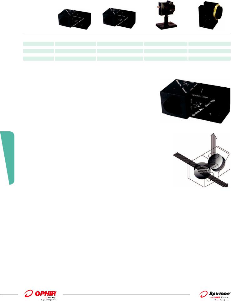
Beam Tap I & ll
ֺDual surface reflector for equalizing S & P polarization
ֺThe two planes of reflection are orthogonal
Single Surface Polarization Problems
A single surface reflection at 45° is often used to sample a laser beam for profile measurements or for monitoring power or energy. However, as shown on page 191, at 45° a single surface reflects the S polarization component at more than 10 times the reflection of the P component. Depending on the laser polarization content, or stability, this sampling can provide very misleading and unreliable measurements. (The BT-I-YAG has both surfaces A/R coated for 1064nm so the reflection for both polarizations is equal at 0.5%. At other wavelengths far from 1064nm the above discussion applies).
Equalizing S & P reflected polarization
Any arbitrary polarization component can be broken into equivalent S & P components. With complimentary sampling surfaces any given component gets reflected once as the S
polarization, and the second time as the P polarization. Thus using 2 surfaces, the total reflected energy for all polarization components is the sum of the S reflectance and the P reflectance. This causes the sampled beam to have S & P components that are identical to the original beam.
01.04.2014 |
|
For latest updates please visit our website: www.ophiropt.com/photonics |
|
Beam path through beam tap
The Beam Tap II uses two reflecting surfaces such that the two planes of reflection are orthogonal. The standard Beam Tap I rear surface is AR coated from 400-700nm.
This diagram shows the 6mm offset of the through beam that is created by the reflecting optic. The deflection angle of the output beam is less than 0.007 degrees. The rear surface of the flat is AR coated to maximize the throughput of the main beam. The standard Beam Tap II rear surface is AR coated for 400nm-700nm. The YAG version is AR coated for 1064nm on both surfaces.
Beam tap relection vs wavelength
Shown is the Beam Tap II final sampled reflection vs. wavelength.
As shown both the S & P reflection are nearly constant at 0.05% from the UV to the infrared. (See figure 7 in the Beam Tap manual in our website)
6mm Typical Beam Offset
Ordering Information
Model |
|
Surface |
|
Wavelength range |
|
Optical Material |
|
Reflection |
|
P/N |
BT-I |
|
Single surface, 1 cube |
|
400-700nm |
|
UVFS |
|
4% Ravg |
|
SP90135 |
BT-II |
|
Dual surface, 2 cubes |
|
400-700nm |
|
UVFS |
|
0.16% Ravg |
|
SP90133 |
BT-I-YAG |
|
Single surface, 1 cube |
|
1064nm |
|
BK7 |
|
0.5% Ravg |
|
SP90173 |
BT-II-YAG |
|
Dual surface, 2 cubes |
|
1064nm |
|
BK7 |
|
0.0025% Ravg |
|
SP90172 |
|
|
|
|
|
|
|
|
|
|
|
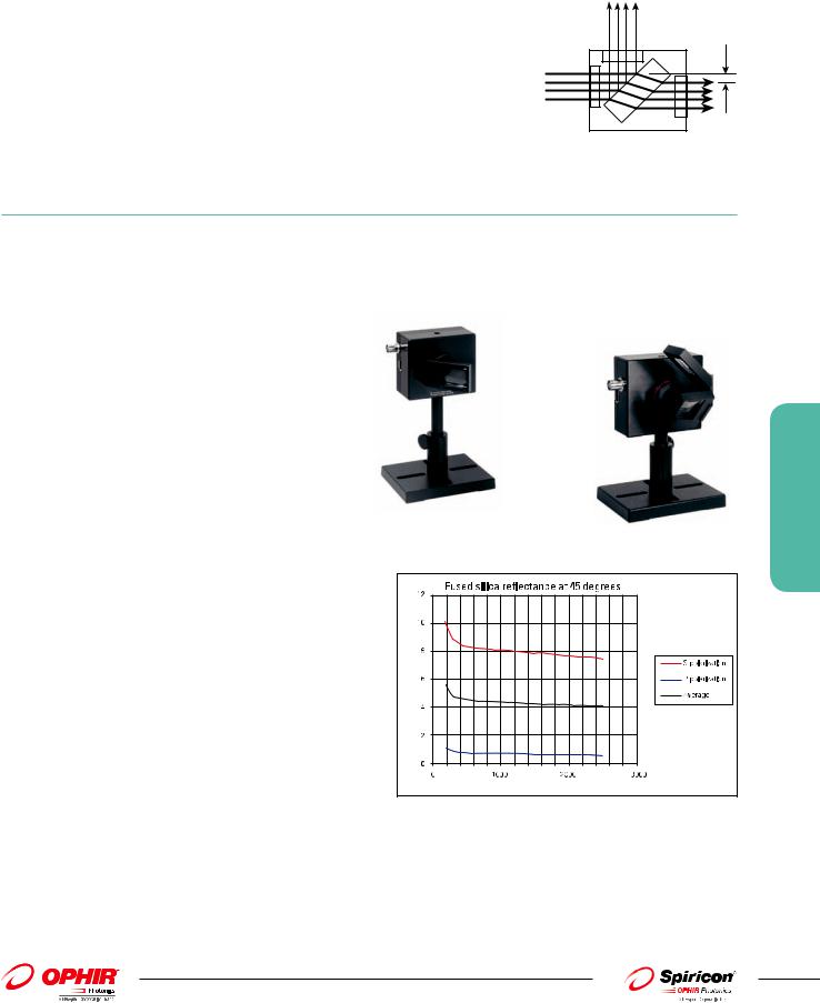
Stackable Beam Splitters
The stackable beam splitters are designed for maximum modularity and shortest beam path. They are compatible with almost all of our cameras having the standard C mount thread and can mount either to other attenuators or to the camera itself. Each beam splitter reduces the intensity of the beam by ~20 times (see graph below) so if a camera is equipped with filters that can operate with lasers typically up to ~1 Watt, with one beam splitter it can operate up to ~20 Watts and with two beam splitters up
to ~400W. The Beam Splitters will operate for wavelengths from 190nm to 2000nm. The damage threshold of the beam splitters is >5J/cm2 for 10ns pulses. The beam splitters are mounted over the fixed or variable attenuators with a simple fastening ring and can be oriented in any direction with the beam coming from right, left up, down ,or front.
The wedge angle of 10 degrees insures that only the reflection from the front surface will appear on the camera with no double images. The user must insure that there are beam stops for the transmitted and reflected beams.
Note that if possible, the user should use an even number of beam splitters so as to cancel any possible polarization effects.

 beam path
One beam splitter mounted |
Two beam splitters mounted |
Percent reflectance per surface |
\Wevelength (nm |
3.4.3 Beam Analysis
191
For latest updates please visit our website: www.ophiropt.com/photonics |
|
01.04.2014 |
3.4.3 Beam Analysis
192
Ordering Information
Item |
|
Description |
|
Clear |
|
Wavelength |
|
Reflectance |
|
Path length to |
|
P/N |
|
|
|
|
|
Aperture |
|
|
|
|
|
CCD with 3 |
|
|
|
|
|
|
|
|
|
|
|
|
|
screw-on ND |
|
|
|
|
|
|
|
|
|
|
|
|
|
filters |
|
|
|
|
|
|
|
|
|
|
|
|
|
|
|
|
|
1st Wedge Beam Splitter |
45 degree wedged beam |
Ø15mm |
400-700nm |
≤4% |
60mm |
SPZ17015 |
|
||||||
|
|
splitter |
|
|
|
|
|
|
|
|
|
|
|
2nd Wedge Beam Splitter |
|
Additional 45 degree wedged |
|
|
|
400-700nm |
|
≤4% |
|
93mm |
|
SPZ17026 |
|
|
|
beam splitter to mount to 1st |
|
|
|
|
|
|
|
|
|
|
|
|
|
wedge beam splitter |
|
|
|
|
|
|
|
|
|
|
|
Large aperature1st |
|
For converging beams a larger |
|
Ø30mm |
|
400-700nm |
|
≤4% |
|
60mm |
|
SPZ17025 |
|
Wedge Beam Splitter |
|
aperture 1st wedge beam |
|
|
|
|
|
|
|
|
|
|
|
|
|
splitter |
|
|
|
|
|
|
|
|
|
|
|
1st Wedge Beam Splitter |
|
45 degree wedged beam |
|
Ø15mm |
|
1064nm |
|
≤1% |
|
60mm |
|
SPZ17031 |
|
|
|
splitter |
|
|
|
|
|
|
|
|
|
|
|
2nd Wedge Beam Splitter |
|
Additional 45 degree wedged |
|
|
|
1064nm |
|
≤1% |
|
93mm |
|
SPZ17032 |
|
|
|
beam splitter to mount to 1st |
|
|
|
|
|
|
|
|
|
|
|
|
|
wedge beam splitter |
|
|
|
|
|
|
|
|
|
|
|
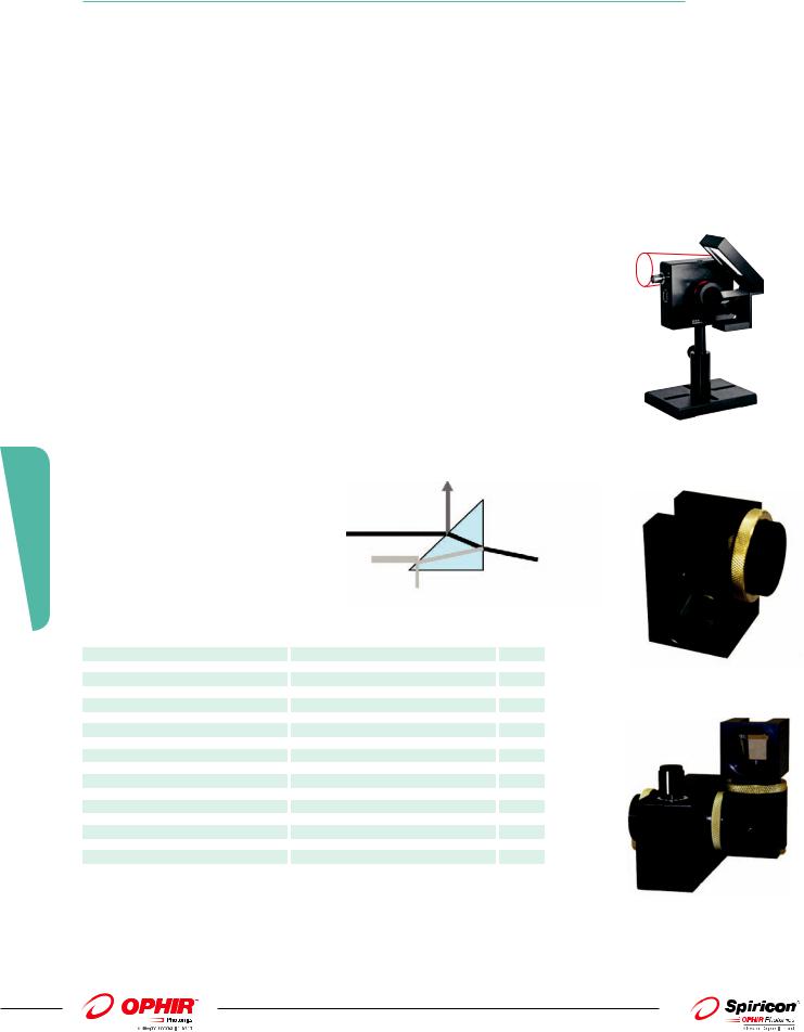
Single and Dual Prism Front-Surface Beam Samplers
The Prism Front-Surface Beam Sampler (PFSA) is a C-mount fixture housing a UV-Grade Fused Silica right angle prism, used for sampling the front surface reflection for high power/energy beam-profiling applications. Reflection at nominal incidence of 45°is polarization and wavelength dependent, with 532nm s-polarization reflected at 8.27%, and p-polarization at 0.68%.
The system is available as either a single prism ( PFSA) or dual orthogonal prism (DPFSA) unit. The dual orthogonal prism configuration results in polarization independent reflection of 0.057% at 532nm. Other filters and attenuators can be attached using the C-mount female threads at the input end. The use of a right-angle prism to sample the incident beam guarantees that any scattered secondary beams do not interfere with measurement, as shown in the sketch.
|
|
|
Reflected Beam |
|
|
|
|
|
|
Incident Beam |
|
|
|
|
|
|
Scattered Beams |
|
|
|
Prism Front Surface Attenuator Specifications |
|
|
||||
Wavelength of use |
|
|
200nm to ~2.5um |
|
|
|
Optical Material |
|
|
UV-Grade Fused Silica |
|
|
|
Surface Quality |
|
|
20-10 |
|
|
|
Surface Accuracy |
|
|
λ/10 |
|
|
|
Angle of Incidence |
|
|
45° |
|
|
|
Clear Aperture |
|
|
14mm x 14mm |
|
|
|
Reflection |
|
|
Polarization |
|
|
|
λ (nm) |
|
|
P |
S |
||
248.3 |
|
|
0.88% |
|
9.40% |
|
351.1 |
|
|
0.75% |
|
8.65% |
|
532 |
|
|
0.68% |
|
8.27% |
|
1064 |
|
|
0.64% |
|
8.01% |
|
Laser Damage Threshold |
|
|
CW> 100MW/cm2 |
|
|
|
Dimensions( PFSA) |
|
|
38.1mm x 32.3mm x 29.5mm |
|
|
|
Dimensions (DPFSA) |
|
|
44.5mm x 40mm x 32.5mm |
|
|
|
Output Mounting with Brass Lock Ring |
C-Mount Male (1”-32 Thread Male) |
|
|
|||
Input Mounting |
|
|
C-Mount Female (1”-32 Thread Female) |
|
|
|
|
|
|
|
|
|
|
Ordering Information |
|
|
|
|
|
|
|
|
|
|
|
||
Model |
|
Surface |
P/N |
|||
PFSA |
|
Single Prism Front Surface Sampler |
|
PH00052 |
||
DPFSA |
|
Dual Prism Front Surface Sampler |
|
PH00053 |
||
|
|
|
|
|
|
|
With large beam splitter mounted showing how to image converging beam
Dual Prism Front Surface Sampler
Two Single Prism Front Surface Samplers mounted on a ATP-K Attenuator
01.04.2014 |
|
For latest updates please visit our website: www.ophiropt.com/photonics |
|
3.4.4 Beam Expanders Microscope Objectives
|
|
|
|
|
|
Model |
|
4X Beam Expander |
|
Beam Expander |
|
|
|
with UV Converter |
|
|
|
|
|
|
|
|
|
Wavelength |
193nm-360nm |
400-1800nm |
|
||
Beam Size Change |
|
4X Expansion |
|
4X, 6X, 12X, 22X |
|
Clear aperture |
|
1/4 the size of the CCD |
|
|
|
|
|
imager |
|
|
|
Mounting |
|
C-Mount Threads |
|
|
|
|
|
|
|
|
|
|
|
|
|
|
|
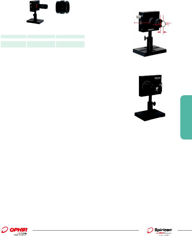
Screw on filters
Object plane 8mm in front of device
Camera with 4X Beam Expander
Beam expanders are available for 4.5mm spacing CS mount 12.5mm spacing cameras.
The 4X beam expander is an expanding telescope that images the beam as it looks at 8mm from the end of the expander onto the CCD while enlarging the image 4X. In addition to the 4X beam expander, other microscope objectives are available for expanding the beam even more. There are objectives for 6X, 12X and 22X expansion. The various expanders allow the use of our 2% and 10% filters as well as the variable attenuator so as to accommodate the camera to a wide range of source intensities .
With a camera having 4.4µm pixel spacing using the beam expander, the effective resolution can be as good as 0.5µm. The object plane that is imaged onto the CCD is located several mm in front of the assembly so even hard to get to focal spots and other small images are easy to image. The beam expanders are designed to accommodate up to 3 screw on filters or a variable attenuator behind them so a wide range of intensities can be accommodated.
For intensities too large to be accommodated by just filters, beam splitters are available to reduce the intensity before the beam expander. The beam expander is primarily intended for nonparallel beams such as focal spots and fiber tips. If small parallel beams are imaged, interference effects may occur.
The 4X Beam expander can also be fitted with a UV converter plate at its object plane so that you can look at small beams in the spectral range 193-360nm and expand them 4X. See ordering information for further details.
Microscope objective assembly with beam splitter mounted
3.4.4 Beam Analysis
193
For latest updates please visit our website: www.ophiropt.com/photonics |
|
01.04.2014 |

Shown is an image of the tip of a single mode fiber of 9µm diameter. The beam width as measured on the profiles shows 4X the actual size so we see a resolution of ~2µm.
UV converter assembly for 4X Beam Expander
Approximate |
|
Spectral range |
|
Distance from lens |
|
Distance from |
|
Distance of closest |
|
Total length of |
expansion ratio |
|
|
|
barrel to focus |
|
focus to 1st beam |
|
approach to focus |
|
assembly |
|
|
|
|
|
|
splitter |
|
with 1 beam splitter |
|
|
|
|
|
|
|
|
|
|
|
|
|
4X |
400 - 1800nm |
8mm |
18mm |
32mm |
50mm |
|||||
6X |
|
600 - 1064nm |
|
16mm |
|
10mm past 1st surface |
|
4.5mm |
|
107mm |
12X |
|
600 - 1064nm |
|
6mm |
|
6mm |
|
20mm |
|
101mm |
22X |
|
600 - 1064nm |
|
2.4mm |
|
8mm |
|
22mm |
|
102mm |
|
|
|
|
|
|
|
|
|
|
|
3.4.4 Beam Analysis
194
Ordering Information
Item |
|
Description |
|
P/N |
4X reimaging beam expander |
|
Screw optical assembly that images the plane 8 mm in front of the expander onto the CCD |
|
SPZ17022 |
|
|
while enlarging it 4X. Fits 4.5mm recess and CS mount cameras. |
|
|
Fiber adapter bracket for 4X beam expander |
|
Screw on bracket to use with Ophir fiber adapters so fiber is held in correct position to image |
|
SPG01649 |
|
|
fiber tip onto camera. Will give exact focus with FC type fiber. |
|
|
UV converter assembly for 4X beam expander |
|
Screw on assembly which has UV plate that converts 193 - 360nm radiation to visible. This plate |
|
SPZ17019 |
|
|
is at the object plane of the 4X expander so it produces a 4X enlarged image on the CCD. |
|
|
6X expanding microscope objective |
|
Screw optical assembly that images the plane 16mm in front of the lens onto the CCD while |
|
SPZ08257 |
|
|
enlarging it ~6X. Fits 4.5mm recess and CS mount cameras. Needs spacer assy below. |
|
|
12X expanding microscope objective |
|
Screw optical assembly that images the plane 6mm in front of the lens onto the CCD while |
|
SPZ08259 |
|
|
enlarging it ~12X. Fits 4.5mm recess and CS mount cameras. Needs spacer assy below. |
|
|
22X expanding microscope objective |
|
Screw optical assembly that images the plane 2.6mm in front of the lens onto the CCD while |
|
SPZ08260 |
|
|
enlarging it ~22X. Fits 4.5mm recess and CS mount cameras. Needs spacer assy below. |
|
|
Spacer assy for objectives |
|
Spacer assembly for above. One only needed for all expanders above. |
|
SPZ08261 |
Beam splitter for expanders above |
|
45 degree angle wedge beam splitter which mounts onto beam expander. Reduces beam intensity |
|
SPZ17027 |
|
|
by ~20 times. For spectral range 190 – 2500nm. Introduces 35mm extra beam path to object plane. |
|
|
Additional beam splitter for above |
|
Additional beam splitter to mount to 1st beam splitter. |
|
SPZ17026 |
|
|
|
|
|
01.04.2014 |
|
For latest updates please visit our website: www.ophiropt.com/photonics |
|
3.4.5 Beam Reducers
4X Reimaging Beam Reducer
The 4X Beam Reducer is an imaging system that images the plane 30cm in front of the reducer onto the camera CCD sensor while reducing the size 4 times and inverting it. The beam reducer uses the 3 screw on attenuators provided with the camera. Since the intensity of a beam after reduction will be increased by 4x4=16 times, it is advisable to attenuate the beam more than you would without beam reduction. This can be done with additional external beam splitters and attenuators which are available (see ordering information).
Note that the custom designed beam reducer gives better image quality than tapered fibers since it does not introduce graininess or uneven pixel response. Also the image distortion of ~1% is considerably lower than with most tapered fibers. The beam reducer is not compatible with CS mount cameras.
4X beam reducer |
Optional large wedge |
|
beam splitter |
Shown is an image of an Alexandrite laser with beam diameter of 18mm. As can be seen, it is easily seen with the FX50 camera with the 4X beam reducer.
LBS-100 combined with 4X beam reducer
The 4X beam reducer can be combined with the LBS-100 beam splitter/attenuator system to attenuate higher power beams before reducing them in size
Specifications of 4X beam reducer |
|
|
|
Spectral Range |
390nm to 1100nm |
Antireflection Coating |
Antireflection coating optimized for 1064nm and 532nm |
Beam reduction Accuracy |
± 3% |
Size |
Ø60 mm dia x 94mm length |
Aperture |
50mm |
Maximum Beam Size |
SP 503/FX50: 25x19mm, FX 33: 18x14mm, SP 620 or GRAS20: 28x21.2mm |
Distortion of Beam |
Less than 1% over 80% of diameter |
Damage Threshold |
30mJ per pulse for nanosecond pulses |
|
|
Ordering Information
4X Imaging Beam Reducer
Item |
|
Description |
|
P/N |
|
|
|
|
|
|
|
4X reimaging beam reducer |
Screw on beam reducer for beams in the wavelength region 360 – 1100nm that reimages the beam 30cm in front of the |
SPZ17017 |
|
||
|
|
unit onto the CCD while reducing the beam size 4X. Entrance aperture is 50mm. Fits 4.5mm recess cameras only. |
|
|
|
Accessories |
|
|
|
|
|
Filter holder and 50x50 filter |
|
Filter holder with set of 4 standard Schott 50X50mm neutral density filters. Useful to further reduce intensity after |
|
SPZ08240 |
|
set for 4X beam reducer |
|
beam splitter before inputting into 4X beam reducer. Mounts to standard ¼” thread, ½” diameter laboratory rod. |
|
|
|
LBS-100 to 4X beam reducer |
|
This adapter enables mounting of the LBS-100 beam splitter / attenuator assembly in front of the 4X beam reducer. |
|
SPZ17029 |
|
adapter |
|
The combined assembly can image large high power beams in one unit. |
|
|
|
|
|
|
|
|
|
Beam splitter large wedge |
|
Wedge, UVes, 44X32 mm, uncoated wedge housing mounts to 1/4” thread, 1/2” diameter laboratory rod (not included) |
|
SPZ17018 |
|
|
|
|
|
|
|
3.4.5 Beam Analysis
195
For latest updates please visit our website: www.ophiropt.com/photonics |
|
01.04.2014 |
3.4.6 CCTV lens for front imaging through glass or reflected surface
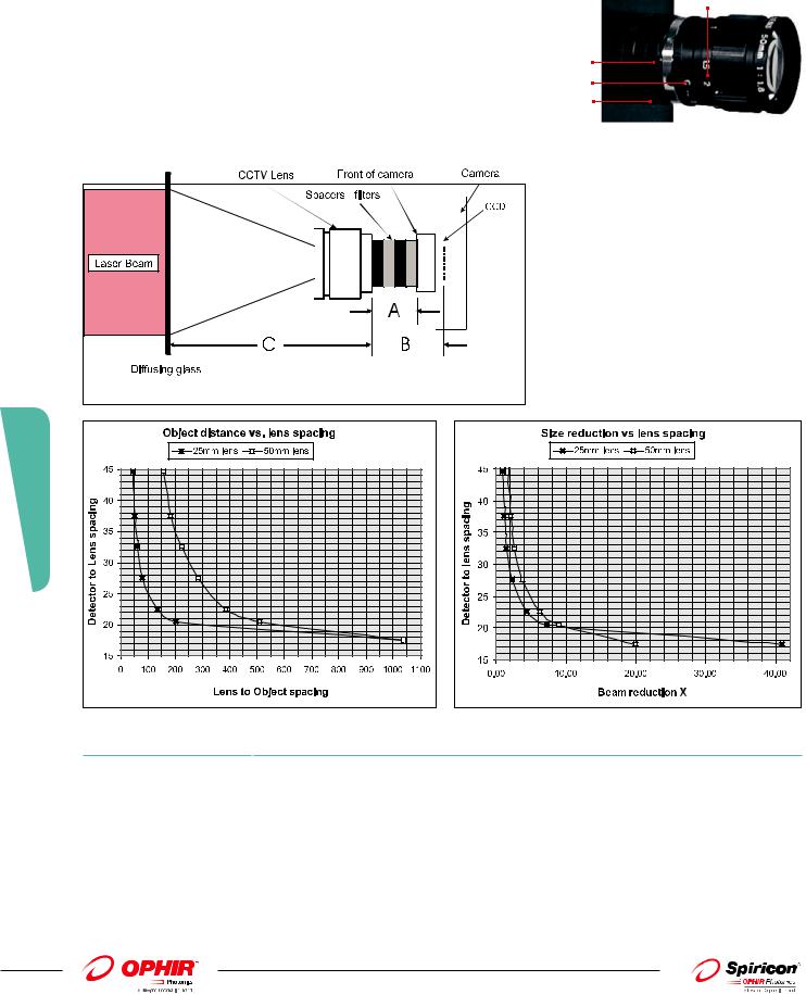
When direct imaging in front of the camera, for example, an image projected onto a diffusing surface, such as a ground glass plate, it is necessary to reduce the image so that it completely fits onto the CCD chip surface. The 25mm and 50mm CCTV lenses image an object from a given plane in front of the lens onto the CCD while reducing the size. The lens can image such objects at distances from about 10cm in front of the lens (20cm for the 50mm lens) to 1 meter or more depending on the distance from the lens to the camera. The distance from lens to camera depends on the camera type and spacers placed between the lens and the camera.
Focus adj
Spacers
Iris adj
Camera
Body
A.
B.
C.
-Total length of spacers added to system
-Detector to Lens spacing. Distance ‘A’ plus the CCD inset for the camera type
-Lens to Object spacing
|
|
CCD inset for Camera Types |
|
|
C mount (Camera front to CCD = 17.5mm) for nominal |
|
|
lens magnification, use without spacers. |
|
|
CS mount (Camera front to CCD = 12.5mm) for nominal |
|
|
lens magnification, use 5mm spacer. |
|
|
SP mount (SP cameras. Camera front to CCD = 4.5mm) |
|
|
for nominal lens magnification, use with 13mm spacers. |
3.4.6 Beam Analysis |
|
|
Ordering Information |
|
|
Item |
Description |
P/N |
25mm focal length CCTV lens kit |
|
25mm focal length lens assembly with locking iris and focus adjustment. Includes 1 ea 8mm spacer and |
SP90085 |
|
|
2 ea 5mm spacers |
|
50mm focal length CCTV lens kit |
|
Same as above except 50mm focal length lens |
SP90038 |
4mm spacer |
|
Screw on spacer to add 4mm spacing to optical system |
SPG01698 |
5mm spacer |
|
Screw on spacer to add 5mm spacing to optical system |
SPG02106 |
8mm spacer |
|
Screw on spacer to add 8mm spacing to optical system |
SPG02067 |
|
|
|
|
196
01.04.2014 |
|
For latest updates please visit our website: www.ophiropt.com/photonics |
|
3.4.7 Imaging UV lasers
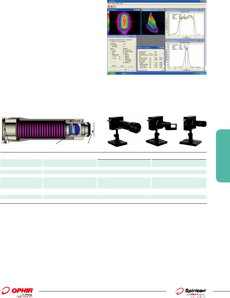
Integral Reimaging UV Image Converters
The UV image converters are fluorescent plates that convert UV radiation that is poorly imaged by silicon cameras into visible light that is then imaged onto the CCD of the camera. These fluorescent plates are specially designed for UV conversion and have a high light output, wide linear dynamic range and high damage threshold. There are 3 versions available:
1. The 4X UV image converter for large beams converts to visible and then images onto the CCD while reducing the beam size 4X.
2. The 1:1 UV image converter converts to visible and images the
beam onto the CCD without changing the size.
Shown here is a profile of a 248mm Excimer laser beam
3.The 4X expander with UV converter converts to visible and images a beam enlarged 4X onto the CCD.
All of the above imagers allow a beam splitter to be mounted at 45 deg angle in front of the imager so as to allow imaging of higher power/energy beams.
Cross section of 4X reducing UV image Converter
4X beam reducing UV Image Converter as mounted on camera
Fluorescent plate |
Imaging optics |
Image plane at CCD |
1X UV Image |
4X beam expander |
Converter |
with UV converter |
with Optional |
|
Beam Splitter |
|
Specifications |
|
4X UV Image Reducing Converter |
|
|
|
Beam Reduction |
4X reduction ±2% with included |
|
|
|
correction factor |
Resolution |
|
50µm x 50µm |
Spectral range |
|
193 to 360nm |
Minimum signal |
|
~1µJ/cm2 with blank filter |
Saturation intensity |
|
~30mJ/cm2 at 193nm, ~15mJ/cm2 at |
|
|
248nm with included filter 20 times above |
|
|
values with optional beam splitter |
Effective Aperture |
|
Ø30mm but effective beam size is |
|
|
limited to 4X CCD dimensions |
Damage threshold |
|
100W/cm2 or 2J/cm2 with beam splitter |
Dimensions |
|
Ø50mm dia x 185mm length |
1X UV Image Converter
1:1 imaging ±2% with included correction factor
35µm x 35µm
~15mJ/cm2 at 193nm, ~20mJ/cm2 at 248nm with included filter, 20 times greater with optional beam splitter
Ø18mm but effective beam size is limited to CCD dimensions
Ø31mm dia x 120mm length
4X Beam Expander with UV converter
4X expansion ±2% with included correction factor
15µm x 15µm
~30mJ/cm2 at 193nm, ~15mJ/cm2 at 248nm 20 times above values with optional beam splitter
1/4 the size of the CCD dimensions
Ø29mm dia x 69mm length
Ordering Information
Item |
|
Description |
|
P/N |
1X UV image converter |
|
Screw on imaging telescope that converts UV image to visible and images same size on CCD. For beam intensities |
|
SPZ17023 |
|
|
from 50µJ/cm2 to 15mJ/cm2. Fits 4.5mm recess and CS mount cameras. |
|
|
Beam splitter for above |
|
45 degree wedged beam splitter to reduce intensities on image converter by ~20X. For beam intensities of up to 300mJ/cm2 at 193nm. |
|
SPZ17015 |
4X reducing UV image |
|
Screw on imaging telescope that converts UV image to visible reduces the size 4X and images on CCD. For beam |
|
SPZ17024 |
converter |
|
intensities from 1µJ/cm2 to 15mJ/cm2. |
|
|
Beam splitter for above |
|
45 degree wedged beam splitter to reduce intensities by ~20X. For beam intensities of up to 300mJ/cm2 at 193nm. |
|
SPZ17007 |
UV converter assembly |
|
Screw on assembly which has UV plate to convert 193 - 360nm radiation to visible. The plate is at the object plane of |
|
SPZ17019 |
for 4X beam expander |
|
the 4X expander (P/N SPZ17022) and produces a 4X enlarged image on the CCD. |
|
|
20mm diameter UV |
|
Ø20mm diameter UV image conversion plate only. For customers that have own imaging system. Converts UV |
|
SPF01177 |
imaging plate |
|
image to visible. For beam intensities 50μJ/cm2 to 10μJ/cm2. |
|
|
30mm diameter UV |
|
Ø30mm diameter UV image conversion plate only. For customers that have own imaging system. Converts UV |
|
SPF01150 |
imaging plate |
|
image to visible. For beam intensities 50μJ/cm2 to 10μJ/cm2. |
|
|
50mm X 50mm UV |
|
50X50mm diameter UV image conversion plate only. For customers that have own imaging system. Converts UV |
|
SP90082 |
imaging plate |
|
image to visible. For beam intensities 1mJ/cm2 to 20mJ/cm2. Not suitable for 193nm. |
|
|
100mm X 100mm UV |
|
100X100mm diameter UV image conversion plate only. For customers that have own imaging system. Converts UV |
|
SP90083 |
imaging plate |
|
image to visible. For beam intensities 1mJ/cm2 to 20mJ/cm2. Not suitable for 193nm. |
|
|
3.4.7 Beam Analysis
197
For latest updates please visit our website: www.ophiropt.com/photonics |
|
01.04.2014 |
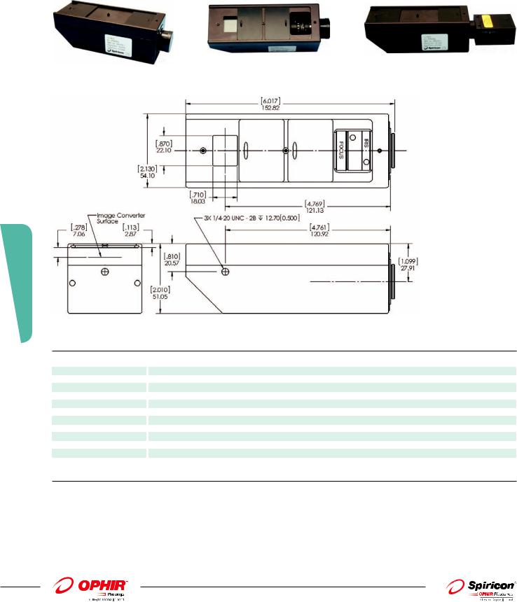
UView Ultraviolet Converter for C-mount Cameras
The UView accessory converts ultraviolet radiation into a visible green beam profile that is reimaged onto a CCD style C-mount camera. The UView operates over the ultraviolet region of 190-390nm. It has a reimaging magnification factor of ~0.5x and a field of view (FOV) of ~15x20mm with an SP620 style camera. The FOV will vary with camera format. Camera and software sold separately.
UView |
UViewtop view |
UViewwith camera (sold separately\ |
3.4.7 Beam Analysis
UView Image Converter specifications
Specifications |
|
|
|
Beam redactions |
~ 0.50X nominal image reduction |
Scale factor |
~ 2.0 nominal scale factor for BeamGage, see label |
Spectral range |
190 to 390nm |
Minimum signal |
~ 1uJ/cm2 |
Camera saturation1 |
~ 30mJ/cm2 at 193nm, ~ 15mJ/cm2 at 248nm Varies with wavelength and camera type |
Clear apreture |
18mm X 22mm |
Effective apretute |
15mm X 20mm w/SP620, varies with camera format |
Damage threshhold |
5W/cm2 / 100mJ/cm2 |
Mounting |
3 1/4-20 threaded mounting points, see figure 11 |
Dimensions |
see figure 7 |
Weight |
Xxx oz. (yyy g )w/o camera |
Adaptable beam analyzer |
The Uview can be used with the following cameras employed by BeamGage, LBA and BeamStar products: (This product |
camera systems |
will work with any X/CS-mountcamera but the FOV will vary based on imager format) SP503, SP260, SCOR20, GRAS20, |
|
FX50, FX33, FX33HD, L070, L130, L230 |
1. The UV converter glass will damage before it becomes saturated
Ordering Information
Item |
|
Description |
|
P/N |
UView |
|
Uview, Accessory for C-mnt Cameras |
|
SP90322 |
198
01.04.2014 |
|
For latest updates please visit our website: www.ophiropt.com/photonics |
|