

Моделирование бизнес-процессов / Моделирование бизнес-процессов / ER-диаграмы / 0849315484 Entity-Relationship Diagrams
.pdfSo far our relational database has developed into (without the data): [Note:
The primary keys are underlined.]
MALL-Store
name store_name MALL
name address STORE
sloc sname snum STORE-dept
snum depts OWNER
so_ssn so_name so_off_phone so_address STORE MANAGER
sm_ssn sm_name sm_salary
This case study will be continued at the end of Chapter 4.
Chapter 4: Extending
Relationships/Structural Constraints
Overview
In Chapters 2 and 3, we introduced some components of ER diagrams, including entities, attributes, and relationships. It is really insufficient for requirements elicitation to define relationships without also defining what are called structural constraints. Structural constraints are information about how two (or more) entities are related to one another. There are two types of structural constraints: cardinality and participation.
In this chapter, in addition to the structural constraints of relationships, we want to introduce a grammar to describe what we have drawn. The grammar will help with the requirements elicitation process, as we will specify a template for the English that can be imposed on a diagram, which will in turn make us say exactly what the diagram means. This chapter develops steps 6 and 7 of the ER design methodology. Step 6 states the nature of a relationship in English, and step 7 discusses presenting the database (designed so far) to the user.
Mapping rules for relationships are also developed and discussed with examples and sample data. At the end of the chapter, we also continue the running case study that we began in Chapter 2 and continued in Chapter 3.

The Cardinality Ratio of a Relationship
Cardinality is a rough measure of the number of entities (one or more) that will be related to another entity (or entities). For example, there are four ways in which the entities AUTOMOBILE and STUDENT can be "numerically involved" in a relationship: one-to-one (1:1), many-to-one (M:1), one-to-many (1:M), and many-to-many (M:N).
One-to-One (1:1)
In this type of relationship, one entity is associated with one other entity, and vice versa. Take, for example, if in our drive relationship (shown in Figure 4.1), we stated that one automobile is driven by one student and one student drives one automobile, then the student/automobile relationship would be one-to-one, symbolically:
STUDENT:AUTOMOBILE :: 1:1
Figure 4.1: An ER Diagram of the STUDENT-AUTOMOBILE Database with the Relationship Name, drive, and Showing the Cardinality
Ratios
Diagramatically we can represent a 1:1 relationship as shown in Figure 4A (Batani, Ceri, and Navathe, 1992).
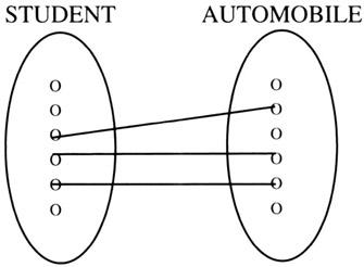
Figure 4A: A One-to-One Relationship
STUDENT:AUTOMOBILE::1:1
Many-to-One (M:1)
If the SA (STUDENT:AUTOMOBILE) relationship (shown in Figure 3.6) were many-to-one, we would say that many students are associated with one automobile and one automobile is associated with many students; that is:
STUDENT:AUTOMOBILE::M:1
We have intentionally used the verb phrase "is associated with" in place of drive because the statement "many students drive one automobile" can be taken in a variety of ways. Also, using a specific verb for a relationship is not always best when the diagram is first drawn, unless the analyst is absolutely sure that the verb correctly describes the user's intention. We could have also used the verb phrase "is related to" instead of "is associated with" if we wanted to be uncommitted about the exact verb to use.
We will tighten the language used to describe relationships presently, but what does an STUDENT:AUTOMOBILE::M:1 relationship imply? It would represent a situation where perhaps a family owned one car and that car was driven by multiple people in the family.
Diagramatically, we can represent a M:1 relationship as shown in Figure 4B (Batani, Ceri, and Navathe, 1992).

Figure 4B: Many-to-One Relationship
STUDENT:AUTOMOBILE::M:1
One-to-Many (1:M)
The sense of a one-to-many SA (STUDENT:AUTOMOBILE) relationship (shown in Figure 3.6) would be that a student is associated with many automobiles and an automobile is associated with one student. Clearly, if we define a relationship as 1:M (or M:1), then we need to be very clear about which entity is 1 and which is M. Here:
STUDENT:AUTOMOBILE::1:M
Diagramatically, we can represent a 1:M relationship as shown in Figure 4C (Batani, Ceri, and Navathe, 1992).
Figure 4C: One-to-Many Relationship
STUDENT:AUTOMOBILE::1:M
Many-to-Many (M:N)
In many-to-many relationships, many occurrences of one entity are associated with many of the other. Many-to-many is depicted as M:N, as in M of one thing related to N of another thing. Older database texts called this

an M:M relationship, but newer books use M:N to indicate that the number of things related is not presumed to be equal (the values of M and N are likely to be different).
If our SA relationship were many-to-many, a student would be associated with many automobiles and an automobile with many students:
STUDENT:AUTOMOBILE::M:N
In this case (if we assumed SA = drive, as shown in Figure 3.6), multiple students can drive multiple cars (hopefully not all at the same time) and multiple cars can be driven by multiple students. Picture, for example, a family that has multiple cars and any one family member can drive any of the cars and any car can be driven by any family member.
Diagramatically, we can represent an M:N relationship as shown in Figure 4D (Batani, Ceri, and Navathe, 1992).
Figure 4D: Many-to-Many Relationship
STUDENT:AUTOMOBILE::M:N
In expressing cardinality, this x:x ratio, where x = 1 or M(N), is called a cardinality ratio.
Which way do we depict the actual situation for our students and automobiles? This is a very interesting question. The answer is that we are to model reality as defined by our user. We listen to the user, make some assumptions, and draw the model. We then pass our model back to the user using a structured English that the user then approves or corrects.
A trap in ER design is to try to model every situation for every possibility. This cannot be done. The point of creating a database is normally a local situation that will be governed by the systems analysis (software engineering) process. In classical systems analysis, the analyst hears a user, creates a specification, and then presents the result back to the user. Here, the analyst (the database analyst/designer) models the reality that the user experiences — not what every database in the world should look like. If the user disagrees, then the analyst can easily modify the conceptual model, but there has to be a meeting of the minds on what the model is to depict.
In our STUDENT:AUTOMOBILE example, the choice we will make will be that one student is associated with (drives) one automobile. While clearly one can think of exceptions to this case, we are going to adopt a model, and the sense of the model is that we have to choose how we will identify the relationship between the entities as well as the information that we intend to
put in the entities themselves. Bear in mind that we are dealing with a conceptual model that could change, depending on the reality of the situation; however, we have to choose some sort of model to begin with, and the one we are choosing is a one-to-one relationship between students and automobiles.
In the Chen-like model, we will depict the one-to-oneness of this relationship by adding the cardinality numbers to the lines on the ER diagram that connect the relationships and the entities (see Figure 4.1).
In Figure 4.1 we put a "1" on the line between the entity box for the STUDENT and the diamond box for the relationship, and we put another "1" on the line between the diamond relationship and the entity box for the AUTOMOBILE. These 1's loosely mean that a student is related to one automobile and an automobile is related to one student. We must be quite careful in saying exactly what this relationship means. It does not mean that one student owns one automobile or a student pays insurance for an automobile. In our model, we mean that a student will drive, at most, one automobile on a college campus. Further, we are saying that an automobile will be driven by one and only one student. Because we are clarifying (refining) the database, we try to settle on the name of the relationship to include the concept that we are modeling — driving — by naming the relationship drive. Again, see Figure 4.1 for the renamed model with 1:1 cardinality.

Participation: Full/Partial
It is likely that on any campus, not all students will drive an automobile. For our model, we could assume that normally all of the automobiles on the campus are associated with a student. (We are for the moment excluding faculty and staff driving, and modeling the student/automobile relationship.)
To show that every automobile is driven by a student, but not every student drives an automobile, we will enhance our Chen-like model of ER diagrams by putting a double line between the relationship diamond and the AUTOMOBILE entity to indicate that every automobile is driven by one student. Put another way, every automobile in the database participates in the relationship. From the student side, we leave the line between the STUDENT entity and the relationship as a single line to indicate that not every student drives an automobile. Some students will not participate in the drive relationship because they do not drive a car on campus. The single/double lines are called participation constraints (a.k.a., optionality constraints) and are depicted in Figure 4.2.
Figure 4.2: An ER Diagram of the STUDENT-AUTOMOBILE Database with the Relationship Name, drive
The double line indicates full participation. Some designers prefer to call this participation mandatory. The point is that if part of a relationship is mandatory or full, you cannot have a null value (a missing value) for that attribute in relationships. In our case, if an automobile is in the database, it must be related to some student.
The single line, partial participation, is also called optional. The sense of
partial, optional participation is that there could be students who do not have a relationship to an automobile.
Checkpoint 4.1
1.What are structural constraints?
2.What kind of information does the cardinality ratio give us?
3.In how many different ways can two entities be involved in a cardinality relationship? Give examples.
4.What kind of information does the participation constraint give us?
5.Is it always necessary to have cardinality ratios as well as participation constraints in the same ER diagram? Why? Explain.
English Descriptions
We would now like to tighten the grammar that describes how a relationship affects entities using our structural constraints, and to adopt a standard way of stating the relationship. The standard language should appear on the model, or at least with it. Further, using a standard language approach to describe the ER diagrams allows us to not only close the loop with the user in the systems analysis process, but also facilitates feedback and "nails down" the exact meaning of the relationship.
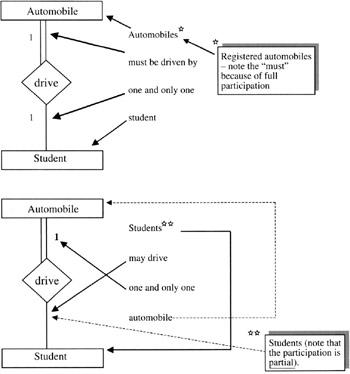
In the Chen-like model, the double lines define full participation, as in "automobiles fully participate in the drive relationship." Better yet, the double lines invite us to state the relationship as:
Automobiles must be driven by one (and only one) student.
The must part comes from the full (mandatory) participation and the one part from the cardinality.
The grammar for describing partial or optional relationship for the STUDENT entity to the AUTOMOBILE entity would be:
Students may drive one and only one automobile.
The may comes from the single line leaving the STUDENT entity box and the "one and only one" part comes from the cardinality. The point is that when expressing the sense of the ER diagrams, one uses the language that conveys what the relationship really means (i.e., students may drive one automobile and automobiles must be driven by one and only one student). A graphic on how to read an ER diagram is presented in Figure 4.3.
Figure 4.3: An ER Diagram of the STUDENT-AUTOMOBILE Database. Translating the Diagram into English