

Artificial Organs - Gerald E. Miller
.pdfDIALYSIS 45
Bowman's |
Na+ |
H2O |
Na+ |
H2O |
Aldosterone |
||
|
|
|
|
|
|
|
|
capsule |
|
|
|
|
|
|
|
|
Proximal |
|
|
|
|
||
|
tube |
|
|
|
Distal |
|
|
|
|
|
|
|
|
tubule |
|
Glomerulus |
|
|
|
Na+ |
|
|
|
|
|
|
|
|
ADH |
||
|
|
|
|
|
|
|
|
Glucose |
Amino |
H |
O |
Na |
+ |
H2O |
|
acids |
|
|
|||||
2 |
|
|
|
|
Collecting |
||
|
|
|
|
|
|
|
|
tubule
Loop of Henle
FIGURE 48: Movement of ions and water across the tubule system of the nephron as controlled by the hormones: aldosterone and ADH.
The loop of Henle operates by a countercurrent mechanism whereby the downward and upward sections are both contributing to the extracellular osmolarity, which is very high at the bottom of each loop and lessens toward the top of each loop. This occurs as ions are transported in both directions within each section of the loop, with most of the ion transport out of the loop at the bottom and into the loop at the top. The counter current mechanism allows the ascending loop to return fluid (and ions) into the descending loop and eventually into the extracellular fluid at the bottom of both loops. This fluid and ion mixture eventually finds its way back to the vasa recta.
The entire process of fluid flow and mass transfer across the glomerulus and through the tubule system is designed to transport a significant amount of fluid into the tubules with the bulk of it returning to the vasa recta. This process allows for selective retention of water and ions inside the tubules as controlled by hormones, which in turn allows for selective concentration of urine as is seen in Figure 48.
This approach—moving alot of fluid into the tubules to allow for a variable amount to be returned, cannot be duplicated by means of dialysis—the artificial cleansing of blood. Dialysis utilizes a standard transport of ions, metabolic wastes and water across a semipermeable membrane with this fluid mixture traveling across the membrane by means of simple diffusion, and not returning to the blood, as it does in the natural kidney.
4.2DIALYSIS PROCEDURE AND THE DIALYSIS SYSTEM
Dialysis is the artificial cleansing of blood to remove the same components as those removed by the natural kidney: metabolic waste products such as urea, ureic acid, and creatinine; excess ions; and excess water. This is accomplished by means of concentration gradient-driven diffusion for
46 ARTIFICIAL ORGANS
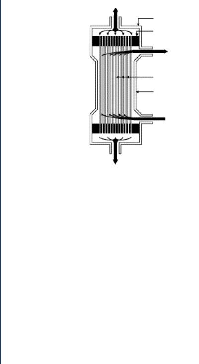
Blood inlet
Header
Tube sheet
Solution outlet
Fibers
Jacket
Solution inlet
Blood outlet
FIGURE 49: Capillary tube dialysis cartridge.
the first two components and by a pressure gradient for water. This process occurs within a capillary tube dialysis cartridge as is shown in Figure 49.
The cartridge is a polycarbonate canister containing 11 000 minute capillary tubes, each with pores small enough to allow transport of the three major blood components listed above, while too small to allow blood cells, large proteins, etc. to cross. In this fashion, the capillary tube pores are not unlike the glomerulus pores in the natural kidney nephron. The cartridge has upper and lower ports for blood to enter and exit the canister. Surrounding the capillary tubes is a fluid, called dialysate, which bathes the capillary tubes as serves as the recipient of the wastes, ions, and excess water which leaves the blood from within the capillary tubes. The dialysate is pumped from one side port of the cartridge and leaves from the other side port. The capillary tubes are typically composed of cellulose, which has been proven to be a biocompatible material. At the top and bottom of the capillary tube pack is a polyurethane “potting” section which appears to be a yellowish mass. In fact, this compound serves to briefly pool the incoming blood from the large inlet port so that it can more readily enter the minute capillary tubes. The reverse is true at the bottom of the capillary tubes where the blood enters the potting compound and then into the large outlet port. Dialysis cartridges come in many sizes and are matched to the size of the patient—from children to large adults as can be seen in Figure 50.

DIALYSIS 47
FIGURE 50: Capillary tube dialysis cartridges.
Dialysate is similar to clean blood, in that it has no waste products and has the normal level of ions. The typical dialysate mixture consists of the following normal level of blood ions:
NaCl |
5.8 g/L |
Na |
132 meq/L |
NaHO3 |
4.5 g/L |
K |
2.0 meq/L |
KCl |
0.15 g/L |
Cl |
105 meq/L |
CaCl2 |
0.18 g/L |
HCO3 |
33 meq/L |
MgCl2 |
0.15 g/L |
Ca |
2.5 meq/L |
Glucose |
2.0 g/L |
Mg |
1.5 meq/L |
The glucose is used to provide an osmotic gradient to assist in water transport from blood to dialysate. Blood with a high concentration of wastes and ions enters into the top of the dialysis cartridge with clean dialysate entering in the side port nearby. Along the length of the dialysis cartridge, simple diffusion takes place with wastes moving from the source of high concentration (blood) to the point of zero/low concentration (dialysate) across the capillary pores. Similarly, ion transport occurs from a high concentration (in the blood) to one of low concentration (in the dialysate). Water is transported from blood to dialysate by means of a concentration gradient of glucose assisted by a pressure gradient. A typical blood flow rate through the capillary tubes (as a whole) is 200 mL/min with the dialysate flow rate at 500 mL/min. The higher flow rate of dialysate ensures that dialysate with newly acquired waste products are quickly dispelled from
48 ARTIFICIAL ORGANS
|
|
Dialyzer inflow |
|
|
|
|
|
||
|
|
pressure monitor |
|
|
|
|
|
||
|
|
|
|
Venous |
|
||||
|
|
|
|
|
|
|
|
||
Heparin pump |
|
|
|
|
|
|
pressure monitor |
|
|
|
|
|
|
|
|
|
|
|
|
(to prevent |
|
|
|
|
|
|
|
||
clotting) |
|
|
|
|
|||||
|
|
|
|
|
|
|
|
|
|
|
|
|
Dialyzer |
|
|
Air trap and |
|||
|
|
|
|
|
|
|
|
||
|
|
|
|
|
|
|
|
air detector |
|
|
|
|
|
|
|
|
|
|
|
|
|
|
|
|
|
Air detector |
|||
|
|
|
|
|
|
clamp |
|
|
|
|
|
Arterial |
|
|
Clean blood |
||||
|
|
|
|
returned to |
|||||
|
|
pressure |
|
|
body |
||||
|
monitor |
Blood removed |
||
|
|
|||
|
|
for cleansing |
|
|
Blood pump |
|
|||
|
|
|||
|
|
|
|
|
FIGURE 51: Typical dialysis system.
the cartridge and replaced with clean dialysate, thus maintaining a large concentration gradient for mass transfer.
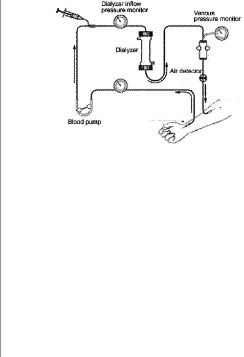
A typical dialysis system is shown in Figure 51. Blood access from the body is connected from needles to tubing, which is routed throughout the machine and into the dialysis cartridge. Blood from the bottom of the dialysis cartridge is then routed through the remainder of the tubing and onwards to return to the body. The dialysis machine consists of various sensors and monitors along with two key elements—a roller pump which pushes blood slowly along a tubing pathway (to avoid stagnation and resultant clotting) and bubble traps to allow any ambient air from remaining in the blood to cause an air embolism.
The dialysis cartridge and tubing set are disposed of following dialysis, although in some dialysis centers, the cartridge itself is cleaned and may be reused. This latter issue will be discussed in more detail in a subsequent section.
Blood is accessed from the radial artery in the forearm and returns to the cephalic vein. Typical chronic dialysis patients undergo dialysis three times per week for 4 h/session. This results in numerous insertions of needles into the forearm. Although the skin becomes tough after time, the underlying blood vessels do not. As a result, chronic dialysis patients often undergo a minor procedure whereby an arteriovenous graft is placed below the skin connecting the radial artery to the cephalic vein as is seen in Figure 52.
The graft not only protects the blood vessels from repeated needle insertions, but also connects the high pressure artery to the low pressure vein—keeping the vein from collapsing.

DIALYSIS 49
Looped graft
Artery
Vein
FIGURE 52: Arteriovenous graft in the forearm for chronic dialysis patients.
The pressure gradient from the artery to the vein also provides a gradient to propel blood through the tubing set and the dialysis cartridge. Thus, the roller pump within the dialysis system merely provides a boost for blood flow rather than having to provide the sole means of blood flow through the system.
A typical dialysis tubing set is shown in Figure 53 and includes bubble traps and sufficient tubing to connect from the artery/vein access needles to the dialysis machine, the dialysis cartridge, and back again to the forearm.
A typical dialysis machine is shown in Figure 54 with slots for the dialysis cartridge and bubble traps as well as an embedded roller pump and blood sensors.
FIGURE 53: Dialysis tubing set for the blood pathway.

50 ARTIFICIAL ORGANS
FIGURE 54: Dialysis machine.
The left-hand color-coded (blue and red) tubing is for the dialysate (clean and “dirty” ports). The slot to the right of this tubing is for the dialysis cartridge. To the right of the cartridge location is where the bubble traps are inserted. The roller pump is to the right of the bubble traps. At the bottom of the machine are two tubes with a tray below them. A dialysate concentrate jug is placed on the tray and one of the tubes is inserted into the jug. The machine draws dialysate concentrate from the jug, which is mixed with processed/treated water.
A typical dialysis center includes a water treatment room which converts municipal water into that which is clean enough to be used in close contact with blood. This water treatment includes a sediment filter, a water softener section, an ion exchanger section, an ultraviolet light to destroy bacteria, and a reverse osmosis unit which back-pressures water across an extremely fine (small pore) membrane to remove microscopic elements. The resulting treated water is sent to various patient treatment stations and each dialysis machine is connected to the water port via a hose located on the back of the machine. The mixture of treated water and dialysate concentrate is then transported to the dialysis cartridge through the front, color-coded tubing as was seen to the left of Figure 54.

DIALYSIS 51
A typical dialysis machine is approximately 60 inches high, 17 inches wide, 22 inches deep, and weights 190 pounds. It is on rollers to allow placement near the patient. The typical front-mounted screen displays the time on dialysis, time remaining, target water loss (in kg), water uptake rate (in kg/h), and blood pressure and/or heart rate.
4.3HISTORY OF DIALYSIS
Thomas Graham, Professor of Chemistry at Anderson’s University in Glasgow, coined the term dialysis in 1861. He noticed that crystalloids were able to diffuse through vegetable parchment coated with albumin (which acted as a semipermeable membrane). He called this “dialysis.” Using this method, he was able to extract urea from urine. In 1913, Abel, Rowntree, Turner, and colleague constructed the first artificial kidney. They used hirudin, produced from leeches obtained from Parisian barbers, as an anticoagulant. They passed animal blood from an arterial cannula through celloidin tubes that were contained in a glass “jacket.” The glass jacket was filled with saline or artificial serum. They coined the term “artificial kidney.” Blood was returned into the vein of the animal via another cannula. The inventors wrote, “this apparatus might be applied to human beings suffering from certain toxic states, especially if due to kidney damage, in the hope of tiding a patient over a dangerous chemical emergency.” The apparatus was never used to treat a patient (Robson JS, 1978). George Haas from Germany performed the first successful human dialysis in autumn 1924. The dialysis was performed on a patient with terminal uremia “because this was a condition against which the doctor stands otherwise powerless.” The dialysis lasted for 15 min, and no complications occurred.
The first practical human hemodialysis machine was developed by WJ Kolff and H Berk from the Netherlands in 1943. This rotating drum artificial kidney consisted of 30– 40 m of cellophane tubing in a stationary 100-L tank. It was Kolff who made clinicians and experimentalists interested in the treatment of uremia, and this machine delivered the effective hemodialysis treatments. This rotating drum machine is seen in Figure 55.
In 1946, Nils Alwall produced the first dialyzer with controllable ultrafiltration. It consisted of 10–11 m of cellophane tubing wrapped around a stationary, vertical drum made of a metal screen—resembling a rotating drum device stood on its end. In 1956, Kolff and Watschinger developed the principles of the Alwall machine to develop the “twin coil” artificial kidney (Figures), a modification of the “pressure cooker” dialyzer developed by Inouye and Engelberg in 1952. The first patients treated by dialysis were all believed to have acute renal failure. The methods in use for getting adequate flows of blood into the machine exhausted veins and arteries very quickly, and only a few dialysis treatments could be undertaken. The development of methods to use blood vessels repeatedly while preserving them made it possible to contemplate keeping a few patients alive for longer periods even though they had permanent

52 ARTIFICIAL ORGANS
FIGURE 55: Kolff rotating drum dialysis machine—the first practical hemodialysis system.
renal failure. The arteriovenous shunt was the key development. The first substantial program for dialysis of patients with chronic renal failure began in Seattle in the same year.
Home hemodialysis was introduced to overcome the difficulties in providing adequate facilities in hospitals for the increasing number of patients being put forward for treatment. If a relative provided help for the patient, it could be carried out without the use of doctors, nurses or hospital premises, extending the number of patients that could be treated, as well as being better for the patient. However, in 1965, at the American Society of Artificial Internal Organs meeting, reports of home hemodialysis of four patients in Boston and two in Seattle were supplemented by a report of two patients treated at home in London (Shaldon). All reported success and plans to expand their programs.
Today, hundreds of thousands of chronic dialysis patients undergo routine, periodic dialysis three times per week at local dialysis centers located throughout the nation. Dialysis represents one of the most successful organ replacement systems with millions of patients treated successfully for partial or total renal failure. Diabetes and heart disease remain principal causes for renal failure with alcohol and substance abuse also accounting for numerous cases.
4.4DIALYZER CARTRIDGE REUSE
Many local dialysis centers are privately operated facilities. Although dialysis conducted in hospitals for hospital patients (acute dialysis centers) results in single use of dialysis cartridges, many private facilities reuse cartridges. This entails the rinsing of the cartridge following patient dialysis, after which the cartridge is treated with a sterilant such as formaldehyde, gluteraldehyde, or renalin. Up to four cartridges are placed into a cleaning machine that provides several rinse steps and introduction of the sterilant. The patient’s name is written on the cartridge and the cartridge is placed into a bin where it will be stored until that patient needs it for the next session.

DIALYSIS 53
The cartridge is then rinsed several times before used for that patient. Although there is a capital expense in purchasing the cleaning machine along with supplies and manpower needed to rinse and sterilize the cartridges, there is a net modest savings rather than purchasing a new cartridge for every patient session. The cartridges cost $10–12 each and the dialysis facility is reimbursed at a set rate for each patient session by insurance, Medicare, or Medicaid. If there is a small net savings, even after expenses associated with cleaning and storing the cartridges, then the dialysis facility would show a large profit, given the number of patient sessions conducted each year. A typical dialysis center might have 20 patient stations. Each patient undergoes dialysis three times per week for 4 h/session. If the center runs an MWF morning, MWF afternoon, T- Th-S morning and T-Th-S afternoon patient cohort, then there are a total of 240 sessions/week (3 sessions for each of 20 stations for each of four patient cohorts). As such, even a modest savings per session adds up to substantial overall savings and profit.
Dialyzer-reuse machines are shown in Figure 56.
Although cost issues are often at the forefront of the rationale to reuse dialyzer cartridges, there has been a considerable debate regarding the efficacy and safety when reusing cartridges. One health-related rationale for the reuse of cartridges is the “first use syndrome” which refers
FIGURE 56: Dialyzer-reuse machines: a four-cartridge system on the left and a single-cartridge unit on the right.

54 ARTIFICIAL ORGANS
to residual manufacturing byproducts still inside the cartridge when it is unpacked from its wrapping. By reusing cartridges, the uses after the first use no longer suffer from this problem. On the other hand, the health-related arguments against reuse are that a) there is residual sterilant (formaldehyde, etc.) even after rinsing that might harm the patient over time, and b) the clearance of wastes and ions from the dialysis cartridge is reduced over time as blood byproducts clog some of the capillary tubes. Many dialysis cartridges may be reused up to 25 times per patient before the clearance levels fall below 80% of the maximum, which is the standard cutoff before the cartridge must be discarded. The Association for the Advancement of Medical Instrumentation (AAMI) sets standards for cartridge clearance levels. Numerous studies have examined the various factors regarding reuse of dialyzer cartridges including Fan et al. (2005), Robinson and Feldman (2005), Szathmary et al. (2004), Narsipur (2004), Stragier (2003), Ward and Ouseph (2003), Rahmati et al. (2003), and Parks (2002), among others. The issues regarding reuse continue to be debated, although the prevalence of reuse is high among the vast majority of chronic, privately operated dialysis centers.
As dialysis is utilized by hundreds of thousands of patients and the process affects blood chemistry and overall health, there have been numerous studies on the process itself, on disease states that require dialysis, on the various techniques and technologies regarding dialysis. In particular, there are issues associated with cardiovascular disease that impact hemodialysis and vice versa. Studies that have examined this link are numerous and include Familoni et al. (2005), Saxena and Panhotra (2005), Di Benedetto et al. (2005), Iorio et al. (2005), and Ronco and Tetta (2005), among others. Issues associated with blood access and the use of AV fistulas have been studied by Dember et al. (2005), Wijnen et al. (2005), and Peirce et al. (2005), among others. Issues related to blood chemistry and general health considerations have been examined by Panichi et al. (2005), Piccoli et al. (2005), Prado et al. (2005), Gusella et al. (2005), Lee et al. (2005), and Kiss et al. (2005), among others. In addition, there have been studies that have examined the effect of missed dialysis sessions in patient health as well as the desire of patients to quit dialysis including those by Gee (2005), Davison and Jhangri (2005), and Unruh et al. (2005), among others.
Dialysis remains a popular and cost-effective means of augmenting reduced kidney function and is a viable alternative to kidney transplantation. The latter approach can be costly and the numbers of available donor kidneys that are properly blood typed, tissue typed, and in a nearby geographic zone are relatively few in number. Although there are continuing issues related to the health of dialysis patients, particularly those with cardiovascular disease, the use of dialysis remains steady and there is no projection that it will decrease in the near future.
The future of dialysis may be in the development of a miniaturized, implantable system. Nissenson et al. (2005a,b) at the UCLA Medical School have developed a nanotechnologybased artificial nephron system that employs two membranes operating in series within one very