

ARM cross development with Eclipse, version 2 (J.P. Lynch, 2005)
.pdf21 Differences in the RAM Version
File CRT.S
In the startup assembler file, I used a simple trick to move the startup code away from the vectors to ensure that it doesn’t encroach on the Philips ISP Flash Loader low RAM area.

Remember that the entire project, code and variables, will be loaded into RAM starting at address 0x40000000. The location counter is advanced by the directive .=.+0x1C0 to push the Reset_Handler to address 0x40000200. This leaves a hole where the Philips ISP Flash Utility will use the low RAM. There are other ways to do this.
File MAIN.C
There is just one extra line of C code in the main program. It directs the LPC2106 to remap the interrupt vectors to RAM at 0x40000000.
Since we are not using any interrupts in this example, this addition does not really matter. I’ve just added it for completeness; you should always do this when devising a project to run in RAM.
After you follow the next steps and get the application to execute out of RAM, you can run a little experiment and comment out the MEMMAP = 0x02; line. It will still run OK.
The reason for that is two-fold. First, we don’t use interrupts in this example. Second, we use the Philips ISP Flash Loader to force the CPU to start at the address of Reset_Handler; which is at 0x40000200. This bypasses using the
RESET vector at 0x4000000 to start the application.
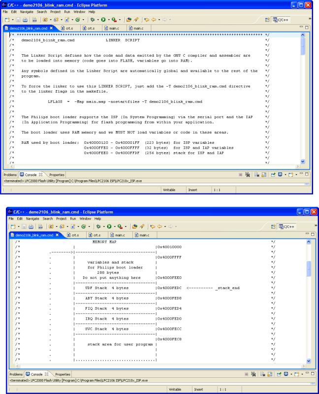
File DEMO2106_BLINK_RAM.CMD
The entire project, both code and variables, is going to be loaded into RAM. Therefore, there are a few changes in the Linker Command Script file demo2106_blink_ram.cmd.


I added quite a bit of annotation above to make it very clear how the memory (flash and ram) is organized.
Above I defined two memory areas for flash and RAM, consistent with the LPC2106 memory map. Of course, we’re going to load everything (code and variables) into RAM!

Note that I also created a global symbol, _stack_end, that is used in the startup routine to build the various stacks. The address is positioned just after the stacks and variables used by the Philips ISP Flash Utility.
Above is the final part of the Linker Command Script. Notice that everything is loaded into RAM.
You might ask, “Do we still copy the .data section initializers?” I left the copy operation intact in file CRT.S but it now essentially copies over itself (wasteful). I wanted to keep things very similar. You could delete the .data initializer copy code in crt.s to save space.
You might also ask, “Do we still clear the .bss section?” The answer is absolutely yes,
RAM memory powers on into an unknown state. We want all uninitialized variables to
be zero ar start-up. Of course, stupid programmers rely on uninitialized variables to be zero at boot-up, this is how they get into trouble with uninitialized variables (not all compilers do this automatically).
At this point, if you haven’t cleaned and built the project, do it now.
Make sure the BSL jumper is installed.
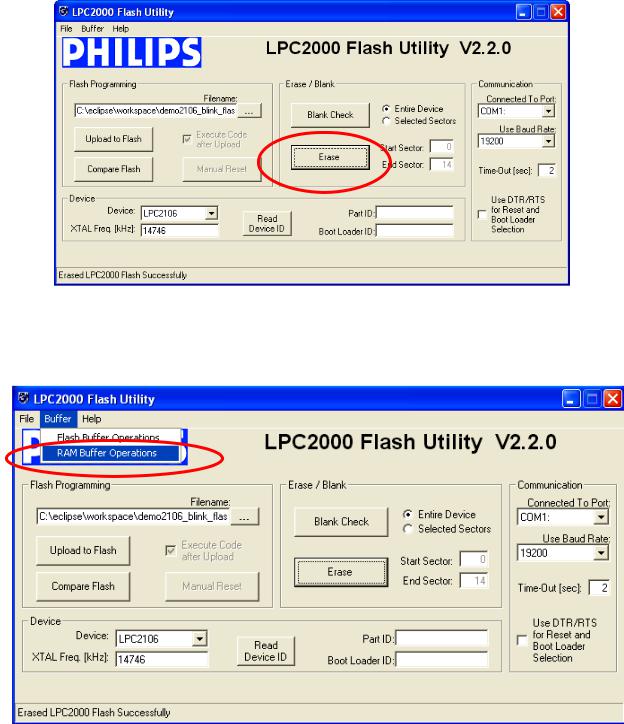
Now use the “External Tools” toolbar button to find the Philips ISP Flash Utility and start it. To make sure that we are not fooling ourselves, click on “Erase” to clear the flash memory.
Now we can be sure that the blinking LED is not the Flash application running.
Click on “Buffer – RAM Buffer Operations.”

The RAM Buffer screen now appears. Click on “Load Hex File.” This is just an operation that fetches the hex file and puts it into the Philips ISP Flash Utility.
Notice that the button titled “Run from Address” has the value &H40000200 in it. This is thanks to the ENTRY(Reset_Handler) directive in the linker command script file. The
Philips boot loader will simply load 0x40000200 into the PC register and let her rip!
When you click on the “Load Hex File” button, the following dialog will be presented.

Browse for the main.hex file in the project directory and click “Open”.
The following warning is presented. Since I advanced the location counter past the low RAM area used by Philips, it still thinks that there’s code in there. If I had elected to make the interrupt vectors a separate section, I could have avoided this warning.
It will still execute OK, of course, since the hex file has no bytes defined for the area where we advanced the program counter past the Philips ISP low RAM usage.

Now click on the “Upload to RAM” button to load the hex file into the LPC2106 RAM memory.
You will see a “progress bar” at the bottom of the screen and it will indicate that the operation has completed.