

Orbital Interaction Theory of Organic Chemistry
.pdfGROUP ORBITALS |
59 |
(b)In a planar molecule, one p orbital (pz) will always be perpendicular to the plane of the molecule and be antisymmetric w.r.t. re¯ection in the plane. The other (py) will lie in the plane and be symmetric w.r.t. re¯ection in the plane.
(c)In neutral hydrides H2X, the electron count for the heavy atoms is B 1, C 2, N 3, and O 4.
Notes on the Bent Dicoordinated Geometry
(a)The two s bonds de®ne a local plane of symmetry, assumed to be the xy plane.
The p orbital (pz) will always be perpendicular to the local plane of the molecule and be antisymmetric w.r.t. re¯ection in the plane.
(b)The sp hybrid orbital will be closest to the p orbitals for B and C and furthest for F. For O and the halogens, there will be little p character in this orbital.
(c)The spn orbital lies along the bisector of the bond angle and is symmetric w.r.t. re¯ection in the local plane of symmetry de®ned by the bonds.
(d)In neutral hydrides H2X, the electron count for the heavy atoms is B 1, C 2, N 3, and O 4.
Tricoordinated Atoms
Tricoordinated atoms may also have two distinct geometric con®gurations, planar or pyramidal. Only one valence orbital remains, and it will be a pure p orbital in the planar case, hybridized in the pyramidal case. Both con®gurations for tricoordinated atoms are depicted in Figure 3.18.
Notes
(a)In the planar geometry, the orbital is a pure p orbital and is antisymmetric w.r.t. re¯ection in the local plane of symmetry de®ned by the s bonds.
(b)In the pyramidal geometry, the orbital is an spn hybrid which lies along the local threefold axis of rotation.
(c)In neutral hydrides H3X, the electron count for the heavy atoms is B 0, C 1, and N 2.
Tetracoordinated Atoms
In many instances, the interaction of a neighboring methylene group or methyl group in¯uences the characteristics of a functional group. The appropriate group orbitals of ÐCH2 Ð and ÐCH3 are shown in Figures 3.19 and 3.20, respectively.
Figure 3.18. Group orbitals for a tricoordinated atom with planar (left) and pyramidal (right) arrangements of s bonds.

60 ORBITAL INTERACTION THEORY
Figure 3.19. Group orbitals for a tetracoordinated atom as a substituent interacting through s bonds. A methylene group is illustrated.
Group Orbitals of Methylene as a Substituent (ÐCH2 Ð)
Notes
(a)The bonding (s) and antibonding (s ) MOs form two group orbitals, one of
which is symmetric with respect to the local plane of symmetry (f1 and f3,) and the other, a p-like orbital which is antisymmetric to the local plane (f2 and f4).
Figure 3.20. Group orbitals for a tetracoordinated atom as a substituent with a tetrahedral arrangement of s bonds. A methyl group is illustrated.
ASSUMPTIONS FOR APPLICATION OF QUALITATIVE MO THEORY |
61 |
(b)Of each group, the higher energy orbital is formed from pure p orbitals at the central atom.
(c)In a molecule of Cs symmetry, the p-like orbitals (e.g., f2 and f4) will always be perpendicular to the plane of the molecule and be antisymmetric w.r.t. re¯ection
in the plane. The other (e.g., f1 and f3) will be symmetric w.r.t. re¯ection in the plane.
Methyl Group as a Substituent (ÐCH3)
Notes
(a)The bonding (s) and antibonding (s ) MOs form two group orbitals, each with
a unique axially symmetric orbital (f1 and f4,) and a pair of degenerate p-like orbitals (f2, f3 and f5, f6)
(b)Of each group, the higher energy orbitals are formed from pure p orbitals at the central atom.
(c)In a molecule with Cs symmetry, one of the degenerate bonding and antibonding orbitals (e.g., f2 and f5) will always be perpendicular to the plane of the molecule and be antisymmetric w.r.t. re¯ection in the plane. The other (e.g., f3 and f6) will lie in the plane and be symmetric w.r.t. re¯ection in the plane.
ASSUMPTIONS FOR APPLICATION OF QUALITATIVE MO THEORY
Gimarc has speci®ed a set of rules for the application of qualitative MO theory [73], particularly for the determination of molecular structures and conformations, following the pioneering work of Walsh [74]. These are repeated here:
1.Electrons in molecules are completely delocalized and move in molecular orbitals which extend over the entire molecular framework.
2.For properties which can be explained by qualitative MO theory, only the valence electrons need be considered.
3.Satisfactory MOs can be formed from linear combinations of atomic orbitals (LCAO). This is the well-known LCAO±MO approximation already discussed in Chapter 2.
4.The atoms which form the molecules of a particular series or class contribute the same kinds of valence AOs from which MOs can be constructed. Therefore the MOs for each series or type of molecular framework must be qualitatively similar, and individual molecules di¨er primarily in the number of valence electrons occupying the common MO system.
5.The total energy of the molecule is the sum of the orbital energies of the valence electrons, or, more accurately, changes in the total energy parallel those in the orbital energy sum. Peyerimho¨ and co-workers [75] have shown that this assumption results from a fortuitous cancellation of energy terms.
6.No explicit consideration of electron±electron or nuclear±nuclear repulsions are included in this simple model.
7.Molecular orbitals must be either symmetric or antisymmetric with respect to the symmetry operations of the molecule. These symmetry restrictions severely limit

62 ORBITAL INTERACTION THEORY
the number and kinds of AOs that combine in a particular MO. This makes the job of forming the MOs even easier, since most small molecules have high symmetry. To use qualitative MO theory, the only part of group theory necessary is a knowledge of symmetry classi®cations (see Chapter 1).
8.From properties of AOs available on component atoms it is possible to draw pictures of what the MOs must be like and to establish the approximate order of energies without calculations.
9.Changes in molecular shape which increase the in-phase overlap between two or more AOs in a MO tend to lower the energy of that MO. Conversely, changes in shape which decrease in-phase overlap or increase out-of-phase overlap among AOs in a MO tend to raise the energy of the MO. This can be called the overlap rule.
10.No a priori assumptions about orbital hybridization are needed. As we shall see, however, simple application of the idea of hybridization will come in handy from time to time.
EXAMPLE: CARBONYL GROUP
The carbonyl group is an important functional group in organic chemistry. It undergoes both nucleophilic and electrophilic additions and has a profound in¯uence on the properties of neighboring groups. In this book, a separate chapter (Chapter 8) is dedicated to it. At this point we will develop the complete bonding scheme for the carbonyl group using orbital interaction diagrams:
The example will serve to illustrate application of the principles for construction of orbital interaction diagrams and also to illustrate the wealth of information which may be deduced on the basis of the diagrams. Since we are describing the existing bonding of a molecule, we imagine it to originate from the interaction of fragment orbitals. In this situation, some or all of the orbital overlaps will be large and the principles of strong interactions apply.
CONSTRUCTION OF INTERACTION DIAGRAM
We begin the construction of the diagrams by deciding on the groups which are interacting. If we were interested in only the p bonds, we would note that the p bond is between a tricoordinated atom (the carbon atom) and a monocoordinated atom (the oxygen atom). However, we will not assume prior bonding between the carbon atom and the oxygen atom. Therefore, we will use a bent dicoordinated atom as one of our groups and a zero-coordinated atom for the other. Refer to Figure 3.21 as the development of the interaction diagram progresses. We must next decide on the placement of the groups relative to each other. Since we are attempting to understand the bonding in the carbonyl group, we will position the dicoordinated C atom and the zero-coordinated O atom in the positions and orientations that they occupy in the ®nished carbonyl group, using our prior knowledge of the structure of the carbonyl group. We also chose to display

CONSTRUCTION OF INTERACTION DIAGRAM |
63 |
Figure 3.21. Interaction diagram for the carbonyl group.
the planar structure as lying in the plane of the paper (the xy plane), the most obvious choice. We know that the dicoordinated atom has two valence orbitals, a p orbital perpendicular to the plane of the bent s bonds (a pz orbital) and an spn hybrid orbital oriented along the bisector of the angle made by the s bonds (the x direction) and polarized away from them (Figure 3.17). The zero-coordinated atom has four valence orbitals, two p orbitals oriented perpendicular to the direction of the incipient s bond (py and pz), and two spn hybrids oriented along the incipient s bond but polarized in opposite directions (Figure 3.14).
We must next decide on the placement of these orbitals relative to each other on the same energy scale. We have no way of doing this precisely, but we note that oxygen is substantially more electronegative than C (Table A.2 in Appendix A), and so we place the oxygen group orbitals to lower energy than the carbon group orbitals. The placement
64 ORBITAL INTERACTION THEORY
on the energy scale (the vertical direction is shown by short bold horizontal lines). The positioning in space (i.e., left or right side) should be consistent with the orientation of the two groups relative to each other in space. In the present case, we have chosen oxygen to be to the right.
Our choice of orientation of the s framework (as determined by the bent coordination of the dicoordinated C atom and the intended CÐO s bond) in the xy plane (the plane of the page) determines the orientation of the valence group orbitals. These should be drawn on the diagram beside the appropriate energy levels, each superimposed on a separate sketch of the s framework, and labelled fully, as shown in Figure 3.21. All of the orbitals should be drawn about the same size, since their ``weights'' are equal before the interaction (their coe½cients are 1).
Next we must decide which orbitals of the right and left sides interact and, approximately or relatively, how strong the interaction is. Consider ®rst the spn hybrid orbital on the left-hand side. This will interact only with the spn hybrid orbital on the righthand side which is pointed toward it (toward the left). The interaction is of s type, and because the two orbitals overlap strongly, a large amount of stabilization …DeL† and destabilization …DeU† ensue. Make DeL at least as large as the energy separation of the orbitals on the leftand right-hand sides of your diagram (Figure 3.21), and draw a short bold horizontal line at this position midway between the left and right energy level lines. Make DeU even larger (by about 20%) and draw it in place the same way. Connect these four levels by thin straight lines (shown as dashed lines in Figure 3.21). The molecular orbitals, fL and fU, which result from the interaction must also be drawn. These should be positioned near the lines denoting their energies and positioned on the s framework in a manner consistent with the uninteracted orbitals. The nature of fL and fU is determined by the algebra of the ®rst part of this chapter. The lower orbital, which we may label sCO, consists of the two orbitals interacting in phase, with a larger contribution from the oxygen side and a smaller one from the carbon side. The actual choice of phases does not matter, only that the phases where the orbitals overlap the most are the same. The phases are best shown by shading. The sizes of the orbitals drawn should be proportional to the coe½cients expected for them. We do not know the exact values, but we do know that the coe½cients will be less than 1 as a result of the interaction, since the MO is now made up of two orbitals. Most importantly, we know that the MOs will be polarized. The lower orbital, sCO, is polarized toward O. The size of the contributing oxygen orbital should be drawn a little smaller than the uninteracted oxygen orbital, and the size of the in-phase carbon orbital smaller still. The upper orbital, sCO, is polarized toward C. The size of the contributing carbon orbital should be drawn a little smaller than the uninteracted carbon orbital, and the size of the out-of-phase oxygen orbital smaller still.
Consider now the pz orbital on the left. It can overlap and therefore interact, only with one orbital on the right, the pz orbital of oxygen. The interaction is of p type. Because of the smaller overlap, the p-type interaction is intrinsically smaller than a s-type interaction between similar orbitals. This must be borne in mind in positioning the p and p orbitals on the diagram relative to the already placed s orbitals. As a rough guide, you may take DeL for the p-type interaction to be about one-half of DeL for the s-type interaction, similarly for the energies of destabilization. Having decided on the positions (Figure 3.21), draw the levels in, and label them pCO and pCO, and draw the connecting straight lines. Sketch in the MOs, bearing in mind the principles stated above in connection with the sCO and sCO orbitals. The only additional consideration is that the polarization of the p and p orbitals should be a little greater than of the sCO and sCO orbitals since the p-type overlap is smaller.

INTERPRETATION OF THE INTERACTION DIAGRAM |
65 |
Two orbitals of the oxygen atom have not been involved in the interaction so far, the py orbital and the other spn hybrid. These are transferred to the middle of the diagram unchanged in energy or shape, although, for completeness, they should be redrawn in place; they are nonbonding orbitals of the carbonyl group, nO0 and nO.
Lastly, one must occupy the MOs with the correct number of electrons. A neutral dicoordinated carbon atom has two valence electrons and a neutral uncoordinated oxygen atom has six, for a total of eight. Place electrons into the MOs two at a time. The HOMO is seen to be the higher nonbonding MO, nO, and the LUMO is pCO.
INTERPRETATION OF THE INTERACTION DIAGRAM
Having carefully constructed the interaction diagram for the carbonyl group in Figure 3.21, we must now interpret it. We ®rst make note of the frontier orbitals.
Frontier Orbitals HOMO and LUMO. The HOMO nO is a nonbonding MO strongly localized to oxygen. It is predominantly a 2p orbital lying in the plane of the molecule. Within the (local) C2v point group, it transforms as the b2 irreducible representation. The LUMO pCO is a p antibonding orbital strongly polarized toward the carbon atom, and relatively low in energy, at least compared to the position of the pCC orbital of ethylene. We know this because the CÐO 2p±2p p-type interaction matrix element hAB should be similar in magnitude to the interaction between 2p of carbon atoms, but the oxygen and carbon 2p orbital energies are quite di¨erent, leading to a smaller DeU for pCO. Within the (local) C2v point group, it transforms as the b1 irreducible representation.
Bonding. Of the four occupied MOs, two are bonding and two are nonbonding, resulting in a net bond order of 2, that is, a double bond. Both the s and p bonds are polarized toward oxygen, the p more than the s because of the smaller intrinsic overlap (p-type overlap is smaller than s-type overlap).
Dipole Moment. A large bond dipole moment is expected, with the negative end at oxygen and the positive end at carbon.
Geometry. The combination of s and p bonds forces coplanarity of the oxygen atom, the carbon atom, and the other two atoms attached to the carbon atom.
Ionization. One cannot say anything about the magnitude of the ionization potential from just one interaction diagram. However, we can say with con®dence that the lowest energy (strictly speaking, the ground electronic state of the) molecular ion, M‡, would correspond to a radical cation localized to the oxygen atom. With this foreknowledge, one would expect to ®nd mass spectral fragments which arise from the McLa¨erty rearrangement and from rupture of the bond a to the carbonyl group:
66 ORBITAL INTERACTION THEORY
UV Spectrum. The lowest energy electronic transition (HOMO±LUMO) is nO ±pCO, leading to the np state, which has A2 symmetry in the local C2v point group. The transition to this state is symmetry forbidden (it is quadrupole allowed but dipole forbidden) and will be expected to be weak.
Photochemistry. One might deduce that since the lowest electronic transition corresponds to transfer of an electron from an oxygen atom to a carbon atom, the np state should have substantial diradical character and should react also by a McLa¨erty-type rearrangement or a cleavage, as in the mass spectrometer. This is indeed the case. The photochemical a cleavage is called the Norrish type I reaction, and the rearrangement is called the Norrish type II reaction. Both are discussed in Chapter 15.
CHEMICAL REACTIVITY
To make a statement about the chemical reactivity of a substance, one must imagine its orbitals interacting with those of a second reagent. Since two reagents are involved, the initial orbital overlaps are small and the interactions will be governed by the principles of weak interactions. In the ®rst instance, only the frontier orbitals, the HOMOs and the LUMOs, need be considered. To probe the basicity or nucleophilicity, the interaction of a proton (empty s orbital) with the HOMO is su½cient. For checking acidity in the Lewis sense, the interaction of the LUMO with the HOMO of a reference base, say the nonbonded spn orbital of ammonia, is appropriate. In general, the orbital interaction diagram for the interaction of two reagents is only appropriate for the initially formed van der Waals or hydrogen-bonded complex. It shows the HOMO±LUMO orbital interactions which are maximized and the HOMO±HOMO interactions which are minimized as the two reagents approach each other in the energetically most favorable way. The trajectory of approach and the orbitals involved will almost always imply the product, but the interaction diagram will not show the bonding in the product. If the orbital donating or accepting electrons is nonbonding, the newly formed bond will not greatly perturb the other bonds in the fragment. However, if a s or p bond acts as an electron donor, that bond is weakened since it loses electrons and, in a chemical reaction, will be broken altogether. Similarly, if, as is usually the case, an empty antibonding orbital is the electron acceptor, the corresponding bond is also weakened, and if the reaction goes all the way, the bond is completely broken. The bonding of the products of a chemical reaction must be deduced with separate interaction diagrams since these are in the regime of strong interactions. In short, the weak-interaction regime and the strong-interaction regime must not be mixed in the same diagram. This can be accomplished by means of orbital correlation diagrams, as seen in Chapter 14.
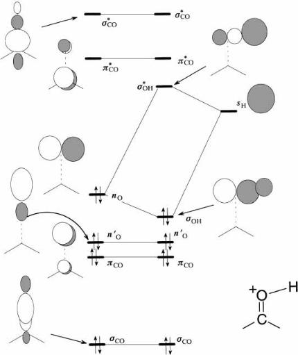
Basicity or Nucleophilicity. Figure 3.22 shows the interaction diagram for the initial interaction between the carbonyl group and a proton (which we take to be a typical Lewic acid). This is constructed along the same principles as for the carbonyl group itself. On the left-hand side we place some or all of the orbitals derived for the carbonyl group in Figure 3.21. As stated above, only the HOMO will be required, but let us choose all of them to make the point. On the right hand side, we place the single 1s orbital of the hydrogen (proton), sH. Since H is slightly less electronegative than C, sH should be a little above the energy level of the 2pC orbital of the CH2 group prior to interaction (see Figure 3.21). We have six carbonyl group orbitals on the left and a single
CHEMICAL REACTIVITY |
67 |
Figure 3.22. Interaction diagram for the carbonyl group with a proton (the electrostatic e¨ect of the positive charge is ignored).
sH orbital on the right. What are the possible interactions between the leftand righthand sides? Because the proton is a separate free-roaming species, the sH orbital is not precluded by symmetry from interacting with any of the orbitals of the carbonyl group since it can always approach from a direction that avoids nodal surfaces. The most probable direction is the one which leads to the greatest gain in energy. Since the sH orbital is empty, only the occupied orbitals of the carbonyl group need be considered, and it is usually safe to focus only on the HOMO since this has the smallest energy separation with an empty orbital, the LUMO sH. Since the HOMO nO is the 2pO, the greatest s-type overlap is from a direction along the axis of the p orbital, namely in the plane of the carbonyl group, approaching the O atom from either side perpendicular to the CÐO

68 ORBITAL INTERACTION THEORY
bond. Thus, attachment of a proton or other Lewis acid would occur at the oxygen atom, in the plane of the carbonyl group, and more or less perpendicular to the CÐO bond. In Figure 3.22, we show the interaction of the nO and sH orbitals in the most natural geometry, with the newly formed s bond horizontally disposed. Notice that we have reoriented the molecular framework and all of the orbitals into the same orientation from the one in Figure 3.21. This reorientation does not a¨ect the orbital energies. Notice that the line of approach for the HOMO±LUMO interaction brings the proton in approximately along the nodal surfaces of all of the other orbitals, so in the ®rst instance all other possible interactions will be small and can be ignored. To make this point, Figure 3.22 is far more cluttered than it needed to be since only the orbitals connected by the interaction lines needed to be shown.
This diagram shows only the initial interaction as would be suitable for formation of a hydrogen bond. If the proton were to become attached, the sOH orbital would be much lower in energy and the sOH much higher. Since the donor orbital is nonbonding, addition of the Lewis acid to the oxygen is not accompanied by loss of either the s or p bond. In this ®gure, we have ignored the e¨ect of the charge. We will see in Chapters 5 and 8 that the net charge does have a dramatic e¨ect on the remaining orbitals.
We can also crudely estimate the basicity of the carbonyl oxygen atom. Since the HOMO is strongly localized to the oxygen atom (the coe½cient of 2 pO is close to 1), and the oxygen atom is monocoordinated but uncharged, one should expect the Lowry± Bronsted basicity to be less than that of alkoxides, which are monocoordinated but charged.
Acidity or Electrophilicity. The LUMO is a p-type orbital polarized toward the carbon atom (the coe½cient of 2pC is larger than the coe½cient of 2pO). The LUMO is also relatively low in energy. The low energy and large coe½cient at carbon both suggest that the carbonyl group should be reactive as a Lewis acid or electrophile and that addition of nucleophiles (Lewis bases) would occur at the carbon atom and from a direction approximately perpendicular to the plane of the carbonyl group. Figure 3.23 shows another way of applying orbital interaction theory. Orbital interaction arguments are applied to deduce trajectories of attack of a nucleophile to the carbonyl group by showing the HOMO of the nucleophile (ammonia in this case) and the LUMO of the carbonyl. The best approach, which avoids both nodal surfaces of the pCO orbital (the nodal plane
Figure 3.23. Trajectory of nucleophilic attack on a carbonyl group deduced from orbital interaction theory.