

CHAPTER
ADC and DAC
3
Most of the signals directly encountered in science and engineering are continuous: light intensity that changes with distance; voltage that varies over time; a chemical reaction rate that depends on temperature, etc. Analog-to-Digital Conversion (ADC) and Digital-to-Analog Conversion (DAC) are the processes that allow digital computers to interact with these everyday signals. Digital information is different from its continuous counterpart in two important respects: it is sampled, and it is quantized. Both of these restrict how much information a digital signal can contain. This chapter is about information management: understanding what information you need to retain, and what information you can afford to lose. In turn, this dictates the selection of the sampling frequency, number of bits, and type of analog filtering needed for converting between the analog and digital realms.
Quantization
First, a bit of trivia. As you know, it is a digital computer, not a digit computer. The information processed is called digital data, not digit data. Why then, is analog-to-digital conversion generally called: digitize and digitization, rather than digitalize and digitalization? The answer is nothing you would expect. When electronics got around to inventing digital techniques, the preferred names had already been snatched up by the medical community nearly a century before. Digitalize and digitalization mean to administer the heart stimulant digitalis.
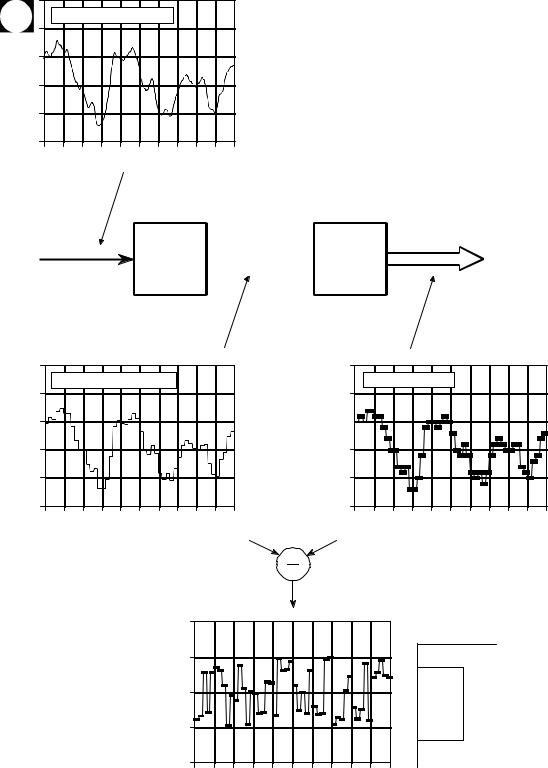
Figure 3-1 shows the electronic waveforms of a typical analog-to-digital conversion. Figure (a) is the analog signal to be digitized. As shown by the labels on the graph, this signal is a voltage that varies over time. To make the numbers easier, we will assume that the voltage can vary from 0 to 4.095 volts, corresponding to the digital numbers between 0 and 4095 that will be produced by a 12 bit digitizer. Notice that the block diagram is broken into two sections, the sample-and-hold (S/H), and the analog-to-digital converter (ADC). As you probably learned in electronics classes, the sample-and-hold is required to keep the voltage entering the ADC constant while the
35

36 |
The Scientist and Engineer's Guide to Digital Signal Processing |
conversion is taking place. However, this is not the reason it is shown here; breaking the digitization into these two stages is an important theoretical model for understanding digitization. The fact that it happens to look like common electronics is just a fortunate bonus.
As shown by the difference between (a) and (b), the output of the sample-and- hold is allowed to change only at periodic intervals, at which time it is made identical to the instantaneous value of the input signal. Changes in the input signal that occur between these sampling times are completely ignored. That is, sampling converts the independent variable (time in this example) from continuous to discrete.
As shown by the difference between (b) and (c), the ADC produces an integer value between 0 and 4095 for each of the flat regions in (b). This introduces an error, since each plateau can be any voltage between 0 and 4.095 volts. For example, both 2.56000 volts and 2.56001 volts will be converted into digital number 2560. In other words, quantization converts the dependent variable (voltage in this example) from continuous to discrete.
Notice that we carefully avoid comparing (a) and (c), as this would lump the sampling and quantization together. It is important that we analyze them separately because they degrade the signal in different ways, as well as being controlled by different parameters in the electronics. There are also cases where one is used without the other. For instance, sampling without quantization is used in switched capacitor filters.
First we will look at the effects of quantization. Any one sample in the digitized signal can have a maximum error of ±½ LSB (Least Significant Bit, jargon for the distance between adjacent quantization levels). Figure (d) shows the quantization error for this particular example, found by subtracting
(b) from (c), with the appropriate conversions. In other words, the digital output (c), is equivalent to the continuous input (b), plus a quantization error
(d). An important feature of this analysis is that the quantization error appears very much like random noise.
This sets the stage for an important model of quantization error. In most cases, quantization results in nothing more than the addition of a specific amount of random noise to the signal. The additive noise is uniformly distributed between ±½ LSB, has a mean of zero, and a standard deviation of 1/ 12 LSB (-0.29 LSB). For example, passing an analog signal through an 8 bit digitizer adds an rms noise of: 0.29 /256 , or about 1/900 of the full scale value. A 12 bit conversion adds a noise of: 0.29 /4096 . 1 /14,000 , while a 16 bit conversion adds: 0.29 /65536 . 1 /227,000 . Since quantization error is a random noise, the number of bits determines the precision of the data. For example, you might make the statement: "We increased the precision of the measurement from 8 to 12 bits."
This model is extremely powerful, because the random noise generated by quantization will simply add to whatever noise is already present in the
Chapter 3- ADC and DAC |
37 |
|
3.025 |
|
|
|
|
|
|
|
|
|
|
|
|
a. Original analog signal |
|
|
|
|
|||||
volts) |
3.020 |
|
|
|
|
|
|
|
|
|
|
3.015 |
|
|
|
|
|
|
|
|
|
|
|
(in |
|
|
|
|
|
|
|
|
|
|
|
|
|
|
|
|
|
|
|
|
|
|
|
Amplitude |
3.010 |
|
|
|
|
|
|
|
|
|
|
|
|
|
|
|
|
|
|
|
|
|
|
|
3.005 |
|
|
|
|
|
|
|
|
|
|
|
3.000 |
|
|
|
|
|
|
|
|
|
|
|
0 |
5 |
10 |
15 |
20 |
25 |
30 |
35 |
40 |
45 |
50 |
|
|
|
|
|
|
Time |
|
|
|
|
|
FIGURE 3-1
Waveforms illustrating the digitization process. The conversion is broken into two stages to allow the effects of sampling to be separated from the effects of quantization. The first stage is the sample-and-hold (S/H), where the only information retained is the instantaneous value of the signal when the periodic sampling takes place. In the second stage, the ADC converts the voltage to the nearest integer number. This results in each sample in the digitized signal having an error of up to ±½ LSB, as shown in (d). As a result, quantization can usually be modeled as simply adding noise to the signal.
analog |
digital |
input |
output |
S/H  ADC
ADC
Amplitude (in volts)
3.025 |
|
|
|
|
|
|
|
|
|
|
|
b. Sampled analog signal |
|
|
|
|
|||||
3.020 |
|
|
|
|
|
|
|
|
|
|
3.015 |
|
|
|
|
|
|
|
|
|
|
3.010 |
|
|
|
|
|
|
|
|
|
|
3.005 |
|
|
|
|
|
|
|
|
|
|
3.000 |
|
|
|
|
|
|
|
|
|
|
0 |
5 |
10 |
15 |
20 |
25 |
30 |
35 |
40 |
45 |
50 |
|
|
|
|
|
Time |
|
|
|
|
|
Digital number
3025
c. Digitized signal
3020
3015 

3010
3005
3000
0 |
5 |
10 |
15 |
20 |
25 |
30 |
35 |
40 |
45 |
50 |
Sample number
Error (in LSBs)
1.0
d. Quantization error |
0.5
0.0
-0.5
-1.0
0 |
5 |
10 |
15 |
20 |
25 |
30 |
35 |
40 |
45 |
50 |
Sample number

38 |
The Scientist and Engineer's Guide to Digital Signal Processing |
analog signal. For example, imagine an analog signal with a maximum amplitude of 1.0 volt, and a random noise of 1.0 millivolt rms. Digitizing this signal to 8 bits results in 1.0 volt becoming digital number 255, and 1.0 millivolt becoming 0.255 LSB. As discussed in the last chapter, random noise signals are combined by adding their variances. That is, the signals are added in quadrature:  A 2 %B 2 ' C . The total noise on the digitized signal is therefore given by:
  0.2552 % 0.292 ' 0.386 LSB. This is an increase of about 50% over the noise already in the analog signal. Digitizing this same signal to 12 bits would produce virtually no increase in the noise, and nothing would be lost due to quantization. When faced with the decision of how many bits are needed in a system, ask two questions: (1) How much noise is already present in the analog signal? (2) How much noise can be tolerated in the digital signal?
When isn't this model of quantization valid? Only when the quantization error cannot be treated as random. The only common occurrence of this is when the analog signal remains at about the same value for many consecutive samples, as is illustrated in Fig. 3-2a. The output remains stuck on the same digital number for many samples in a row, even though the analog signal may be changing up to ±½ LSB. Instead of being an additive random noise, the quantization error now looks like a thresholding effect or weird distortion.
Dithering is a common technique for improving the digitization of these slowly varying signals. As shown in Fig. 3-2b, a small amount of random noise is added to the analog signal. In this example, the added noise is normally distributed with a standard deviation of 2/3 LSB, resulting in a peak- to-peak amplitude of about 3 LSB. Figure (c) shows how the addition of this dithering noise has affected the digitized signal. Even when the original analog signal is changing by less than ±½ LSB, the added noise causes the digital output to randomly toggle between adjacent levels.
To understand how this improves the situation, imagine that the input signal is a constant analog voltage of 3.0001 volts, making it one-tenth of the way between the digital levels 3000 and 3001. Without dithering, taking 10,000 samples of this signal would produce 10,000 identical numbers, all having the value of 3000. Next, repeat the thought experiment with a small amount of dithering noise added. The 10,000 values will now oscillate between two (or more) levels, with about 90% having a value of 3000, and 10% having a value of 3001. Taking the average of all 10,000 values results in something close to 3000.1. Even though a single measurement has the inherent ±½ LSB limitation, the statistics of a large number of the samples can do much better. This is quite a strange situation: adding noise provides more information.
Circuits for dithering can be quite sophisticated, such as using a computer to generate random numbers, and then passing them through a DAC to produce the added noise. After digitization, the computer can subtract