

Aggarwal V.A self-tuning analog PID controller
.pdfA Self-Tuning Analog Proportional-Integral-Derivative (PID) Controller
Varun Aggarwal, Meng Mao and Una-May O’Reilly
Adaptive Hardware Group
Computer Science and Artificial Intelligence Lab
Massachusetts Institute of Technology
varun ag@csail.mit.edu, mao@mit.edu and unamay@csail.mit.edu
Abstract
We present a framework for a low power self-tuning analog proportional-integral-derivative controller. By using a model-free tuning method, it overcomes problems associated with reconfigurable analog arrays. In comparison to a self-tuning digital PID controller, it combines the advantages of low power, no quantization noise, high bandwidth and high speed. Our prototype hardware uses a commercially available field programmable analog array and Particle Swarm Optimization as the tuning method. We developed a scheme to correct the variance in measurement. We show that a self-tuned controller can outperform a handtuned solution and demonstrate adaptability to plant drift.
method [16, 3, 5]. A comprehensive review of these methods is given in [14].
The hardware used for PID controllers has evolved from pneumatic configurations in the 1940’s, electrical devices in the 1960’s to the current microprocessor-based controller technology. Observation indicates that analog electronic PID controllers have never been in widespread use. This is despite the fact that most processes that are controlled are analog. Instead of a strictly analog controller, digital signal processor (DSP) based PID controllers are used. These employ analog-to-digital converters (ADCs) at their input and digital-to-analog converters (DACs) at their output to interface with the plant. An analog controller combines several advantages over a digital controller which can be summarized as follows.
1.An analog system provides larger bandwidth, higher speed and eliminates quantization noise.
1 Introduction
Proportional-Integral-Derivative (PID) control has been used successfully for regulating processes in industry for more than 60 years. Today, digital self-tuning PID controllers are ubiquitous in the industry. These controllers automatically set gain values (i.e. parameters) according to the process (alternatively, plant) and may optionally require inputs from a human designer.
The parameter settings of a PID controller for optimal control of a plant depend on the plant’s behavior. Therefore, information about the plant is required to tune the PID controller. The tuning methods fall into two broad categories: online model-free methods and methods that build a model of the plant. The former tune the PID controller in loop with the given plant using an optimization algorithm such as steepest descent or Newton’s method to minimize some cost function [12, 14], for instance, error between the input and output . The second approach builds a model of the plant and accordingly decides the parameters of the controller by using a deterministic approach or an optimization
2.An analog controller must use a reconfigurable analog array instead of a DSP. The power consumption of a DSP halves every 18 months, as postulated by Gene’s Law [7]. It is shown in [11], that using a reconfigurable analog array can decrease power consumed by five orders of magnitude as compared to a DSP, implying by Gene’s Law a 20 year leap in power reduction.
3.High performance data converters are required for a DSP-based controller. The performance of the converter in terms of its speed, conversion precision and noise greatly influences the fidelity of the controller.
An analog controller eliminates the need for ADCs and DACs, thus saving power, space and cost. As the power of the DSP is reduced, the power consumption of the data-converters will dominate, thus their elimination is very advantageous.
Besides conventional considerations, reduced power consumption would also be very useful for controllers used on spaceships, on mobile, autonomous robots, or similar applications.

Why aren’t analog PID controllers designed and used despite these advantages? The answer to this question is the unavailability of electronically-reconfigurable, reliable and precise analog arrays. The controller must be reconfigurable because the PID parameters have to be tuned according to the plant. The precision and range of the reconfigurable system must provide sufficient flexibility to implement PID control for a variety of plants. The difference between the the actual and predicted behavior of the array is another problem.
Electronically reconfigurable analog devices called Field Programmable Analog Arrays (FPAA) are a fairly recent phenomenon as compared to their digital counterparts called Field Programmable Gate Arrays (FPGAs) which are widely used in industry and academia. FPAAs started appearing in literature in the late 1980’s and the first commercial offering was as recent as 1996 [17]. Due to the nontrivial effect of parasitics and increased die area, FPAAs are still not in widespread use nor are they an active research area. However, the results of this contribution suggest that the current designs of FPAAs are mature enough to implement a self-tuning analog PID controller. Anadigm already offers a manually tunable PID control block on their FPAA and other analog PID controllers are also available [13].
In this paper, we propose a paradigm for the design of a self-tuning analog PID controller. In Section 2 we discuss how this framework circumvents the limitation associated with analog PID controllers and how it compares with a DSP microprocessor-based controller. In Section 3 we describe in detail our working prototype. In Section 4 we experimentally evaluate our prototype. Finally, in Section 5, we summarize and indicate future directions of work.
2Framework for a Self-Tuning Analog PID Controller
A mixed analog-digital control system is shown in Figure 1. It uses a DSP-based controller together with in-loop data converters. When the system is self-tunable, it employs a variety of methods and includes additional components such as another microprocessor and data converters.
Our framework for a self-tuning analog PID controller is shown in Figure 2. It uses a reconfigurable analog block as the controller and a microprocessor to run the tuning algorithm. The switches are used to put the system into control or tuning mode. In control mode, the FPAA takes the user input and controls the plant accordingly. In the self-tuning mode, the input is generated by a function generator controlled by the microprocessor. The system uses a model-free method, i.e. on the microprocessor it executes an optimization algorithm that minimizes a cost function defined on the characteristics of the closed-loop system. To get data for optimization, a 2-channel ADC is used to digitize and send
the input and output signal to the processor.
OPTIONAL
Microprocessor
running
Tuning Algorithm
 Strobe
ADC |
REF sig. |
(cheap) |
Generator |
Controller + Tuner (Optional)
|
|
e(t) |
ADC |
DSP |
DAC |
Output |
Input |
- |
|
Plant |
|||
|
(precise) |
Processor |
(precise) |
|||
|
|
|
|
Figure 1. Conventional self-tuning DSPbased PID controller model.
REF SIGNAL GEN
Microprocessor running
tuning algorithm
 Strobe
ADC |
REF sig. |
(cheap) |
Generator |
Input |
- e(t) |
Reconfigurable |
Output |
|
Plant |
||||
Analog PID |
||||
|
|
Controller |
|
Figure 2. Proposed self-tuning analog PID controller model.
The model for this self-tuning analog PID has several advantages over the digital PID system. As already discussed, the reconfigurable analog block is much more power efficient than the DSP controller. Unlike digital PID controllers, it does not need fast and accurate (thus, high power) in-loop data converters. The only ADC required for the self-tuning analog PID is for data collection for automatic tuning (outside the control loop). It can be slow and low precision (hence, low power). Once the tuning is done, the ADC and microprocessor are shut down so they do not consume power during the control mode. The analog circuit combines the traditional advantage of larger bandwidth, no quantization noise and higher speed. Figure 3 shows how the cost function can be implemented as an analog circuit (illustrated for squared error, can also use the error signal, e(t), directly) to further relax the speed requirements on an ADC and eliminate one of them.
In tuning methods that model the plant and calculate parameter values accordingly, a potential problem is that the FPAA can not realize the calculated values or does so inaccurately. However, in model-free methods, optimization proceeds by directly instantiating test points in-situ on the FPAA and measuring cost function value. Any inaccuracy

REF SIGNAL GEN
Microprocessor
running
Tuning Algorithm
|
|
|
|
|
Strobe |
|
|
|
|
|
|
||||
|
|
ADC |
|
|
|
|
|
|
|||||||
|
|
(cheap) |
|
REF sig. |
|
|
|
|
|
|
|
||||
|
|
|
|
|
Generator |
|
|
|
|
|
|
|
|||
|
|
|
|
|
|
|
|
|
|
|
|
|
|
|
|
Cost |
|
∫x2dx |
|
|
|
|
|
|
|
|
|
|
|
|
|
Function |
|
|
|
|
|
|
|
|
|
|
|
|
|
|
|
|
- |
|
|
|
|
|
|
|
|
|
|
|
|
Output |
|
|
|
|
|
- |
e(t) |
Reconfigurable |
|
Plant |
|
||||||
|
|
|
|
|
|
|
|||||||||
Input |
|
|
|
|
Analog PID |
|
|
|
|||||||
|
|
|
|
|
|
|
|
|
|
Controller |
|
|
|
|
|
|
|
|
|
|
|
|
|
|
|
|
|
|
|
||
|
|
|
|
|
|
|
|
|
|
|
|
|
|
|
|
|
|
|
|
|
|
|
|
|
|
|
|
|
|
|
|
|
|
|
|
|
|
|
|
|
|
|
|
|
|
|
|
Figure 3. Self-tuning analog PID controller model with cost function integrated into analog hardware.
in FPAA calibration is implicit in the cost function evaluation. This eliminates calibration and potentially unachievable component value goals for the FPAA. Search proceeds within the available range and precision. The PID circuit on the Anadigm FPAA has a wide range for parameters (see Section 3). Other FPAAs could support different ranges, and a custom analog PID chip can even be designed to accommodate a large range. In SIM960 [13] an industrial analog PID controller, the ranges are as high as 10−1 to 103 (proportional gain), 10−1s−1 to 105s−1 (integral gain) and 10−7s to 1s (derivative gain).
In terms of related work, researchers primarily from the evolvable hardware community have designed self-tuning and fault tolerant analog controllers. In [9], an evolutionary algorithm is used to invent a new controller topology on an Field Programmable Transistor Array (FPTA). It uses fewer components than a PI controller but results in worse performance. In [10], the plant is modeled and subsequently a controller topology for it is evolved on the FPTA. The FPTA platform is not reliable due to performance drifts with time [19]. Other approaches include evolution of fuzzy logic controller topologies on an FPAA [6] and tuning of an artificial neural network on an FPAA to control robotic motion [4]. The controller in [4] is not self-tuning: a human evaluates the objective and must intervene when the mobile robot falls down during its tuning. None of the approaches propose or build a self-tuning robust analog PID controller.
This summarizes our framework for a self-tuning analog PID controller. This framework has several advantages over the digital PID controller and also solves the problems associated with an FPAA. It may be extended to other tuning methods and controlling strategies. These strategies such as a Smith controller or fuzzy controllers have matured in the domain of digital PID controllers.
3 Our Prototype
circuit could be automatically designed and sized by an intelligent algorithm running on a PC. Figure 4 illustrates the use of GRACE as a reconfigurable controller for a plant. The FPAA and the plant form a closed loop system. The algorithm runs on a PC to tune the controller given a cost function. It generates a reference signal which is converted to an analog signal by an ADC (part of the Data Acquisition Card (DAQ)) and sent as the input to the closed loop system. The reference signal and the output of the closed loop system are digitized and received by the algorithm. The algorithm optimizes a cost function defined on these two signals. It reconfigures the FPAA and re-evaluates the cost function to facilitate the optimization process.
serial |
|
|
FPAA |
|
|
Controller |
SRAM |
PLANT |
|||
Evolutionary |
Configuration |
||||
|
|||||
|
|
|
|||
Algorithm |
|
|
|
|
|
DAQ |
Vreft |
- |
Configured |
Vin |
|
|
|
Vout |
Controller |
|
|
|
|
|
|
||
Figure 4. The GRACE System
GRACE uses the Anadigm AN221E04 FPAA, which uses switched capacitor technology to implement analog circuits. The FPAA can instantiate different analog blocks such as differentiators, integrators, summers and difference amplifiers which can be connected to form different circuits. The parameter values such as differentiation or integration constant and amplification gains are also programmable. This chip supports I/O range of 0 to 3.8V in differential mode. EHW@CSAIL
On the AN221E04, we instantiated a PID controller (with an offset corrector) whose topology is shown in Figure 5.
|
|
B2 |
|
|
|
REF |
B1 |
∫ |
|
|
|
|
|
B4 |
|
||
|
+ |
E(s) |
+ |
|
|
|
SUMDIFF |
|
|
|
|
FEEDBACK |
- |
|
+ |
|
OUTPUT |
|
SUMDIFF |
||||
|
|
D |
- |
|
O(s) |
|
|
+ |
|
|
|
|
|
B3 |
|
|
|
|
|
Delay |
|
|
|
|
|
V |
Offset |
|
|
Figure 5. PID controller topology
In [19], we motivated GRACE (Generative Robust Analog Circuit Exploration), a system where an FPAA based
The topology has the following transfer function:

O(s) = [KP + |
KI |
+ KDs]E(s) + Offset |
(1) |
|
s |
||||
|
KP = (G2 − G G3) |
|
||
|
|
(2) |
||
|
|
KI = K G1 |
(3) |
|
|
|
KD = (G G3)/fc |
(4) |
|
|
|
Offset = 3V G4 |
(5) |
K: gain of integration block (B2)
G: gain of delay block (B3)
G1, G2, G3, G4: The gains of summer block (B4) in order, top to bottom.
fc: Frequency of clock for switched capacitor system
The frequency, fc acts like a knob to control the range of the different gain values. It influences KD explicitly and has a substantial effect on the value of the integrator constant. The range of gains (equivalently fc) may be estimated by the open loop response of the system. These gains for the instantiated PID circuit are tuned by the algorithm running on the PC to minimize a cost function. The cost function we use is the squared magnitude error between the reference and the output signal. Thus, GRACE with a PID controller instantiated on the FPAA is a prototype of our framework for a self-tuning analog PID controller.
The achievable values of KP and KI are interdependent as is clear in Equations 3 and 4. The range of gain values associated with a given block in the AN221E04 are also coupled. For instance setting the value of G1 in the summer block to 0.1 changes the maximum value of G2, G3 and G4 of the gains anywhere from 81 to 25.5. These nonintuitive interdependences make manual tuning of the controller very difficult. They also makes it difficult to pursue a method that calculates the PID coefficients offline because the constraints on the values are unpredictable.
Our prototype is similar in principle to the model of Figure 2 but has some architectural differences. It runs the optimization algorithm on a PC rather than a microcontroller card. The reference signal is generated digitally and converted to an analog signal. This is equivalent to generating the signal through a function generator circuit, which is strobed (activated) by the algorithm.
3.1Optimization method: Particle Swarm Optimization
Though steepest descent and Newton’s methods have been used for tuning of digital PID controllers [14], these methods are not guaranteed to find a global optimum, and the calculation of a Hessian (required for gradient methods)
is computationally expensive. The Hessian calculation are also sensitive to variations in data from a closed loop system and numerical errors. We used Particle Swarm Optimization (PSO) [15] because it does not require gradient information or calculation of gradients. PSO was reportedly able to find the global optima for the extremely non-linear Schaffer f6 function and train a 13-dimensional neural network [15].
PSO begins with a swarm of particles as the initial population. Each particle has a position and a velocity. The position of the particle encodes the solution of the problem. The velocity of the particle represents the value added to the position of the particle to find its position in the next generation. The algorithm updates the position and velocity of all particles in each generation, until the algorithm finds an optimum. The velocity of all particles is initially zero and is updated according to the best local position (best fitness) the particle has come across in its lifetime (all generations so far) and the best position any particle in the whole swarm has ever come across.
Particle Representation and Initialization: The gains,
K, G, G1, G2, G3 and G4 are transformed to a new space by a log mapping given in Equation 6.
|
|
K : kmin = .001, kmax = 8.1 |
|
||||||||||||
|
|
G : kmin = .01, kmax = 81 |
|
||||||||||||
G1, G2, G3, G4 : kmin = .01, kmax = 81 |
|
||||||||||||||
p = |
ln[1 + (e |
e |
− 1) |
|
(k−kmin) |
|
] |
|
|||||||
|
|
(kmax−kmin) |
(6) |
||||||||||||
|
|
|
|
|
|||||||||||
|
|
|
|
|
|
|
e |
|
|
|
|
|
|
||
k = |
e(ep) − 1 |
|
(k |
max − |
k |
min |
) + k |
min |
(7) |
||||||
ee − 1 |
|||||||||||||||
|
|
|
|
|
|
||||||||||
As discussed previously, the range for each gain is not fixed and the ranges are interdependent. We used the maximum possible unconstrained range for each variable as its range in the algorithm. Whenever the value of the gain falls out of the range, it is automatically set to the maximum or minimum realizable value. The transformation maps all gains to a range of 0 to 1 in the transformed space and gives each decade of the gain value a uniform representation. The position of the particle is 6-dimensional with each dimension representing a transformed value of the gain. To configure the FPAA and evaluate the cost functions, the particle is converted back to circuit gains by reverse-mapping (Equation 7). The initial population is sampled from a uniform distribution between 0 and 1 for each dimension.
Update Equations: We incorporate an inertial weight into the PSO update equations to balance local and global search [18]. The velocity (v) and position (p) update equations used for each particle in each generation are:
v = w v + c1 r1 (pp − p(i)) + c2 r2 (pg − p(i))

p = p + v
where pp and pg are the best particle position and the best swarm position, w is the inertial weight, c1 and c2 are parameters set to 2 and r1 and r2 are uniform random variables in the range [0,1].
A higher value of w favors global search while a lower value implies local search. We linearly decrease the value of w over the generations (by a rate ratew per gen.) to favor global search in initial generations and local search in the later generations.
After an update, if a particle’s position in any dimension becomes less than 0 or more than 1, it is set to 0 or 1 respectively. Likewise, the maximum velocity in any dimension is limited to between -1 and 1.
Fitness Function The fitness function for PSO is equivalent to the cost function discussed so far. We used the negative of average squared error between the reference signal and the output signal as the fitness function to be maximized. The reference signal is shown in Figure 6. It consists of two square envelopes with amplitude 0.75 V and 0.375 V , and a short duration impulse. The duration of each envelope is informed by the open-loop response of the system and shall be discussed in Section 4. The reference signal and the output signal are sampled at 120 kHz.
|
1 |
|
|
|
|
|
|
voltage (V) |
0.75 |
|
|
|
|
|
|
0.5 |
|
|
|
|
|
|
|
0.25 |
|
|
|
|
|
|
|
|
|
|
|
|
|
||
|
|
|
|
|
|
|
|
|
0 |
|
|
|
|
|
|
|
|
|
|
|
|
|
|
|
−0.25 |
|
|
|
|
|
|
0 |
0.0083 |
0.0167 |
0.025 |
0.0333 |
0.0417 |
0.05 |
|
|
|
time (s) |
|
|
|
Figure 6. Reference Signal.
3.2Handling System Measurement Errors
It was observed that for an optimized circuit with a given set of gain values, multiple fitness evaluations yielded different results. This can be attributed to the noise and measurement errors present in the system. The distribution of fitness for a fit circuit showed two peaks, similar to a mixture of two gaussian distributions. Figure 7 shows this distribution (as a histogram with bin width 8.59e−5) for a high fitness test circuit evaluated 1000 times. One sees that maximum weight in the distribution is around peak A, while there is an outlier distribution centered at peak B, which represents a higher fitness value. This is likely because of a time synchronization error between the reference and the output signal. For a fit circuit, it causes a relatively large error in measured fitness and is the likely cause of the observed outlier distribution.
|
400 |
|
|
|
|
|
|
|
|
|
|
|
|
|
|
|
|
|
|
|
400 |
|
|
MLE |
|
|
|
|
|
|
|
|
|
|
|
|
|
|
|
|
|
|
|
|
|
|
|
|
|
|
|
|
|
|
|
|
|
|
|
|
|
|
|
||
|
350 |
|
|
|
|
|
|
|
|
|
|
|
|
|
|
|
|
|
|
|
350 |
|
|
|
|
|
|
|
|
|
|
|
samplesof |
300 |
|
|
|
|
|
|
|
|
|
|
|
|
|
|
|
|
|
|
samplesof |
300 |
|
|
|
|
|
|
|
|
|
|
|
200 |
|
|
|
|
|
|
A. MLE |
|
|
|
|
|
|
|
|
200 |
|
|
|
|
|
|
|
|
|
|
|
|||||
|
250 |
|
|
|
|
|
|
|
|
|
|
|
|
|
|
|
|
|
|
|
250 |
|
|
|
|
|
|
|
|
|
|
|
number |
150 |
|
|
|
|
|
|
|
|
|
|
|
|
|
|
|
|
|
|
number |
150 |
|
|
|
|
|
|
|
|
|
|
|
|
|
|
|
|
|
|
|
|
|
|
|
|
|
|
|
|
|
|
|
|
|
|
|
|
|
|
|
|
||||
|
100 |
|
|
|
|
|
|
|
|
|
|
|
|
|
|
|
|
|
|
|
100 |
|
|
|
|
|
|
|
|
|
|
|
|
50 |
|
|
|
|
|
|
|
|
|
|
|
|
B. |
|
|
|
|
|
|
50 |
|
|
|
|
|
|
|
|
|
|
|
|
0 |
|
|
|
|
|
|
|
|
|
|
|
|
|
|
|
|
|
|
|
0 |
|
|
|
|
|
|
|
|
|
|
|
|
|
−4.5 |
|
|
|
|
−4 |
−3.5 |
−3 |
−2.5 |
−2 |
−1.5 |
−1 |
|
|
|
|
|
|
|
|
|
|
|
||||||||
|
|
|
|
|
|
|
|
−4.5 |
−4 |
|
−3.5 |
−3 |
−2.5 |
−2 |
−1.5 |
−1 |
||||||||||||||||
|
−5 |
|
|
|
|
|
−5 |
|
||||||||||||||||||||||||
|
|
|
|
|
|
|
|
|
|
|
|
|
measured fitness |
|
|
x 10−3 |
|
|
|
|
|
|
|
measured fitness |
|
|
x 10−3 |
|||||
Figure 7. Single sample (left) and 7-sample fitness distribution (right) for a fit circuit.
Without correction, a single sample of fitness for an evolved circuit could indicate that a circuit is fitter than it truly is. To avoid this misleading information, we sample the circuit’s fitness a number of times instead of just once. We use the median of the sampled values rather than the mean, since the mean has the inherent error caused due to presence of a mixture of two distributions. To derive the sample size, we considered the maximum likelihood estimate (MLE) of the fitness for a randomly selected fit circuit as the actual fitness ( −3.88e−3, see Figure 7). All fitness samples deviating by more than 5% of this value are considered undesired samples, which include samples coming from the outlier distribution and otherwise highly variant samples. For 1000 fitness samples, the number of undesired samples was 374 and the number of undesired samples having better fitness than the MLE was 135. This indicates a probability of 0.374 of sampling an undesired fitness value and a probability of .135 for when we would believe that the circuit is significantly fitter than it really is. The distribution estimate of the fitness value as the median of 7 samples is shown in Figure 7. It can be seen that the number of outliers have decreased by a large extent, while the MLE of fitness remains the same. The probability of undesirable samples is 0.06 and of undesirable samples with better fitness is 0.01. Comparing the 7-sampled distribution to the original, it is clear that the 1% of misleading samples in the 7-sample distribution are likely to be closer to the MLE than those from the unmodified distribution.
Sampling each circuit 7 times for fitness evaluation will make the algorithm very slow. Therefore, we modified PSO fitness evaluation in the following way: For each generation, first the global best circuit is sampled 7 times, and the median is assigned as its fitness. Whenever a circuit is being compared to the global best, it is evaluated just once. If the measured fitness is better than the current global best fitness, or if it is only 5% worse than the current global best, we then take 6 more samples of the circuit’s fitness and compare the median of these 7 samples against the global best fitness. If the circuit is better than the global best, we update the global best, and save the estimated fitness as its fitness. This technique minimize both the chances of

a fit circuit being ignored, and of an unfit circuit becoming the global best. In practice, the modified PSO algorithm requires 2.5 times the number of fitness evaluations performed by the original, which is must lower than in case of evaluating each particle 7 times.
4 Experiments and Discussion
We developed and tested our prototype controller and its self-tuning algorithm with a hardware setup consisting of a plant which underwent modifications between Experiments 1 and 2. In Experiment 1, we hand tune a controller and compare it to our prototype’s optimized controller for Plant 1. In Experiment 2, we modify Plant 1 to Plant 2 so that it is no longer stable. We then evolve solutions both from a random population and from a population seeded with the evolved solution from Experiment 1. Of interest is whether and how often evolution found solutions better than the hand-tuned one and how quickly the PSO found solutions.
Hardware Setup We set up a closed loop system consisting of the reconfigurable PID controller (FPAA) and a second-order plant. The schematic of Plant 1 is shown in Figure 8 and its transfer function in Equation 8.
R2
|
1.5K |
|
|
|
C1 |
|
C2 |
|
|
|
|
|
0.1u |
|
0.1u |
Input |
R1 |
|
|
R3 |
|
||
- |
|
||
|
- |
Output |
|
|
1K |
||
|
+ |
4.7K |
|
|
|
+ |
|
|
|
R5 |
|
|
|
1K |
|
|
|
|
R6 |
|
R4 |
- |
1K |
|
4.7K |
||
|
+ |
||
|
|
Figure 8. Experimental plant
2.2128e7 |
|
O(s) = s2 + 6667.9s + 4.527e6 |
(8) |
Plant 1 has a gain of 4.7, natural frequency 2.1275 kHz and a damping ratio of 1.567. In open loop, the plant shows no oscillations (since damping ratio is greater than 1). It has a steady state error of 3.7 and a rise time (equivalent to settling time) of 4.125 ms for 5% accuracy.
We calculated the PID coefficients of the system using open loop Ziegler Nichols method [20]. The system was excited by a step function and calculations were done on the output waveform. This yielded KP = 5.4235, KI = 0.0061/us and KD = 4.101e−2ms. The system had a DC offset and when we tried to cancel it by configuring
the offset block, the ZN-coefficients fell out of the FPAA coefficient range. This shows how a method which models the system, calculates the PID coefficients and instantiates them on the reconfigurable array fails miserably. Nevertheless, the ZN coefficients gave an indication of the range of optimal coefficients. We chose fc as 100 kHz which yielded the following ranges for Kp, KI and KD as follows:
KP : (0. . . 56)
KI : (0.000102. . . 656)/us
KD: (1.02e-5 . . . 0.8) ms
It should be noted here, that though these ranges are interdependent, the ranges given above depict the best case scenario. The ZN coefficients could be achieved in this range, if there was no offset in the system.1
As a baseline for comparing PSO solutions, we manually tuned a solution for the plant to use. Hand-tuning is frustrating and time consuming due to the interdependent ranges for the PID coefficients. The hand-tuned solution coefficients were KP = 15, KI = 0.0005/us, KD = 0.36 ms, and a DC offset of +1.5 V .2
PSO Details: The parameters used for PSO are shown in Table 1. We did 20 runs of PSO for each plant.
Parameter |
Value |
Initial w |
0.9 |
Ratew |
0.2 per 30 gens |
Swarm size |
40 |
Max. Generations |
30 |
Table 1. PSO parameters
The duration of both square envelopes in the reference signal were set to 8.33 ms which is large enough to allow the open loop system to settle. This duration may be determined according to the desired specification (or indirectly, the open loop system characteristics) of the system.
Experimental Results: For Experiment 1, the average fitness of the optimal solution (Avg BF), the Best of Run solution (BOR) Fitness, average generations to converge (GC) and the average number of circuit evaluations are tabulated
1An fc of 100 kHz for switched-capacitor implies sampling of the input at 100 kHz. This is acceptable since the plant has a cut-off frequency of 2.5 kHz, which removes all high frequency components. A further precaution could be to use the anti-alias filters at the FPAA input cells provided in the AN221E04.
2Throughout the experiments, the instantiated values for offset were unusual and don’t make sense. We presume this is due to FPAA calibration error.
in Table 2. GC represents the average number of generations after which the PID controller did not show an improvement of more than 5%. The average number of circuit evaluations was tallied from generation 0 to the generation when the algorithm converged. Standard deviations are shown in parentheses.
Avg BF |
− |
3.545e−3 (5.23e−4) |
|
|
|
|
|
BOR Fitness |
|
−3.165e−3 |
|
GC |
|
12.65 |
(7.27) |
Avg Evaluations |
|
1224.40 |
(777.90) |
Table 2. Experiment 1 Results
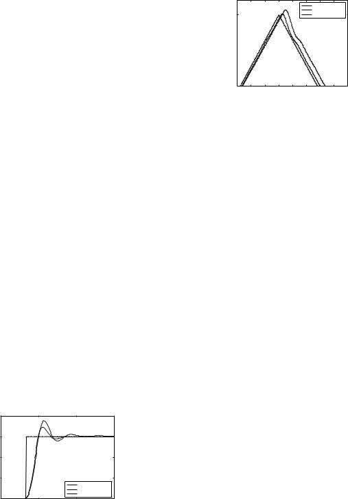
Out of 20 runs, 16 runs performed better than the handtuned solution. The BOR circuit has the following gains (realized on the FPAA): K: 0.001/us G: 9.45 G1: 0.333 G2: 6.67 G3: 0.333 G4: 81. This results in PID coefficients as KP = 17.9685, KI = 0.000333/us, KD = 0.6303 ms, and a DC offset of +1.0 V . The BOR fitness was −3.17e−3 as compared to −3.70e−3 that of the hand-tuned solution, a 14.3% error reduction. The time response of the handtuned and the BOR controller for a step input are shown in Figure 9. The hand-tuned and the BOR solution were also compared on a different reference signal which contained a triangular wave followed by a sine-wave. The time response of the two solutions for the tip of the triangular wave is shown in Figure 10. The squared error of BOR is 3.544e−5 is an order of magnitude better than that of handtuned solution (3.4746e−4). This shows that the solution of PSO is not specifically tuned to the reference signal used for fitness evaluation, but is a generic solution. The statistics imply that the probability that the PSO solution is worse than the hand-tuned solution is 0.2. If we do three runs and take the best solution, this probability goes down to 0.008, which is as low as 1 in 125 times.
|
1 |
|
|
|
|
0.75 |
|
|
|
(V) |
|
|
|
|
voltage |
0.5 |
|
|
|
|
|
|
|
|
|
0.25 |
|
|
|
|
|
|
|
input |
|
|
|
|
best solution |
|
|
|
|
handtuned solution |
|
0 |
8.5 |
9 |
9.5 |
|
8 |
|||
|
|
|
time (s) |
x 10−3 |
Figure 9. Time response of hand-tuned and evolved controllers, Experiment 1.
In Experiment 2, we did a preliminary study regarding adaptability of the PID controller. In this scenario, Plant 1 drifts (to Plant 2’s configuration). The controller must adapt
|
|
|
|
|
|
input |
|
|
|
|
|
|
|
|
best solution |
|
|
0.75 |
|
|
|
|
|
handtuned solution |
||
voltage (V) |
|
|
|
|
|
|
|
|
0.5 |
0.0115 |
0.012 |
0.0125 |
0.013 |
0.0135 |
0.014 |
0.0145 |
0.015 |
0.011 |
||||||||
time (s)
Figure 10. Time response of hand-tuned and evolved controllers on a new test signal, Experiment 1.
the PID coefficients for Plant 1 to suit Plant 2 via another self-tuning. Plant 2 has a gain of 6.912, natural frequency 1.0637 KHz and a damping ratio of 0.47. In open loop, Plant 2 shows oscillations and a steady state error of 5.712, settling time of 6.60 ms and a rise time of 1.942 ms for 5% accuracy. We assume that the original controller uses BOR solution for Plant 1. Upon switching to Plant 2, the error more than doubles, increasing from 3.165e−3 to 6.797e−3. We tested two strategies to tune the controller. The first strategy was to rerun PSO, while the second was to run PSO with the initial population seeded with the BOR solution for Plant 1 (similar to [8]). We believed that the second strategy would take less time to adapt.
We did 20 runs for each strategy with all parameters the same as earlier experiments. The fitness values of the BOR solutions for Strategy 1 and Strategy 2 were −5.727e−3 and −5.700e−3, respectively. This implied improvements of 15.7% and 16.1% over the solution of Plant 1. The average number of generations to converge for Strategies 1 and 2 were 17.6 and 5.65, respectively, meaning Strategy 2 was 67.9% faster. All solutions from Strategy 2 improved the BOR solution by more than 10%, while 60% of solutions from Strategy 1 did so. This shows that the plant can be re-adapted to a new plant more efficiently by running PSO with the BOR solution inserted in the initial population.
5 Summary and Future Work
We have presented a framework for a self-tuning analog PID controller. It overcomes traditional problems associated with FPAAs such as poor characterization and limited or coupled component parameter ranges. The framework overcomes these by using a model-free tuning method. It combines the advantages of low power, no quantization noise, high bandwidth and high speed in comparison to a self-tuning digital PID controller.
We implemented a prototype of this PID controller using a state-of-art commercially available FPAA, Anadigm’s AN221E04 and used Particle Swarm Optimization as the
tuning method. We developed a scheme to correct the variance in measurement and incorporated it into PSO. We showed that a self-tuned controller can outperform a handtuned solution. The optimization algorithm worked well despite the system offset and coupled ranges for different gain values.
Our future work will be directed toward both our prototype and framework. In terms of our prototype, we would like to incorporate search for the best ranges of gains (i.e. fc) into our software so the search can be informed by closed loop characteristics. This would improve upon our manual method of finding ZN coefficients which must be done in open loop and which does not support adaptation of a highly varying plant. We also plan to gauge the effect of using less precise ADCs with cost function evaluation in hardware. Finally, we are also investigating how topological search can facilitate better ranges for the PID coefficient values.
In terms of our framework, one issue we want to address is the limitations of our current prototype in which we employ a very versatile FPAA at the unfortunate cost of power consumption. We would like to design a custom made chip which is a re-tunable PID controller. This requires only variation in component values rather than both values and interconnections (which lead to high area, power and signal distortion). There are several continuous-time low power FPAA designs in the literature, and a PID chip design could be based on one of these architectures. For instance, a continuous-time OTA (operational transconductance amplifier) based PID controller could be designed, where varying the coefficients shall require only varying the bias currents. Such a chip together with a DSP processor running the tuning algorithm controlling a real plant would be the final test of our framework. Adaptive controllers would be very useful in a mobile robotic system with a small power budget. Figuring out when and how the robotic system can strobe the processor to go back into tuning mode is an open question. Perhaps some configuration of the internal sensors of the robot or polling of an error threshold will work. Finally, we would like to extend our framework to use other control strategies such as Smith controllers or fuzzy controllers and tuning methods such as those based on relays and phase locked loops.
References
[1]5th NASA / DoD Workshop on Evolvable Hardware (EH 2003), 9-11 July 2002, Chicago, IL, USA. IEEE Computer Society, 2003.
[2]7th NASA / DoD Workshop on Evolvable Hardware (EH 2005). IEEE Computer Society, 2005.
[3]K. J. Astrom and T. Hagglund. U.S. patent no. 4549123, method and an apparatus in tuning a pid regulator, 1985.
[4]D. Berenson, N. Estevez, and H. Lipson. Hardware evolution of analog circuits for in-situ robotic fault-recovery. In
Evolvable Hardware [2], pages 12–19.
[5]J. Crowe and M. Johnson. Frequency domain versus time domain methods in system identification. IEE Proc., Control Theory Appl., 147(2):196–204, 2000.
[6]J. L. M. do Amaral, J. F. M. do Amaral, C. C. Santini, R. Tanscheit, M. B. R. Vellasco, M. A. C. Pacheco, and A. Mesquita. Evolvable building blocks for analog fuzzy logic controllers. In Evolvable Hardware [1], pages 101– 110.
[7]G. Frantz. Digital signal processor trends. IEEE-MICRO, 20(6):52–59, Nov./Dec. 2000.
[8]G. W. Greenwood, E. Ramsden, and S. Ahmed. An empirical comparison of evolutionary algorithms for evolvable hardware. In Evolvable Hardware [1], pages 59–66.
[9]D. A. Gwaltney and M. I. Ferguson. Intrinsic hardware evolution for the design and reconfiguration of analog speed controllers for a dc motor. In Evolvable Hardware [1], pages 81–90.
[10]D. A. Gwaltney and M. I. Ferguson. Enabling the on-line intrinsic evolution of analog controllers. In Evolvable Hardware [2], pages 3–11.
[11]T. S. Hall, C. M. Twigg, P. Hasler, and D. V. Anderson. Developing large scale field programmable analog arrays for rapid prototyping. International Journal of Embedded Systems, 2004.
[12]H. Hjalmarsson and T. Birkeland. Iterative feedback tuning of linear time-invariant mimo systems. In 37th IEEE Conference on Decision and Control, pages 3893–3898, 1998.
[13]S. R. S. Inc. Sim 960 - 100 khz analog pid controller. http://www.thinksrs.com/downloads/PDFs/Catalog/SIM960c.pdf.
[14]M. A. Johnson and M. H. Moradi. PID Control. Springer Science+Business Media, 2005.
[15]J. Kennedy and R. Eberhart. Particle swarm optimization. In Proceedings of the Fourth IEEE International Conference on Neural Networks. IEEE Press, 1995.
[16]L. Ljung and K. Glover. A process identifier and its application to industrial control. Automatica, 17(1):71–86, 1981.
[17]D. Marsh. Programmable analogue ics challenge spiceandbreadboard designs. EDN Europe, pages 30–36, October 2001.
[18]Y. Shi and R. C. Eberhart. Empirical study of particle swarm optimization. In P. J. Angeline, Z. Michalewicz, M. Schoenauer, X. Yao, and A. Zalzala, editors, Proceedings of the Congress on Evolutionary Computation, volume 3, pages 1945–1950, Mayflower Hotel, Washington D.C., USA, 6-9 July 1999. IEEE Press.
[19]M. A. Terry, J. Marcus, M. Farrell, V. Aggarwal, and U. M. O’Reilly. Grace: Generative robust analog circuit exploration. Accepted in 9th European Conference on Genetic Programming, EVO-Workshops, EVOHOT track, 2006.
[20]J. G. Ziegler and N. B. Nichols. Optimum settings for automatic controllers. Trans. A.S.M.E., 64:759–765, 1942.