

Application of PICs and microcontrollers in the measurement and control of parameters in industry
.pdfApplication of PICs and microcontrollers in the measurement and control of parameters in industry
O. González, M. Rodríguez, A. Ayala, J. Hernández and S. Rodríguez
Department of Fundamental and Experimental Physics, Electronics and Systems, University of La Laguna, Tenerife, Canary Islands, Spain
E-mail: oghdez@ull.es
Abstract This paper describes the use of microcontrollers in low-cost control applications. The main feature of the system is the use of programmable integrated circuits (PICs) to perform direct control processes within a plant. In this work, a control model based on distributed functions in levels is proposed to increase control task efficiency. With reference to a previous model, an efficient and simple control system is suggested for industrial applications. The designed system distributes its supervisory and control tasks in different units using commercial microcontroller devices. The
results obtained with the previous system are described, which let us check the reliability and flexibility of the proposed model. Finally, several operational alternatives for the developed system are suggested.
Keywords actuators; measurement and control systems; microcontrollers; radiofrequency link; sensors
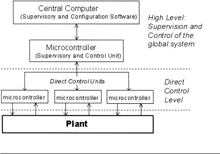
In order to reduce costs and optimise production, in many applications (e.g., industrial, agricultural) it is necessary to control several parameters, such as temperature, humidity or luminosity. Usually there are several sensors and actuators along the plant managed from some controller or computer system. Efficient systems share their functions at several levels, from a low, direct control level to higher levels (supervision and co-ordination control levels).1
The direct control level allows direct interaction with the plant. At this level, usually, there are microcontroller devices watching the measurements taken for its sensors and ordering actions by its actuators. These microcontrollers are located at several points along the plant. Each manages its own sensors and actuators, without considering more remote conditions of the plant or neighbouring points. This can be sufficient for many applications, but this control method presents some disadvantages such as: the control parameters are always fixed and they cannot be modified dynamically; moreover, if the microcontroller has no visualisation device, the user cannot know the conditions occurring in the zone; finally, every microcontroller works independently and this can be a problem in large plants.
The addition of superior control levels to the system can solve these problems. For example, a supervisory control level allows integration of all information about the plant in a single place. A simple supervisory system can be a device that manages and displays information from all the microcontrollers. Nevertheless, this system can be improved by including control tasks in the supervisory device. We are always looking to centralise control tasks in a single device (computer or other control
International Journal of Electrical Engineering Education 41/3
266 |
O. González et al. |
system). A more global vision of the whole plant should result in more accurate control actions.
As an example of an efficient control system, we may have a set of sensors and actuators managed by microcontrollers, and a high-performance central microcontroller monitoring all of them.2 This may be configured making use of a PC connected to it. In this sense, the purpose of this work is the design and implementation of a control system as previously mentioned. This control system is composed of the following parts:
•Direct control units of sensors and actuators
•Global control and supervisory unit of the system
•Supervisory and configuration software, for PC, of the system
Figure 1 depicts the block diagram of the proposed control system. The direct control unit for sensors and actuators is formed by one or more microcontroller supervising several zones in the plant. It obtains data from its sensors and regulates the conditions in the plant by means of its actuators. The supervisory and control unit (SCU) is composed of a high-performance microcontroller and it sets up a link with all the remote control units (RCU). It requests data from all the sensors and drives the actuation actions. The user, through a PC and the developed software, can display the conditions in the plant and configure or adjust the operation mode of the system.
Control units for the sensors and actuators
The control unit for the sensors and actuators is a device which is based on a PIC microcontroller (Programmable Integrated Circuit). Its main functions are measure-
Fig. 1 Hierarchical system levels.
International Journal of Electrical Engineering Education 41/3
PICs and microcontrollers in industry |
267 |
ment of environmental conditions and interaction with the plant by means of its actuators. All these tasks are managed through low-level software developed for the microcontroller. The features of PICs (capacity and operating speed) make them well suited for direct control tasks. In addition, they are small.3,4
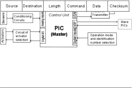
The block diagram of this control unit is shown in Fig. 2. The PICs have 5 analogue inputs connected to an internal 8-bit multichannel analogue-to-digital converter, an USART that allows synchronous and asynchronous communications, a synchronous serial port (SSP) for high-speed communications with other peripheral or microcontroller devices, and several digital I/O lines.5 Signal range from the sensors is adjusted through signal conditioning circuits which are connected to the analogue inputs. The actuator selection circuit is used to verify actuator states (ready/busy) and to send them suitable commands through digital port I/O lines.
A control unit of sensors and actuators can be composed of one or more of these PICs, where one of them is always the master controller and the others are their slaves. This possibility permits an increase in or extension of the number of acquisition channels and digital control ports. The master PIC sets up communications with the other remote control units (RCU) or with the supervisory and control unit (SCU) through a RF transmission circuit. During communications between units, they interchange messages. These messages are aimed at sharing information about its channel data and actuation data. Therefore, we can talk about four types of messages: data messages, link messages, actuation messages and status messages. The message format is shown in Fig. 3. This one is based on UDP protocol for computer network communications.6 Each message field, with the exception of the data field, is a byte (8 bits). The size of the data is related to the message type. The source and destination fields determine the transmitter and the desired receiver of the message.
Fig. 2 Control unit.
Fig. 3 Message format.
International Journal of Electrical Engineering Education 41/3

268 |
O. González et al. |
Every control unit has an 8-bit identification number (0–255). This number is used to check when a message is aimed at the unit. The SCU is identified by the number zero. Thus, a unit only processes messages whose destination field agrees with its identification number. The length field indicates the number of bytes in the message, excluding the checksum byte. This last is the sum of the remaining bytes of the message and, therefore, it allows detection of possible communication errors. Finally, the command field has four possible values to identify the message type. The SCU uses data messages to request channel data from the control units. These last will use data messages to send information to the SCU, adding this in the data field. The SCU indicates actuation actions to RCUs using actuation messages. These actuation data are added in the data field of the messages. The status messages are used in a similar way to data messages. In this case, the RCUs only respond to the messages sent by the SCU, without including any information in the data field. This message type allows the SCU to verify whether a certain control unit is active. Finally, the link messages allow the sending of messages from a unit towards another remote one, using a third unit which is closer to the first.
A single PIC (the master) can control up to five analogue channels. However, there are situations where more channels are needed to supervise the zone. Adding more PICs (slaves), we can increase this number. In these cases, the new PICs will use the SSP for communicating with the master PIC. In these communications, they will interchange actuation data and channel data. Moreover, these communications are always driven by the master. Therefore, the source and destination fields are not necessary and they disappear in these messages. On the other hand, the link and status messages are not necessary either. The slave PICs in a RCU do not utilise the USART, because only the master needs to communicate with other control units.
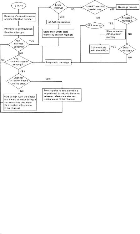
The maximum number of actuators that can be controlled by a PIC is equal to its number of acquisition channels or sensors. The environmental conditions measured by the sensor are used to determine the commands to send towards its actuator. However, the SCU can occasionally control the actuators of RCUs independently from the measurements of the sensors. The PICs manage their actuators using a digital control line. They send pulses as large as the intensity of the actuation that must be done. Thus, short pulses indicate weak actuations and large pulses indicate strong actuations. The PIC only sends these pulses when the actuator is ready. The actuator uses a status line to indicate whether it is busy. A PIC can distinguish between two actuation types: actuations with an external limit switch and actuations based on error. In the first case, it sends pulses with a defined duration. This actuation type is called global actuation, because the actuations are remotely managed by the SCU considering the conditions in the whole plant. In the other case, the PIC uses its sensors to control the conditions and sends pulses with a duration proportional to the error between the measured value and the desired reference value. This type of actuation is named local actuation, because the RCU manages its actuators by itself. The SCU indicates, using actuation messages, the actuation mode (global or local) of every RCU channel.
Internally, each PIC is programmed to respond to three interrupt types: interrupts of the communication ports, timer interrupts and interrupts of the analogue-to-digital
International Journal of Electrical Engineering Education 41/3

PICs and microcontrollers in industry |
269 |
converter. At any moment, the PIC is occupied in control tasks, but it can be interrupted by previous internal modules.
Supervisory and control unit
The supervisory and control unit (Fig. 4) is composed of a high-performance microcontroller.7 This must remotely manage the correct operation of every RCU. The microcontroller system used has two independent serial ports (one UART by port). One of them is used for communicating with other control units, and the other port is used for communicating with the PC.
For the connection with the PC, wires can be used locating the SCU close to it. In the communications with RCUs, wireless links are the most suitable in most situations, because they allow us to work over wide areas. In our design, we have used a radiofrequency link, but another transmission system can be used adapting its signals to the communications ports of microcontrollers.
The main function of a microcontroller is to control, from its remote position, the conditions registered at the measurement points. A measurement point is a RCU with or without actuators. If the main function of the RCU is to link communications between two other units, we have a link point. Therefore, these can be used to solve problematic communications with remote units. Such a situation is shown in Fig. 5. The RCU number 3 is unreachable from the SCU in a direct way. Other PICs, like RCUs 1 and 2, are used to set up this link. This is possible because every measurement point has a different identification number.
The SCU communicates with RCUs to request its channel data and to order actuation actions. The number of PICs in the RCU is ignored by the SCU. It considers the RCU as a set of sensors and actuators managed by a microcontroller device. Therefore, only for the SCU are the channels and their characteristics important. The
Fig. 4 Supervisory unit connected to PC.
Fig. 5 Communication between microcontroller and a remote measurement point.
International Journal of Electrical Engineering Education 41/3

270 |
O. González et al. |
SCU uses an internal table where it stores the characteristics of each channel: reference values, actuation mode, time for the next communication with a RCU, etc. All this information allows there to be actuation points – where all the actuators are located – which are different from the measurement points.
The channel data about measurement points are 8-bit numbers (0–255). For the SCU the nature of the measurement obtained by a sensor is not important. Thus, SCU and RCUs work with numbers and not with physical magnitudes. The SCU stores all the information that it needs in its internal memory (in the internal tables). Therefore, it does not need to communicate with a PC during its normal operation. In fact, the user inits communication between PC and SCU exclusively to modify these internal tables or to read channel data. Also, the user can only participate in control tasks using the previous method.
Supervisory and configuration software
The supervisory and configuration software is a tool that allow us to configure the actuation data of the SCU. This program uses the serial port of the PC for communicating with the SCU.8 The software allows the supervision and configuration of the SCU. In fact, the software has an automatic supervisory mode. In this mode, the software periodically requests the channel data to the SCU and displays this information in the screen.
For communicating with the SCU, the software uses several types of messages: data retrieval messages, configuration messages and connection messages. The first byte of these messages identifies the message type. Additional data complete the messages. These finish with a last checksum byte. The data retrieval messages are used to request channel data about the measurement points to the SCU. The configuration messages allow the user to modify the internal tables of the SCU and, therefore, to modify the actuation modes of RCUs. These types of messages also allow addition or removal of measurement points, to modify baud rate of transmissions, etc. Finally, the connection messages check the state of the links with RCUs. Initially, the SCU uses these messages to check the reliability of the communication with every RCU.
Results
A system with a measurement point has been developed to check the previous control model. The measurement point is composed of a master PIC with several sensors (temperature and humidity sensors). A signal conditioning circuit has also been designed to adapt the sensor output to the input of the PIC A/D converter (Fig. 6). In this circuit, two input buffers isolate sensor signals of the operational-amplifier in adder-inverter configuration.9 The last inverter removes the previous inversion of voltage.
The programs loaded in PIC microcontrollers (Fig. 7) and the central microcontroller (Fig. 8), as well as the configuration software, has also been implemented. There are many situations which the developed system has not allowed us to check
International Journal of Electrical Engineering Education 41/3
PICs and microcontrollers in industry |
|
|
|
|
|
271 |
|||
V+ |
Offset |
|
|
|
|
|
|
|
|
|
selector |
|
|
|
|
|
|
|
|
R |
+ |
|
R |
|
|
|
|
INVERTER |
|
|
V+ |
|
|
|
|
R |
|
||
|
V– |
|
|
|
ADDER |
|
+ |
|
|
|
|
R |
|
|
|
|
|||
V– |
– |
|
+ |
|
|
V+ |
|
||
|
|
|
|
|
|
||||
|
|
|
V+ |
R |
|
V– |
conditioned |
||
|
|
|
|
|
|
||||
|
|
|
|
|
|
|
– |
||
|
|
Input |
|
|
V– |
|
|
output |
|
|
+ |
|
– |
|
|
|
|||
From |
buffer |
Rvar |
|
|
|
|
|
||
|
|
|
|
|
|
||||
sensor |
V+ |
|
|
|
R |
|
|
R |
|
|
– V– |
|
|
|
|
|
|
|
|
|
|
Gain |
|
|
|
|
|
|
|
|
|
|
selector |
|
|
Vout = (R/Rvar)Vin + Voffset |
|||
Fig. 6 Signal conditioning.
Fig. 7 Flowchart of the program loaded in the PIC microcontrollers memory.
(actuations, communications between slaves and the master of a RCU, communications with far RCUs using links points, etc.). However, these were simulated using development software contributed by manufacturers of microcontrollers.
In the developed system, a radiofrequency link has been used.10 As previously mentioned, this communication system is well suited to these situations. Also, the
International Journal of Electrical Engineering Education 41/3

272 |
O. González et al. |
Fig. 8 Flowchart of the program loaded in the microcontroller memory.
Fig. 9 Radiofrequency system.
microcontrollers do not allow the simultaneous transmission and reception of messages. On the other hand, only one unit can be transmitting a message at any moment (the destination unit of a previous message). In Fig. 9 is shown the block diagram of this radiofrequency system. We can see how the device that uses the antenna (receiver/transmitter) is controlled by a switch. The control signal for switches is managed by the microcontrollers.
The developed system was tested during long periods of time and we obtained satisfactory results. In Fig. 10 are shown the temperature measurements taken on one of these test days. Each measurement was taken at one minute interval using an integrated temperature sensor with an accuracy of 0.5°C. The graphical representation was obtained by making use of the developed software.
International Journal of Electrical Engineering Education 41/3

PICs and microcontrollers in industry |
273 |
Fig. 10 Temperature measurement on one day.
Discussion
The system described above offers many practical possibilities. We have a set of measurement points directly controlled by microcontroller PICs. A highperformance microcontroller supervises remotely the correct operation of the whole system. This microcontroller can be connected to a PC for configuring. The control system can work in many modes.
The simplest operational mode is the supervisory mode. In this, the central microcontroller requests channel data from the measurement points and displays them on the PC screen. It can also store these data in its internal memory for several days before sending them to the PC. When we want to interact with the environment, actuators must be used. The system allows global and local actuations. Thus, the actuations can be oriented to regulate local conditions or they can take into account the conditions in the whole plant. Also, these actuations can be error-based or onoff actuations.
Therefore, we can affirm that the proposed control system can be adapted to many situations, giving suitable values to the control parameters.
References
1Curtis D. Johnson, Process Control Instrumentation Technology (Prentice Hall, Englewood Cliffs, NJ, 1997).
International Journal of Electrical Engineering Education 41/3

274 |
O. González et al. |
2M. Rodríguez, A. Ayala, F. Herrera and F. Priano, ‘Greenhouse automation through computer and Hertzian link’, Intl. J. Elec. Enging Educ., 33 (1996), 66–88.
3J. M. Angulo, E. Martín and I. Angulo, Microcontroladores PIC, (Paraninfo, 1997).
4J. M. Angulo and I. Angulo, Microcontroladores PIC. Diseño práctico de aplicaciones (McGrawHill, NewYork, 1997).
5Microchip, www.microchip.com
6W. Stallings, Data and Computer Communications (Prentice-Hall, Englewood Cliffs, 2000).
7Tern Inc.: www.tern.com
8Craig Peacock, Interfacing the Serial / RS232 Port (2000), http://www.beyondlogic.org/serial/serial.htm
9D. Schilling and C. Belove, Circuitos Electrónicos Discretos e Integrados (Marcombo, 1985).
10Aurel wireless: www.aurel.it
International Journal of Electrical Engineering Education 41/3