

CIR errata Oct98
.pdfIrDA Control Errata, 1998
Table 4.2 (4.1)
|
|
Peripherals |
Peripherals at the NCL |
|
|
||
|
IrDA 1.1 |
at the CL |
Entire Polling |
||||
Host mode |
polling rate |
||||||
device |
polling rate |
Cycle Time |
|||||
|
|
|
|||||
|
|
Short |
Long |
Short |
|
|
|
|
|
|
0 |
8 |
|
8 TSS |
|
|
|
|
|
||||
|
|
|
1 |
7 |
1TSL + 7 TSS |
||
|
|
|
|
|
|
|
|
|
|
0 |
2 |
6 |
2TSL |
+ 6 TSS |
|
|
|
3 |
5 |
3TSL |
+ 5 TSS |
||
|
|
|
|||||
Mode-1 |
0 |
|
4 |
4 |
4TSL |
+ 4 TSS |
|
|
5 |
1 |
5TSL |
+ 1 TSS |
|||
|
|
|
|||||
|
|
1 |
|
7 |
|
10 TSS |
|
|
|
|
|
||||
|
|
2 |
0 |
6 |
|
12 TSS |
|
|
|
3 |
5 |
|
20 TSS |
||
|
|
|
|
||||
|
|
4 |
|
1 |
|
17 TSS |
|
Mode-2 |
1 |
0 |
0 |
2 |
TIrDA |
+ 2 TSS |
|
The table of Specification 1.0 has unnecessary ruled-lines. It should be corrected as shown below.
Table 4.2 Maximum number of peripherals that can be accommodated in a Host mode
Table4.4 (4.2.3)
The table of Specification 1.0 has unnecessary ruled-lines. It should be corrected as shown below.
|
|
Frame from Host device |
|
||
|
|
Meaning |
|
1 |
0 |
MAC |
D7 |
Packet direction |
|
1 ( Host is sending ) |
|
Control |
D6 |
Bind timer restarted |
|
Restarted |
Not Restarted |
field |
D5 |
Long frame enable |
|
Enable |
Disable |
|
D4 |
Device hailing |
Hailing |
Not hailing |
Peripheral |
D3 |
( Peripheral Address ) |
- |
- |
Address |
D2 |
- |
- |
|
field |
D1 |
|
- |
- |
|
D0 |
|
- |
- |
|
|
Frame from Peripheral device |
|||
|
|
Meaning |
1 |
|
0 |
MAC |
D7 |
Packet direction |
0 ( Peripheral is sending ) |
||
Control |
D6 |
Polling Request |
Request |
|
No Request |
field |
D5 |
( Reserved ) |
|
( Reserved ) |
|
|
D4 |
( Reserved ) |
|
( Reserved ) |
|
Peripheral |
D3 |
( Peripheral Address ) |
- |
|
- |
Address |
D2 |
- |
|
- |
|
field |
D1 |
|
- |
|
- |
|
D0 |
|
- |
|
- |
Table 4.4 MAC Control field
11

IrDA Control Errata, 1998
Table 4.6(4.5.1)
The table of Specification 1.0 has unnecessary ruled-lines. It should be corrected as shown below.
Bits |
Denotes |
Meaning |
|
D0 |
Upper Layer Protocol |
0 |
– Host does not support HID-IrDA Control Bridge |
|
|
1 |
– Host supports HID-IrDA Control Bridge |
D1 |
|
0 |
– Host does not support HA-LLC |
|
|
1 |
– Host supports HA-LLC |
D2 |
|
Reserved ( for the 3rd protocol ) |
|
D3 |
|
Reserved ( for the 4th protocol ) |
|
D4-D15 |
Pre-assigned number or |
|
|
|
a pseudo random number |
|
|
Table 4.6 HostID field Definitions
Table 4.7(4.5.1)
The table of Specification 1.0 has unnecessary ruled-lines. It should be corrected as shown below.
Bits |
Denotes |
Meaning |
|
D0 |
Upper Layer Protocol |
0 – Host does not support HID-IrDA Control Bridge |
|
|
|
1 |
– Host supports HID-IrDA Control Bridge |
D1 |
|
0 |
– Host does not support HA-LLC |
|
|
1 |
– Host supports HA-LLC |
D2 |
|
Reserved ( for the 3rd protocol ) |
|
D3 |
|
Reserved ( for the 4th protocol ) |
|
D4 |
Support for Long frames from host |
0 – Host does not support long frames from host |
|
|
|
1 |
– Host supports long frames from host |
D5 |
Support for Long frames to host |
0 – Host does not support long frames to host |
|
|
|
1 |
– Host supports long frames to host |
D6-D15 |
Reserved |
|
|
|
|
|
|
Table 4.7 HostInfo field Definitions
Table 4.9(4.5.2)
The table of Specification 1.0 has unnecessary ruled-lines. It should be corrected as shown below.
Bits |
Denotes |
Meaning |
|
D0 |
Upper Layer Protocol |
0 – Peripheral does not support HID-IrDA Control Bridge |
|
|
|
1 |
– Peripheral supports HID-IrDA Control Bridge |
D1 |
|
0 |
– Peripheral does not support HA-LLC |
|
|
1 |
– Peripheral supports HA-LLC |
D2 |
|
Reserved ( for the 3rd protocol ) |
|
D3 |
|
Reserved ( for the 4th protocol ) |
|
D4 |
Support for Long frames from host |
0 – Peripheral does not support long frames from host |
|
|
|
1 |
– Peripheral supports long frames from host |
D5 |
Support for Long frames to host |
0 – Peripheral does not support long frames to host |
|
|
|
1 |
– Peripheral supports long frames to host |
D6 |
Max. Polling Rate |
0 – NCL Polling Rate |
|
|
|
1 |
– CL Polling Rate |
D7-D15 |
Reserved |
|
|
|
|
|
|
Table 4.9 PeripheralInfo field Definitions
12
IrDA Control Errata, 1998
2.2 DC-Biased Scheme
ADDITION
Following descriptions are about the method of reducing the interference on legacy remote control systems (the DCBiased scheme).
The 16-Pulse Sequence Modulation (16PSM) scheme of IrDA Control is designed to decrease IR energy on the frequency band 33kHz - 40kHz, however, it still has influence on receivers of legacy remote control systems.
As shown in Appendix H, the DC-Biased scheme can obtain a great improvement for the reduction of the interference, moreover it has the interoperability with the original 16PSM scheme. Therefore, the DC-Biased scheme is one of the solutions for the coexistence with legacy remote control systems and it should be appended to the Final Specification 1.0. The descriptions are as follows.
The following paragraph needs to be appended next to the second paragraph in section 3.1(Overview), in order to give an introduction to Appendix described below.
“However, receivers of many legacy remote control systems also detect other frequencies from 33kHz - 40kHz band and therefore the 16PSM scheme still has influence on such remote control systems. So, for those systems, which operate under the existence of legacy remote control systems, it is highly recommended to implement the DC-Biased scheme described in Appendix H.”
In addition, the following appendix needs to be added, since the IrDA-Control can be greatly improved in the interference on legacy remote control system with this scheme.
Appendix H. Reduction of interference on legacy remote control systems
H.1 Introduction
As shown in Figure A.1, the spectrum of the 16PSM signal defined in chapter 3 can be divided into two components. One is a pass band component around 1.5MHz, and another is a base band component around 0Hz.
The pass band component is essential, while the base band component is not necessary for communication.
The 16-Pulse Sequence Modulation (16PSM) scheme of IrDA-Control is designed so that its base band component minimizes the interference on the frequency band used by legacy remote control systems. However, it still has influence on receivers of those legacy remote control systems, which also detect other frequencies from 33kHz - 40kHz band.
The DC-Biased scheme eliminates the unnecessary base band component of 16PSM signal and widely decreases the interference on legacy remote control systems at the cost of 2.66 times of IR power.
For those IrDA-Control systems, which operate under the existence of legacy remote control systems, it is highly
13

IrDA Control Errata, 1998
recommended to implement the DC-Biased scheme described in this section.
H.2 DC-Biased Scheme
The energy of base band component caused by the alternation of the existence of the SEPC
Figure H.1 shows the original IrDA-Control signal defined in chapter 3 and Figure H.2 shows the DC-Biased IrDAControl signal. In the DC-Biased scheme, IR is continuously emitted at half intensity of the peak of 1.5MHz sub-carrier pulse, among every SEPC. This scheme keeps the DC level in the packet constant and eliminates the base band component.
SEPC
One Packet
Figure H.1 Original IrDA-Control Signal
Continuous IR
One Packet
Figure H.2 DC-Biased IrDA-Control Signal
The performance of this scheme highly depends on the intensity of the continuous IR emission part. Therefore, it is preferable that the IR intensity of the continuous emission part is precisely same as the average IR intensity of SEPC.
14

IrDA Control Errata, 1998
H.3 Effectiveness of DC-Biased Scheme
Figure H.3 and Figure H.4 show the spectrums of the original IrDA-Control signal and the DC-Biased IrDA-Control signal respectively. As shown in those figures, the energy besides the range of 33kHz to 40KHz observed in Figure H.3 almost disappears in Figure H.4, because this scheme eliminates the base band component.
Figure H.5 shows the experimental environment of measurement of the effectiveness of the DC-Biased scheme. As shown in the figure, an IrDA-Control signal transmitter is placed in front of the IR receiver of a TV (SHARP Network Vision 32C-PC11) at a distance of 1m. And the probabilities of the TV controlled successfully in 20 times trials are measured at each distance (a) between the TV and the remote-controller while the following 3 signal patterns are transmitted at 160mW/sr from the IrDA-Control signal transmitter.
1.Original IrDA-Control Signal
2.DC-Biased IrDA-Control Signal
3.No Signal
One short packet2 signal is transmitted in every 27.6ms in condition 1 and 2. This simulates the situation where an active peripheral is existing in front of the TV.
Table H.1 shows the results of this experimental test on the TV and its remote controller.
As shown in Table H.1, a large improvement can be observed by applying the DC-Biased scheme. While there is no distance where the probability become more than 60% when the original IrDA-Control signal is being transmitted, the performance is almost the same as no ambient noise when the DC-Biased IrDA-Control signal is being transmitted.
1TSOP 5000 series (TEMIC) is used for remote controller receiver in this TV.
2The packet length is 11 byte from Host Address to CRC flag.
15

IrDA Control Errata, 1998
Spectrum of
IrDA-Control
signal
Spectrum of ambient
noise
Figure H.3 Spectrum of original IrDA-Control Signal
Spectrum of
DC-Biased 
signal
Spectrum of ambient
noise
Figure H.4 Spectrum of DC-Biased IrDA-Control Signal
16

IrDA Control Errata, 1998
TV
Front
Remote Controller
a
(200mW/sr)
 IrDA-Control signal 1m transmitter
(160mW/sr)
Figure H.5 Environment of the Experiment
Probability of TV controlled successfully
|
1 |
2 |
3 |
|
|
DC-Biased |
No am bient |
Distance(m ) |
IrDA Control |
Schem e |
noise |
|
|
|
|
1 |
35% |
100% |
100% |
2 |
45% |
100% |
100% |
3 |
45% |
100% |
100% |
4 |
60% |
100% |
100% |
5 |
35% |
100% |
100% |
6 |
35% |
100% |
100% |
7 |
35% |
100% |
100% |
8 |
30% |
100% |
100% |
9 |
45% |
100% |
100% |
10 |
40% |
100% |
100% |
11 |
40% |
100% |
100% |
12 |
5% |
100% |
100% |
13 |
0% |
90% |
100% |
14 |
0% |
90% |
100% |
15 |
0% |
80% |
95% |
Table H.1
17

IrDA Control Errata, 1998
3. Open Errata
3.1 Appendix D
MODIFICATION
The errors to be modified in this section are all in relation to Appendix D, in which some examples of packet traffic profiles based on MAC rules are illustrated. However these examples in Final Specification 1.0 contain some errors in both sentences and figures because the descriptions in Appendix D have not completely been updated since the Specification draft version 0.8. These are to be amended here.
Additionally, the Final Specification 1.0 includes some errors, which are caused by operation for editing, such as caption lacking. These are also to be amended.
Figure D.9 (D.2)
According to the description of Table 4.2 (in section 4.2), the maximum number of peripherals at the NCL polling rate is seven under existing only one CL polling rate peripheral.
Therefore, change the first sentence of the paragraph from – When the number of CL peripherals at the CL polling rate is one, the maximum number of peripherals at the NCL polling rate, which can be bound, is twelve – to “When the number of CL peripherals at the CL polling rate is one, the maximum number of peripherals at the NCL polling rate, which can be bound, is seven”.
For conformance with above modification, replace with the following figure.
Basic polling cycle time
Entire polling cycle time
time |
|
|
(Polling 1 CR and 3 NR’s) |
CL1? CL1 |
N1? |
N2? |
N3? N3 |
|
|
|
(Polling 1 CR and the next 3 NR’s) |
CL1? |
N4? |
N5? |
N6? |
|
|
|
(Polling 1 CR and the last 1 NR) |
CL1? CL1 |
N7? N7 |
(repeat these cycles.)
Polling CR’s |
Polling NR’s |
|
Packet to/from CR |
|
|
|
Host |
|
|
|
|
|
|
|
Peripheral |
|
|
|
|
|
|
? Host polls peripheral if it has data |
|
|
|
|
Peripherals have no data to respond |
|
|
CR:peripheral at the CL polling rate |
|
|
|
NR:peripheral at the NCL polling rate |
|
Figure D.9 Example of packet traffic in Mode-1 (1 CL and maximum NCL)
Figure D.10 (D.2)
18

IrDA Control Errata, 1998
According to the description of Table 4.2 (in section 4.2), the maximum number of peripherals at the NCL polling rate is six under existing two CL polling rate peripherals.
Therefore, change the first sentence of the paragraph from – When the number of CL peripherals at the CL polling rate is two, the maximum number of peripherals at the NCL polling rate, which can be bound, is eight – to “When the number of CL peripherals at the CL polling rate is two, the maximum number of peripherals at the NCL polling rate, which can be bound, is six”.
For conformance with above modification, replace with the following figure.
Entire polling cycle time
|
|
Basic polling cycle time |
|
|||
time |
CL1 |
CL2? |
CL2 |
N1? |
N1 |
(Polling 2 CR’s and 2 NR’s) |
CL1? |
N2? |
|||||
(Polling 2 CR’s and the next 2 NR’s)
CL1? |
CL2? CL2 |
N3? |
N4? |
|
|
|
|
|
(Polling 2 CR’s and the last 2 NR’s) |
CL1? |
CL1 |
CL2? |
N5? |
N6? |
N6 |
|
|
|
|
|
(Repeat these cycles.) |
Polling CR’s |
Polling NR’s |
|
Packet to/from CR |
|
Host |
||
|
Peripheral
? Host polls peripheral if it has data  Peripherals have no data to respond CR:peripheral at the CL polling rate NR:peripheral at the NCL polling rate
Figure D.10 Example of packet traffic in Mode-1 (2CL and maximum NCL)
Figure D.11 (D.2)
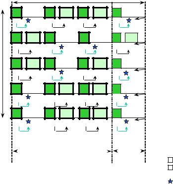
According to the description of Table 4.2 (in section 4.2), the maximum number of peripherals at the NCL polling rate is five under existing three CL polling rate peripherals.
Therefore, change the first sentence of the paragraph from – When the number of CL peripherals at the CL polling rate is three, the maximum number of peripherals at the NCL polling rate, which can be bound, is four – to “When the number of CL peripherals at the CL polling rate is three, the maximum number of peripherals at the NCL polling rate, which can be bound, is five”.
For conformance with above modification, replace with the following figure.
19
IrDA Control Errata, 1998
Entire polling cycle time
|
|
Basic polling cycle time |
|
|
|||
time |
|
|
|
|
|
|
|
CL1? |
|
CL2? |
CL2 |
CL3? |
CL3 |
N1? |
|
CL1? |
CL1 |
CL2? |
|
CL3? |
|
N2? |
N2 |
CL1? |
CL1 |
CL2? |
|
CL3? |
CL3 |
N3? |
|
CL1? |
|
CL2? |
CL2 |
CL3? |
CL3 |
N4? |
|
CL1? |
CL2? |
CL2 |
CL3? |
CL3 |
N5? |
(Polling 3 CR’s and 1 NR)
(Polling 3 CR’s and next 1 NR)
(Polling 3 CR’s and next 1 NR)
(Polling 3 CR’s and next 1 NR)
(Polling 3 CR’s and last 1 NR)
(Repeat these cycles.)
|
|
|
|
|
|
Packet to/from CR |
Polling CR’s |
Polling NR’s |
|
|
|||
|
|
Host |
||||
|
||||||
|
|
|
|
|
|
|
|
|
|
|
|
|
Peripheral |
|
|
|
|
|
|
|
|
|
|
|
|
? Host polls peripheral if it has data |
|
|
|
|
|
|
|
Peripherals have no data to respond |
|
|
|
|
|
CR:peripheral at the CL polling rate |
|
|
|
|
|
|
NR:peripheral at the NCL polling rate |
|
Figure D.11 Example of packet traffic in Mode-1 (3CL and maximum NCL)
Figure D.12 (D.2)
Replace Figure D.12, which lacks caption and some words in the Final Specification 1.0, with the following figure.
20