

Dongle interface V1
.2.pdfInfrared Data Association
Infrared Dongle Interface
Version 1.2
Date: 4 - 26 - 1999
Authors:
Franco Iacobelli (National Semiconductor Corp.)
Bill Weiser (Extended Systems Company)
Contributors:
Ray Chock (Calibre Inc.)
Chee-Zen Chin, Raymond Quek (Hewlett-Packard Company)
Lichen Wang, Keming Yeh (Actisys Corp.)
Document Status
Version 1.0 was approved at the IrDA meeting on July 22, 1998 Version 1.1 was presented at the IrDA meeting on October 12, 1998
Version 1.2 was presented at the IrDA meeting on April 12, 1999. This version contains only a small change in table 5-1. The ID code for the Vishay-Telefunken TFDS6500 transceiver has been changed from 1001b to 1011b.
2
INFRARED DATA ASSOCIATION (IrDA) - NOTICE TO THE TRADE -
SUMMARY:
Following is the notice of conditions and understandings upon which this document is made available to members and nonmembers of the Infrared Data Association.
∙Availability of Publications, Updates and Notices
∙Full Copyright Claims Must be Honored
∙Controlled Distribution Privileges for IrDA Members Only
∙Trademarks of IrDA - Prohibitions and Authorized Use
∙No Representation of Third Party Rights
∙Limitation of Liability
∙Disclaimer of Warranty
∙Product Testing for IrDA Specification Conformance
IrDA PUBLICATIONS and UPDATES:
IrDA publications, including notifications, updates, and revisions, are accessed electronically by IrDA members in good standing during the course of each year as a benefit of annual IrDA membership. Electronic copies are available to the public on the IrDA web site located at irda.org. Requests for publications, membership applications or more information should be addressed to:
Infrared Data Association, P.O. Box 3883, Walnut Creek, California, U.S.A. 94598; or e-mail address: info@irda.org; or by calling (925) 943-6546 or faxing requests to (925) 943-5600.
COPYRIGHT:
1.Prohibitions: IrDA claims copyright in all IrDA publications. Any unauthorized reproduction, distribution, display or modification, in whole or in part, is strictly prohibited.
2.Authorized Use: Any authorized use of IrDA publications (in whole or in part) is under NONEXCLUSIVE USE LICENSE ONLY. No rights to sublicense, assign or transfer the license are granted and any attempt to do so is void.
TRADEMARKS:
1.Prohibitions: IrDA claims exclusive rights in its trade names, trademarks, service marks, collective membership marks and feature trademark marks (hereinafter collectively "trademarks"), including but not limited to the following trademarks: INFRARED DATA ASSOCIATION (wordmark alone and with IR logo), IrDA (acronym mark alone and with IR logo), IR logo and MEMBER IrDA (wordmark alone and with IR logo). Any unauthorized use of IrDA trademarks is strictly prohibited.
2.Authorized Use: Any authorized use of an IrDA collective membership mark or feature trademark is by NONEXCLUSIVE USE LICENSE ONLY. No rights to sublicense, assign or transfer the license are granted and any attempt to do so is void.
NO REPRESENTATION of THIRD PARTY RIGHTS:
IrDA makes no representation or warranty whatsoever with regard to IrDA member or third party ownership, licensing or infringement/non-infringement of intellectual property rights. Each recipient of IrDA publications, whether or not an IrDA member, should seek the independent advice of legal counsel with regard to any possible violation of third party rights arising out of the use, attempted use, reproduction, distribution or public display of IrDA publications.
3
IrDA assumes no obligation or responsibility whatsoever to advise its members or non-members who receive or are about to receive IrDA publications of the chance of infringement or violation of any right of an IrDA member or third party arising out of the use, attempted use, reproduction, distribution or display of IrDA publications.
LIMITATION of LIABILITY:
BY ANY ACTUAL OR ATTEMPTED USE, REPRODUCTION, DISTRIBUTION OR PUBLIC DISPLAY OF ANY IrDA PUBLICATION, ANY PARTICIPANT IN SUCH REAL OR ATTEMPTED ACTS, WHETHER OR NOT A MEMBER OF IrDA, AGREES TO ASSUME ANY AND ALL RISK ASSOCIATED WITH SUCH ACTS, INCLUDING BUT NOT LIMITED TO LOST PROFITS, LOST SAVINGS, OR OTHER CONSEQUENTIAL, SPECIAL, INCIDENTAL OR PUNITIVE DAMAGES. IrDA SHALL HAVE NO LIABILITY WHATSOEVER FOR SUCH ACTS NOR FOR THE CONTENT, ACCURACY OR LEVEL OF ISSUE OF AN IrDA PUBLICATION.
DISCLAIMER of WARRANTY:
All IrDA publications are provided "AS IS" and without warranty of any kind. IrDA (and each of its members, wholly and collectively, hereinafter "IrDA") EXPRESSLY DISCLAIM ALL WARRANTIES, EXPRESS OR IMPLIED, INCLUDING BUT NOT LIMITED TO, THE IMPLIED WARRANTIES OF MERCHANTABILITY AND FITNESS FOR A PARTICULAR PURPOSE AND WARRANTY OF NONINFRINGEMENT OF INTELLECTUAL PROPERTY RIGHTS.
IrDA DOES NOT WARRANT THAT ITS PUBLICATIONS WILL MEET YOUR REQUIREMENTS OR THAT ANY USE OF A PUBLICATION WILL BE UN-INTERRUPTED OR ERROR FREE, OR THAT DEFECTS WILL BE CORRECTED. FURTHERMORE, IrDA DOES NOT WARRANT OR MAKE ANY REPRESENTATIONS REGARDING USE OR THE RESULTS OR THE USE OF IrDA PUBLICATIONS IN TERMS OF THEIR CORRECTNESS, ACCURACY, RELIABILITY, OR OTHERWISE. NO ORAL OR WRITTEN PUBLICATION OR ADVICE OF A REPRESENTATIVE (OR MEMBER) OF IrDA SHALL CREATE A WARRANTY OR IN ANY WAY INCREASE THE SCOPE OF THIS WARRANTY.
LIMITED MEDIA WARRANTY:
IrDA warrants ONLY the media upon which any publication is recorded to be free from defects in materials and workmanship under normal use for a period of ninety (90) days from the date of distribution as evidenced by the distribution records of IrDA. IrDA's entire liability and recipient's exclusive remedy will be replacement of the media not meeting this limited warranty and which is returned to IrDA. IrDA shall have no responsibility to replace media damaged by accident, abuse or misapplication. ANY IMPLIED WARRANTIES ON THE MEDIA, INCLUDING THE IMPLIED WARRANTIES OF MERCHANTABILITY AND FITNESS FOR A PARTICULAR PURPOSE, ARE LIMITED IN DURATION TO NINETY (90) DAYS FROM THE DATE OF DELIVERY. THIS WARRANTY GIVES YOU SPECIFIC LEGAL RIGHTS, AND YOU MAY ALSO HAVE OTHER RIGHTS WHICH VARY FROM PLACE TO PLACE.
COMPLIANCE and GENERAL :
Membership in IrDA or use of IrDA publications does NOT constitute IrDA compliance. It is the sole responsibility of each manufacturer, whether or not an IrDA member, to obtain product compliance in accordance with IrDA Specifications.
All rights, prohibitions of right, agreements and terms and conditions regarding use of IrDA publications and IrDA rules for compliance of products are governed by the laws and regulations of the United States. However, each manufacturer is solely responsible for compliance with the import/export laws of the countries in which they conduct business. The information contained in this document is provided as is and is subject to change without notice.
4
1.0 SCOPE
The intent of this proposal is to define an interface that allows interoperation between IR dongles and desktop systems from different manufacturers.
This specification covers two common IR technologies: IrDA-Data and Consumer-IR. Each of these technologies separately meets certain cost and performance parameters for various user applications. There is no guarantee that these IR technologies can operate concurrently in the same location without interference.
Connector types, pin assignments, and the IR module identification method are specified. Timing specifications are a function of the various available IR transceivers and are not covered by this specification.
The document titled ‘Recommended Serial Interface for Transceiver Control’ describes the serial communication protocol for use with next generation transceiver modules.
Some examples are included to clarify how the various signals should be used.
2.0 HOST CONNECTORS
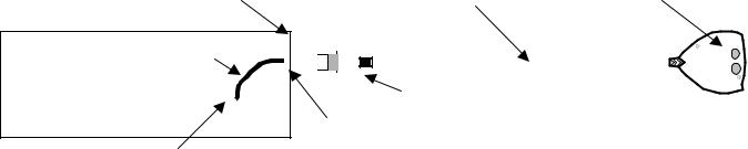
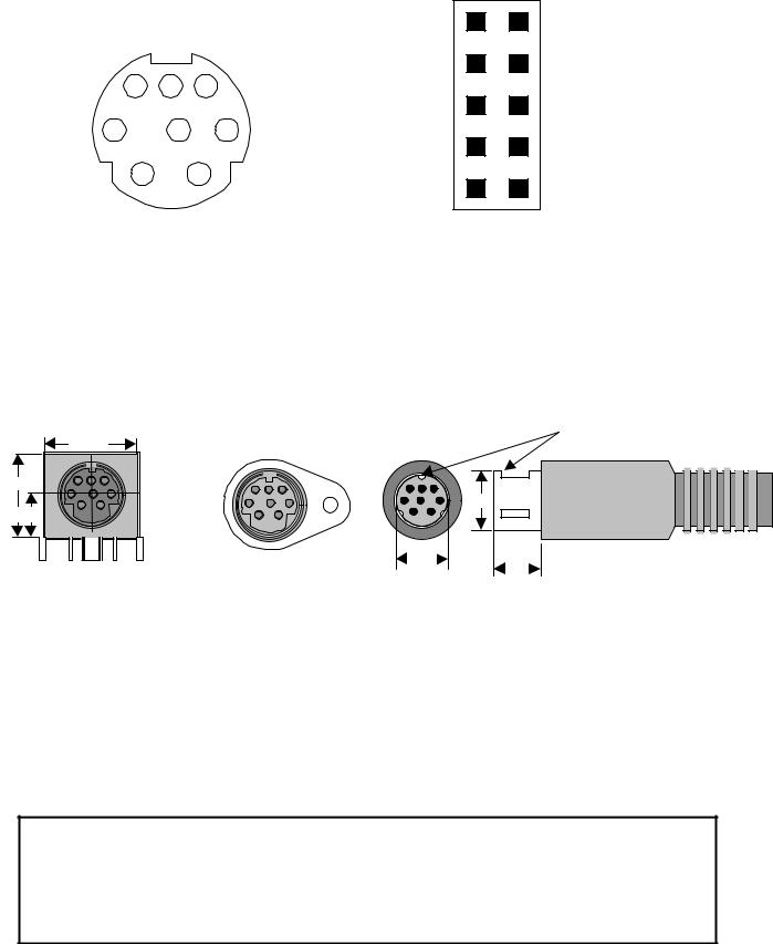
The infrared dongle must use an 8-pin Miniature DIN (MiniDIN-8) plug to connect to the HOST external MiniDIN-8 receptacle. The HOST motherboard PC must use a dual row header connector to connect to the MiniDIN-8 receptacle as shown in figure 2-1. The pin assignments for these connectors are shown in figures 2-2 and 2-3. Figure 2-4 defines the 8-pin MiniDIN receptacle and plug along with recommended manufacturers’ part number. Table 2-1 defines the dongle interface signals. The signal functions depend upon the optical transceiver used by the dongle, and whether single-ended or differential signaling is used.
|
|
PC BACKPANEL |
|
|
|
|
|
|
|
|
|
|
External Cable |
IR TRANSCEIVER |
|
|
|
|
|
|
|
|
|
|
|
|
|
|
|
|
|
|
|
|
|
|
|
||
PC ENCLOSURE |
|
|
|
|
|
|
|
|
|
|
|
|
|
|
|
|
|
||
|
|
|
|
|
|
|
|
|
|
|
|
|
|
|
|
|
|||
|
|
Internal Cable |
|
|
|
|
|
|
|
|
|
|
|
|
|
|
|
|
|
|
|
|
|
|
|
|
|
|
|
|
|
|
|
|
|
|
|
|
|
|
|
MOTHERBOARD |
|
|
|
|
|
|
|
|
|
|
IrDA MiniDIN-8 PLUG |
|
|
|
|
|
|
|
|
|
|
|
|
|
|
|
|
|
|
|
|
|
|
|
|
||
|
|
|
|
|
|
|
|
|
|
|
|
|
|
|
|
|
|
||
|
|
|
|
|
|
|
|
|
|
|
|
|
|
|
|
|
|
||
|
|
|
|
|
|
|
|
|
|
|
|
|
|
|
|
|
|
|
|
|
|
|
|
|
|
|
|
|
|
IrDA MiniDIN-8 RECEPTACLE |
|
|
|
|
|
|
|||
MOTHERBOARD HEADER |
|
|
|
|
|
|
|
|
|
|
|
|
|
||||||
|
|
|
|
|
|
|
|
|
|
|
|
|
|
|
|
|
|||
|
|
|
|
|
|
|
|
|
|
|
|
|
|
|
|
|
|||
Figure 2-1. Infrared dongle connection in a typical desktop PC.
5
|
|
|
|
1 |
|
|
|
|
3 |
8 |
|
7 |
6 |
5 |
5 |
|
|
3 |
7 |
|
2 |
4 |
1 |
|
|
|
|
9
2
4
6
8
10
|
Note : Pins 9 and 10 are reserved and should be |
|
left unconnected. |
Figure 2-2. 8-pin Miniature DIN Receptacle |
Figure 2-3. Motherboard Infrared HEADER |
(Front View) |
(component side view) |
|
Double Row (2.54 x 2.54 [0.100 x |
|
0.100] Centerline). |
|
Standard 3 point keying |
14.0 |
|
12.8 |
|
φ 9.0 |
|
6.5 |
|
φ 8.2 |
ALL DIMENSIONS IN MM |
6.0 |
PCB Receptacle |
Panel Receptacle |
Cable Plug |
|
||
AMP |
: 749179-1 |
AMP |
: 750338-1 |
|
|
Maxconn |
: MMDF-8SNB-4 |
Maxconn |
: MMDV-8 |
Maxconn |
: MMDM-8SB-2 |
Singatron |
: DJ-010-8PS(A) |
Singatron |
: YE-1368A |
Singatron |
: YE-1158A |
CUI Stack |
: SDF-80J |
CUI Stack |
: SD-80SN |
CUI Stack |
: SD-80 |
Figure 2-4. 8-pin Miniature DIN Receptacle & Plug Dimensions and
Recommended Manufacturers’ Part Number.
CAUTION: The MiniDIN-8 receptacle and plug specified for the IrDA dongle connector has the potential to interfere with MiniDIN-8 connectors found on audio/video consumer electronics and Apple’s Localtalk connector. Appropriate warning to the end user is strongly recommended. Use of the IrDA logo on both the receptacle and plug is
strongly recommended to identify the function of the connector and avoid misconnection to similar connectors. Please refer to Appendix A or the ‘IrDA Logo Use and
Guidelines’ document available from IrDA.
6
Table 2-1. Dongle Interface Signals
Signal Name |
Type |
MiniDIN-8 |
HEADER |
Description |
|
|
|
pin # |
pin # |
|
|
|
|
|
|
|
|
IRTX/IRTX+ |
O |
1 |
1 |
- Infrared transmit data for single-ended or |
|
|
|
|
|
differential signaling |
|
|
|
|
|
|
|
IRRX1/IRRX+ |
I |
2 |
7 |
- Infrared receive data for single-ended or |
|
differential signaling |
|||||
|
|
|
|
||
|
|
|
|
|
|
GND |
O |
3 |
3 |
- Ground |
|
|
|
|
|
|
|
VCC |
O |
4 |
4 |
- 5V supply |
|
|
|
|
|
|
|
ID0/IRSL0/IRRX2/IRRX- |
I/O |
5 |
8 |
- Identification signal 0, or |
|
|
|
|
|
- Infrared mode select 0, or |
|
|
|
|
|
- Infrared receive data for transceivers with two |
|
|
|
|
|
RX channels (note 1), or |
|
|
|
|
|
- Infrared receive data for differential signaling |
|
|
|
|
|
|
|
ID1/IRSL1/IRTX- |
I/O |
6 |
2 |
- Identification signal 1, or |
|
|
|
|
|
- Infrared mode select 1, or |
|
|
|
|
|
- Infrared transmit data for differential signaling |
|
|
|
|
|
|
|
ID2/IRSL2/SCLK+ |
I/O |
7 |
5 |
- Identification signal 2, or |
|
|
|
|
|
- Infrared mode select 2, or |
|
|
|
|
|
- Clock for differential serial control interface |
|
|
|
|
|
|
|
ID3/SCLK- |
I/O |
8 |
6 |
- Identification signal 3, or |
|
|
|
|
|
- Clock for differential serial control interface |
|
|
|
|
|
|
|
Reserved |
|
N/A |
9 |
|
|
|
|
|
|
|
|
Reserved |
|
N/A |
10 |
|
|
|
|
|
|
|
Note 1: IRRX2 connects to the high-speed RX channel.
3.0 CABLE CHARACTERISTICS
Two different cables are required in a typical (non ATX) desktop PC implementation to provide infrared connectivity, one internal and one external. These cables are shown in figure 2-1.
3.1 Internal Cable
The internal cable provides for the interconnection between the motherboard IR header and the external connector mounted on the back panel. There are no special requirements for this cable. In most cases a ribbon cable should suffice.
7

3.2 External Cable
A multi-core shielded cable should be used by the dongle to minimize electromagnetic interference. The cable characteristics are given in table 3-1.
SHIELD
 JACKET
TALC
 CONDUCTOR
 INSULATION
Figure 3-1. External cable cross-section.
Table 3-1. External Cable Characteristics
ELECTRICAL
Characteristic Impedance |
|
70 - 120 |
ohm |
|
|
|
|
DC Resistance |
|
200 - 300 ohm / km |
|
|
|
|
|
Capacitance |
|
30 - 90 |
pF / m |
|
|
|
|
MECHANICAL |
|
|
|
|
|
|
|
Conductor |
Minimum Gauge |
28 AWG |
|
|
|
|
|
|
Material |
Copper Stranding |
|
|
|
|
|
4.0 ELECTRICAL SPECIFICATIONS
Table 4-1 provides the electrical characteristics at the external connector. Only the DC characteristics are specified in this document. The signal timings are provided in the controller and transceiver data sheets from the various manufacturers. The timings for the serial interface are provided in the document titled “Recommended Serial Interface for Transceiver Control” available from IrDA.
8
Table 4-1. Electrical Characteristics
Vcc = 5.0V +/- 5%, GND = 0V
Symbol |
Parameter |
Test Conditions |
Min. |
Max. |
Units |
|
|
|
|
|
|
POWER SUPPLY PIN |
|
|
|
|
|
|
|
|
|
|
|
Vcc |
Supply Voltage |
|
4.75 |
5.25 |
V |
|
|
|
|
|
|
Icca |
Supply Average Current |
|
|
300 |
mA |
|
|
|
|
|
|
Iccp |
Supply Peak Current |
(note 1) |
|
600 |
mA |
|
|
|
|
|
|
SINGLE ENDED SIGNALS |
|
|
|
|
|
|
|
|
|
|
|
Vih |
High Level Input Voltage |
|
2.0 |
Vcc+0.5 |
V |
|
|
|
|
|
|
Vil |
Low Level Input Voltage |
|
-0.5 |
0.8 |
V |
|
|
|
|
|
|
Voh |
High Level Output Voltage |
|
2.4 |
|
V |
|
|
|
|
|
|
Vol |
Low Level Output Voltage |
|
|
0.4 |
V |
|
|
|
|
|
|
Ildtx |
Input Load Current, |
0 ≤ Vin ≤ Vcc (note 2) |
|
6 |
mA |
|
(IRTX signal) |
|
|
|
|
|
|
|
|
|
|
Ild |
Input Load Current, |
0 ≤ Vin ≤ Vcc |
|
1.5 |
mA |
|
(all signals except IRTX) |
|
|
|
|
|
|
|
|
|
|
DIFFERENTIAL SIGNALS (EIA-644 Standard) |
|
|
|
||
|
|
|
|
|
|
Vod |
Differential Output Voltage |
RL = 100 ohm |
247 |
454 |
mV |
|
|
|
|
|
|
Vos |
Offset Voltage |
|
1.125 |
1.375 |
V |
|
|
|
|
|
|
Isc |
| Short Circuit Current | |
|
|
24 |
mA |
|
|
|
|
|
|
Iin |
| Input Load Current | |
Vod = 454 mV |
|
5 |
mA |
|
|
|
|
|
|
Vth |
| Input Threshold Voltage | |
|
|
100 |
mV |
|
|
|
|
|
|
Vin |
Input Voltage Range |
|
0 |
2.4 |
V |
|
|
|
|
|
|
Note 1: A current limiting/protection mechanism should be provided on the Vcc line.
Note 2: The input current may be higher during switching due to transmission line effects of the cable.
5.0 DONGLE IDENTIFICATION AND INFRARED MODE SELECTION
The identification scheme described below allows the software to identify the dongle capabilities as well as the type of the infrared transceiver or transceivers being used. This is needed so that the software driver can correctly select the transceiver operational mode.
The identification is performed in two phases due to the limited number of ID signals. These phases are referred to as primary and secondary.
9
5.1 Primary Identification Phase
This phase represents the first step in the dongle identification process. It is used to identify the basic dongle type and, if non-serial transceivers are used, it also identifies the characteristics of the IrDA-Data transceiver. The infrared controller sets the pins 5 through 8 to input mode and reads their logical levels. The encoding listed in table 5-1 below are provided by the dongle on these pins. The dongle uses pull-up or pull-down resistors to drive these pins to the appropriate levels.
Table 5-1. Primary ID Encoding
ID3, ID2, ID1, ID0 |
Basic Dongle Information (notes 1a, 2a) |
|||
|
|
|
|
|
1, |
1, |
1, |
1 |
No dongle connected (note 3a) |
|
|
|
|
|
1, |
1, |
1, |
0 |
IrDA-Data transceiver supports SIR mode only |
|
|
|
|
|
1, |
1, |
0, |
x |
IrDA-Data transceiver is: HP HSDL-1100 or HP HSDL-2100 or TI TSML1100 |
|
|
|
|
or Sharp RY6FD11E (note 4a) |
|
|
|
|
|
1, |
0, |
1, |
1 |
IrDA-Data transceiver is: Vishay-Telefunken TFDS6500 |
|
|
|
|
|
1, |
0, |
1, |
0 |
Reserved |
|
|
|
|
|
1, |
0, |
0, |
1 |
IrDA-Data transceiver is: IBM 31T1100 or Vishay-Telefunken TFDS6000 or |
|
|
|
|
Siemens IRMS/T6400 |
|
|
|
|
|
1, |
0, |
0, |
0 |
IrDA-Data transceiver is: HP HSDL-2300 or HP HSDL-3600 |
|
|
|
|
|
0, |
1, |
1, |
1 |
Infrared transceiver supports Consumer-IR modes only |
|
|
|
|
|
0, |
1, |
1, |
0 |
Infrared transceiver with serial interface and single-ended signaling |
|
|
|
|
|
0, |
1, |
0, |
1 |
Reserved |
|
|
|
|
|
0, |
1, |
0, |
0 |
IrDA-Data transceiver is: Sharp RY5HD01 or Sharp RY5KD01 |
|
|
|
|
|
0, |
0, |
1, |
x |
Reserved |
|
|
|
|
|
0, |
0, |
0, |
x |
Infrared transceiver with serial interface and differential signaling |
|
|
|
|
|
Note 1a: During the primary identification phase the host controller uses single-ended signaling. Differential signaling is used during the secondary identification phase only
if it is supported by the dongle.
Note 2a: It is assumed that all dongles supporting FIR mode (4.0 Mbps) support
MIR mode (576 kbps and 1.152 Mbps) as well.
Note 3a: Weak pull-ups (e.g. 100 kohm) are provided on the infrared controller side on pins 5 through 8 to ensure that these pins will read as logic 1 when no dongle is connected.
Note 4a: The ID0 signal is not available in dongles using IrDA-Data transceivers with two receiver channels. This is because the transceiver drives this signal and therefore its level cannot be controlled by pull-up or pull-down resistors.
Note 5a: When the host software changes the direction of the ID signals from output to input, a minimum delay of 50 us should be allowed before reading the primary ID code. This is to allow the ID signal levels to stabilize.
The 50 us delay does not have any effect on performance since the dongle identification is performed only once, when the infrared driver in the host is first initialized.
10