

Embedded system engineering magazine 2005.06
.pdfDig deeper into DSP at
www.esemagazine.com
Freescale Semiconductor |
Microchip Technology |
Philips Semiconductors |
picoChip Designs |
Research Centre MODULE |
Research Centre Module |
Sensory, Inc. |
|
|
|
|
|
|
|
|
|
MSC812x |
|
|
|
1878BM3 |
NeuroMatrix |
|
|
Quad-Core |
dsPIC30F |
PNX1700 |
picoArray |
Digital Signal |
NM6403 |
RSC-4x |
|
StarCore DSP |
Memory (DSM) |
RISC/DSP Mi- |
Family |
||||
with Ethernet |
|
|
|
SoC |
croprocessor |
|
|
|
|
|
|
|
|
|
|
32/64 |
16-bit |
32-bit |
16 |
64 or 32 |
64 |
8 |
|
|
|
|
|
|
|
|
|
16 |
24-bit |
32-bit |
48 |
128 |
32 or 64 |
8 |
|
|
|
|
|
|
|
|
|
|
|
|
|
|
|
|
|
300/400/500 |
|
|
160MHz * |
|
|
|
|
120Mhz |
500 MHz |
322 proces- |
150 |
40 |
14.3MHz |
||
MHz |
|
|
sors |
|
|
|
|
|
|
|
|
|
|
||
1.1 or 1.2 V |
2.5 to 5.5 V |
1.2V |
1.2V 3.3V |
3.3 and 2.5 |
3.0 to 3.6V |
2.4 - 3.6V |
|
3.3 V I/O |
|||||||
|
|
|
|
|
|
||
NA |
146mA @ |
2.5W - 3W |
5W |
4.2 |
1.6 |
72mW (20mA |
|
30MIPS |
@ 3.6V) |
||||||
|
|
|
|
|
|||
Wait, 375 mA |
SLEEP, 1uA |
|
<1W |
|
|
Idle, 4uA |
|
Stop, 290 mA |
IDLE, 0.6mA |
|
|
|
Sleep, 1uA |
||
|
|
|
|
||||
|
|
|
|
|
|
|
|
M1 SRAM |
|
64K level-1 |
|
|
|
|
|
Flash |
instruction |
|
SRAM |
SRAM |
ROM |
||
(one per core) |
|
||||||
|
|
cache |
|
|
|
|
|
4x224 (896 KB) |
12 Kbytes |
|
8Mbp on chip |
2Mbit |
6Kbit |
64K Bytes |
|
4x224 (896 KB) |
144 Kbytes |
|
|
|
|
128K Bytes |
|
M2 SRAM |
RAM |
16K level-1 |
|
|
|
SRAM |
|
(shared) |
data cache |
|
|
|
|||
|
|
|
|
|
|||
|
|
|
|
|
|
|
|
475 KB |
512 bytes |
|
|
|
|
2.8K Bytes |
|
475 KB |
8 Kbytes |
|
|
|
|
4.8K Bytes |
|
Boot ROM |
EEPROM |
128K level-2 |
|
|
|
|
|
data cache |
|
|
|
|
|||
|
|
|
|
|
|
||
4 KB |
1 Kbyte |
|
|
|
|
|
|
4 KB |
4 Kbytes |
|
|
|
|
|
|
|
|
|
|
|
|
|
|
3 |
3 |
Programmable |
8 parallel |
16 / 20 |
TI C40 I/O |
24 |
|
0 |
N/A |
none |
- |
|
|
0 |
|
0 |
To 16 x 12-bit |
none |
- |
2 |
|
1 |
|
1 |
2 |
Programmable |
- |
|
|
0 |
|
1 |
ENC28J60 |
10/100 on-chip |
- |
|
|
0 |
|
|
|
|
|
|
|
|
|
No |
N/A |
Yes |
- |
Yes |
Yes |
No |
|
|
|
|
|
|
|
|
|
Yes |
N/A |
No |
128MB |
Yes |
Memory: |
Yes |
|
2x64bit |
|||||||
|
|
|
|
|
|
||
Yes |
N/A |
No |
- |
No |
No |
Yes |
|
|
|
|
|
|
|
|
|
System: |
SPI, I2C, CAN, |
|
8 parallel or 4 |
|
|
|
|
AC97/I2S |
PCI |
|
|
|
|||
32/64 bit |
interchip |
|
|
|
|||
Codec |
|
|
|
|
|||
|
|
|
|
|
|
||
|
|
|
|
|
|
|
|
–40 to 105 |
-40 to 125 |
0 to70 |
|
-40 C to 85 |
-60 to 85 |
0 to 70 |
|
0 to 90 |
|
||||||
|
|
|
|
|
|
||
|
|
|
|
|
|
|
|
|
|
|
|
|
|
|
|
No |
Yes |
Yes |
No |
|
|
Yes |
|
No |
Yes |
Yes |
No |
|
|
Yes |
|
No |
Yes |
|
No |
Yes |
Yes |
Yes |
|
No |
Yes |
|
No |
Yes |
Yes |
Yes |
|
Yes |
Yes |
|
No |
Yes |
Yes |
Yes |
|
Yes |
Yes |
|
Yes |
Yes |
Yes |
Yes |
|
No |
Yes |
|
Yes |
Yes |
Yes |
Yes |

<Buyer's Guide>
ESE Magazine June 05
News
DSP development kit for FPGA
ALTERA CORPORATION has announced the availability of a new digital signal processing (DSP) development kit for Stratix II devices. The DSP kit’s development board is based on the Stratix II EP2S180 device, as a platform for developing high-performance FPGA-based DSP applications as well as ASIC and structured ASIC design prototypes.
The kit includes a DSP development board, Quartus II software version 5.0, the newlyreleased DSP Builder version 5.0, DSP system reference designs, and an evaluation version of The MathWorks’ latest MATLAB/Simulink software update. Altera’s DSP Builder tool allows engineers to create hardware designs directly from the Simulink model-based design environment.
www.altera.com/codedsp
Cyclone II development kits
ALTERACORPORATION has also begun shipping Cyclone II development kits, for designers targeting Nios II embedded processor, digital signal
processing (DSP), and PCI designs.
All three Cyclone II development kits combine Altera’s intellectual property (IP), boards, and development software. Each kit includes a Cyclone II development board, a CD containing documentation and reference designs, a power supply, a USBBlaster download cable, and other cables. The kits also ship with Altera’s Quartus II design software and a suite of interface IP cores.
The DSP Development Kit, Cyclone II Edition is for the dedicated DSP circuitry in the Cyclone II devices. It has TI’s ADS5500 of analog-to-dig- ital (A/D) converters, the DSP Development Kit, Cyclone II Edition includes the Cyclone II DSP development board, the DSP Builder development tool, Quartus II development software, The MathWorks MATLAB/Simulink evaluation software, evaluation IP cores, system reference designs and labs, as well as power supplies, cables, and documentation.
www.altera.com
DSP FPGAs
Dig deeper into DSP at
www.esemagazine.com
Company name |
|
|
Semicon- |
|
|
Altera |
Altera |
Lattice ductor |
|
|
|
|
|
|
DSP family designation |
Stratix II |
Cyclone II FPGAs |
Lattice ispECP-DSP |
|
|
|
|
|
|
|
|
|
|
|
Bus width (bits) |
Programmable |
Programmable |
Programmable 9x9, |
|
18x18, 36x36. |
||||
|
|
|
||
|
|
|
|
|
Instruction width (bits) |
Programmable |
Programmable |
|
|
|
|
|
|
|
Clock speed: (MHz) |
450MHz for Stratix II DSP |
250MHz for Cyclone II |
250Mhz |
|
Block |
Multiplier |
|||
|
|
|||
|
|
|
|
|
Voltage (V) |
|
|
1.2V |
|
Power used: Operat- |
|
|
Application dependant |
|
ing (Max) |
|
|
||
|
|
|
||
|
|
|
|
|
Power used: Power- |
|
|
No Power down mode |
|
down modes |
|
|
||
|
|
|
||
|
|
|
|
|
On-chip memory |
|
|
|
|
Type (1) |
|
|
Embedded Block RAM |
|
Min |
|
|
18Kbits |
|
Max |
|
|
535Kbits |
|
Type (2) |
|
|
Distributed Memory |
|
Min |
|
|
|
|
Max |
|
|
131Kbits |
|
Type (3) |
|
|
|
|
Min |
|
|
|
|
Max |
|
|
|
|
I/O and Interfaces |
|
|
|
|
Serial (number) |
Not Applicable |
Not Applicable |
496 Max |
|
USB (number) |
Not Applicable |
Not Applicable |
|
|
A/D (number) |
Not Applicable |
Not Applicable |
|
|
UART (number) |
Not Applicable |
Not Applicable |
|
|
Ethernet (number) |
Not Applicable |
Not Applicable |
|
|
|
|
|
|
|
Memory interface: |
Yes |
Yes |
Yes |
|
- DDR |
||||
|
|
|
||
|
|
|
|
|
Memory interface: |
Yes |
Yes |
Yes |
|
-SRAM |
||||
|
|
|
||
|
|
|
|
|
Memory interface: |
Yes |
Yes |
Yes |
|
-Flash |
||||
|
|
|
||
|
|
|
|
|
|
|
|
|
|
Buses |
A variety of industry |
A variety of industry |
|
|
standard buses |
standard buses |
|
||
|
|
|||
|
|
|
|
|
|
|
|
|
|
Temperature Range |
Commerial 0 to 70 |
Commerial 0 to 70 |
|
|
degrees C, Industrial -40 |
degrees C, Industrial -40 |
0-85 |
||
(Min/Max) oC |
||||
to +85 degrees C |
to +85 degrees C |
|
||
|
|
|||
|
|
|
|
|
Application area |
|
|
|
|
Consumer |
Yes |
Yes |
Yes |
|
Portable/hand held |
Yes |
Yes |
No |
|
Industrial |
Yes |
Yes |
Yes |
|
Automotove |
Yes |
Yes |
Yes |
|
Aerospace/defence |
Yes |
Yes |
Yes |
|
Telecomms |
Yes |
Yes |
Yes |
|
Computing |
Yes |
Yes |
Yes |
BG6

Company name
DSP family designation
Target: ASIC or FPGA?
Bus width (bits)
Instruction width (bits)
Clock speed: (MHz)
Voltage (V)
Power used: Operating (Max)
Power used: Powerdown modes
On-chip memory
Type (1)
Min
Max
Type (2)
Min
Max
Buses
Temperature Range (Min/Max) oC
Application area
Consumer
Portable/hand held
Industrial
Automotove
Aerospace/defence
Telecomms
Computing
Dig deeper into DSP at
www.esemagazine.com
Morpho Technologies |
|
Research Centre Module |
|
StarCore LLC |
|
StarCore LLC |
|
Tensilica, Inc. |
MSx |
|
NMC - 64-bit NeuroMa- |
|
SC1000 family |
|
SC2000 family |
|
Xtensa LX |
|
|
|
|
|||||
|
|
trix RISC/DSP Core |
|
|
|
|
|
|
ASIC |
|
ASIC |
|
ASIC |
|
ASIC |
|
ASIC/FPGA |
|
|
|
|
|||||
|
|
|
|
1x128 program, 1x32 |
|
1x128 program, 1x32 |
|
32, 64 or 128 (configu- |
|
|
|
|
|
|
|||
|
|
|
|
|
|
|||
256 |
|
64 |
|
program address, 2x64 |
|
program address, 2x64 |
|
|
|
|
|
|
rable) |
||||
|
|
|
|
data, 2x32 data address |
|
data, 2x32 data address |
|
|
32 |
|
32 or 64 |
|
Variable between 16 |
|
Variable between 16 |
|
24, 32 or 64 (selectable) |
|
|
and 128 |
|
and 128 |
|
|||
|
|
|
|
|
|
|
||
|
|
|
|
SC1200: 340-470; |
|
SC2200: 360-500; |
|
500 MHz in 90 nm |
400 |
|
123 |
|
SC1400: 330-450; (90 |
|
SC2400 350-470; (90 nm |
|
|
|
|
|
|
technology |
||||
|
|
|
|
nm High Perf process) |
|
High Perf process) |
|
|
|
|
|
|
Variable depending on |
|
Variable depending on |
|
Varies with process |
1.2 |
|
|
|
application requirements |
|
application requirements |
|
|
|
|
|
|
& process selected |
|
& process selected |
|
choice |
|
|
|
|
|
|
|
||
150 mW (90 nm) |
|
|
|
Process-dependent |
|
Process-dependent |
|
Varies with process |
|
|
|
|
|
choice |
|||
|
|
|
|
|
|
|
|
|
10 mW (90 nm) |
|
|
|
Process-dependent |
|
Process-dependent |
|
Varies with process |
|
|
|
|
|
choice |
|||
|
|
|
|
|
|
|
|
|
|
|
|
|
SRAM or ROM, or any |
|
SRAM or ROM, or any |
|
User-defined local |
|
|
|
|
|
|
|||
SRAM |
|
SRAM |
|
combination, unified |
|
combination, unified |
|
|
|
|
|
|
memory, Cache |
||||
|
|
|
|
memory |
|
memory |
|
|
|
|
|
|
|
|
|
||
40 K bytes |
|
2Mbit |
|
0 |
|
0 |
|
0 |
128 K bytes (recom- |
|
8Mbit |
|
Limited only by the |
|
Limited only by the |
|
32 KB |
mended) |
|
|
address space (4GB) |
|
address space (4GB) |
|
||
|
|
|
|
|
|
|||
|
|
|
|
|
|
|
|
Up to 2 instruction me- |
|
|
|
|
|
|
|
|
mory RAMS and 2 data |
|
|
|
|
|
|
|
|
RAMS per Xtensa LX |
|
|
|
|
|
|
|
|
0 |
|
|
|
|
|
|
|
|
256 KB |
AMBA AHB, other |
|
|
|
AHB 2.0, AMBA Lite |
|
AHB 2.0, AMBA Lite |
|
all (AMBA, Sonics, |
|
|
|
|
|
||||
|
|
|
|
|
||||
|
|
|
|
|
IBM’s CoreConnect) |
|||
|
|
|
|
|
|
|
|
|
NA |
|
|
|
Process-dependent (nor- |
|
Process-dependent (nor- |
|
all |
|
|
|
|
|
||||
|
|
|
|
|
||||
|
|
|
|
mally -40C to +125C) |
|
mally -40C to +125C) |
|
|
Yes |
|
Yes |
|
Yes |
|
Yes |
|
Yes |
|
|
|
|
|||||
|
|
|
|
|||||
Yes |
|
|
|
Yes |
|
Yes |
|
Yes |
Yes |
|
Yes |
|
Yes |
|
Yes |
|
Yes |
Yes |
|
Yes |
|
Yes |
|
Yes |
|
Yes |
Yes |
|
Yes |
|
No |
|
No |
|
Yes |
Yes |
|
Yes |
|
Yes |
|
Yes |
|
Yes |
Yes |
|
Yes |
|
Yes |
|
Yes |
|
Yes |
|
|
|
|
|
|
|
|
|
<Buyer's Guide>
ESE Magazine June 05
BG7
<Buyer's Guide>
ESE Magazine June 05
Suppliers |
|
Dig deeper into DSP at |
||||
|
www.esemagazine.com |
|||||
|
Company name |
Sales contact |
Web address |
UK Distributor name |
||
|
|
|
|
|
|
|
|
Altera |
Angela Lovegrove |
alovegro@altera.com |
www.altera.com |
Arrow Electronics UK |
|
|
|
|
|
|
|
|
|
Analog Devices |
Andrew Lanfear |
andrew.lanfear@analog.com |
www.analog.com |
Abacus Polar Holdings / Arrow Electronics GB / |
|
|
Avnet Silica / Farnell INONE Electronics Comp |
|||||
|
|
|
|
|
||
|
Freescale Semiconductor |
|
|
www.freescale.com |
|
|
|
|
|
|
|
|
|
|
Lattice Semiconductor |
Jackie Black |
jackie.black@latticesemi.com |
www.latticesemi.com |
WBC, Eurodis, Arrow |
|
|
|
|
|
|
|
|
|
Microchip Technology |
|
euro.enquiry@microchip.com |
www.microchip.com |
Arrow Electronics, Farnell In One, Future Electron- |
|
|
|
ics, Unique Memec |
|
|||
|
|
|
|
|
||
|
Morpho Technologies |
Tom Eichenberg |
tome@morphotech.com |
www.morphotech.com |
NA |
|
|
Philips Semiconductors |
|
|
www.semiconductors.com |
Various, listed at www.semiconductors.philips.com |
|
|
|
|
|
|
|
|
|
picoChip Designs |
Rupert Baines |
Rupert Baines |
www.picochip.com |
- |
|
|
|
|
|
|
|
|
|
Research Centre Module |
Ekaterina Lazutkina |
sales@module.ru |
www.module.ru |
|
|
|
|
|
|
|
|
|
|
Sensory, Inc. |
Sensory Sales |
sales@sensoryinc.com |
www.sensoryinc.com |
Premier Microelectronics Europe Ltd |
|
|
|
|
|
|
|
|
|
StarCore LLC |
Guenter Zeisel |
guenter.zeisel@sarcore-dsp.com |
www.starcore-dsp.com |
N/A |
|
|
|
|
|
|
|
|
|
Tensilica, Inc. |
Tim Penhale-Jones |
tim@tensilica.com |
www.tensilica.com |
N/A |
|
|
|
|
|
|
|
|
Distributors
Abacus Polar Holdings
m www.abacus.co.uk
2 +44 (0) 1525 8580001 t express@abacus.co.uk
Arrow
m www.arrowne.com
2 +44 (0) 1279 441144 t cjenkins@arrowuk.com
Avnet Silica
m www.avnet.com
2 +44 (0) 1438 788310
t silica.stevenage@avnet.com
Eurodis
m www.eurodisuk.com
Farnell
m www.farnellinone.com t sales@farnellinone.com
Future Electronics
m www.futureelectronics.com
Premier Microelectronics Europe Ltd
m www.premmicro.co.uk
2 David Rix
t david.rix@premmicro.co.uk.
Unique Memec
m www.unique.uk.memec.com
t microchipsales@unique.uk.memec.com
WBC
t www.wbc-europe.com
Key
m Website
2 Phone number / Contact t Email address
BG8
Why use an RTOS on DSP’s ?
<Written by> David Kalinsky, Enea Embedded Technology </W>
Deterministic timing may require that a DSP needs to use an RTOS.
REAL-TIME EMBEDDED DSP based systems are tightly constrained environments in which memory and processing power are limited. In addi-
tion, they must provide their services within strict time deadlines to their users and to the surrounding world with which the systems interface. It is these memory, speed and timing constraints that dictate the differences between basic operating systems and schedulers on the one hand, and real-time operating systems on the other hand.
Basic issues
The key difference between schedulers and realtime operating systems is the need for “deterministic” timing behavior in the real-time operating systems. Formally, “deterministic” timing means that operating system services consume known and expected amounts of time. In theory these service times could be expressed as mathematical formulas that must be strictly algebraic and have no random timing components.
For basic OS’s and schedulers deterministic timing behavior was simply not a design goal while real-time operating systems often go a step beyond basic determinism. For many kernel services, these operating systems offer constant loadindependent timing: In other words, the algebraic formula is as simple as: T(message_send) = constant, irrespective of the length of the message to be sent, or other factors such as the num-
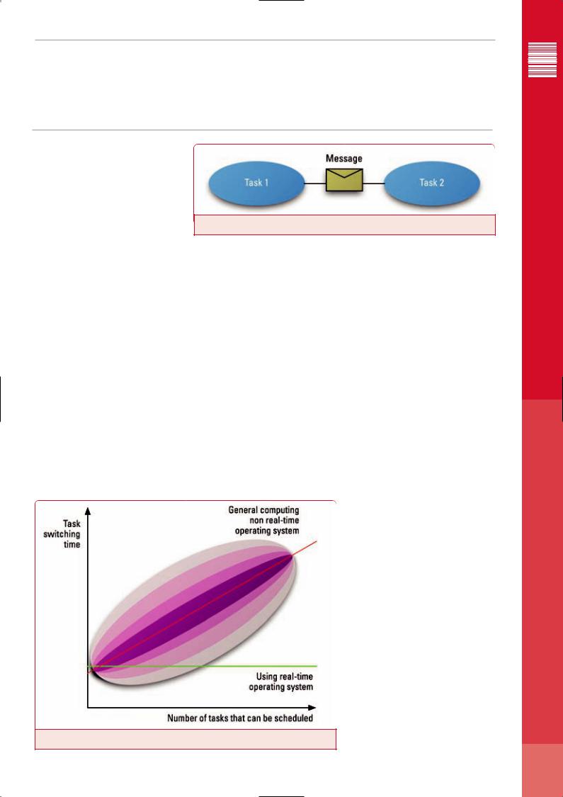
Figure 2: Intertask message communication
bers of tasks and queues and messages being managed by the real-time operating system.
Fixed-time task switching
Task switch timing is of interest when evaluating an operating system. A simple (non-real- time) operating system might do task switching only at timer tick times, which might for example be a millisecond apart. Then if the need for a task switch arises anywhere within a millisecond timeframe, the actual task switch would occur (non-deterministically) only at the end of the current millisecond.
In more sophisticated preemptive task schedulers, the scheduler may need to search through arrays of tasks to determine which task should be made to run next. If there are more tasks to search through, the search will take longer (nondeterministically). Such searches are often done by general-computing operating systems, thus making them non-deterministic. Real-time operating systems, on the other hand, avoid such
searches by using incrementally updated tables that allow the task scheduler to identify the task that should run next in a fixed-time fashion.
These two types of timing behavior for task switching can be seen in Figure 1.
In this figure, we see that for a general-com- puting (non-real-time) operating system, the task switching time generally rises as a software system includes more tasks that can be scheduled. However, the actual time for a task switch is not the time shown by the dashed red line. Instead, in any given task switch instance, it might be well above or well below the time shown by the dashed red line. The colored regions surrounding the dashed red line simply show the statistical probabilities of the actual task switch time being that far above or below the dashed red line.
On the other hand, the horizontal green line shows the task switching time characteristic of a real-time operating system. It is constant, independent of any load factor such as the number of tasks in a software system.
Please note that in some instances, such as the leftmost area of the graph, the task switching time might in some instances be quicker for a generalcomputing non-real-time operating system, than for a real-time operating system. This does not detract from the appropriateness of a real-time operating system for real-time embedded applications. For, in fact, the term “real-time” does not mean “as fast as possible”; but rather “real-time” demands consistent, repeatable, known timing performance. Although a non-real-time operating system might do some faster task switching for small numbers of tasks, it might equally well introduce a long time delay the next time it does the same task switch. Typically, the real-time operating system will exhibit task switching times much faster than its non-real-time competitor when the number of tasks grows above 5 or 10.
Dynamic memory allocation
Determinism of service times is also important in
Figure 1: Task switching timing the area of dynamic allocation of RAM memory. Many general-computing non-real-time operating >>
<Feature>
ESE Magazine June 05
25

</Feature>
ESE Magazine Mar/April 04
<<systems offer memory allocation services from what is termed a “Heap”. The famous “malloc” and “free” services work from a heap. However, heaps suffer from a phenomenon called “External Memory Fragmentation” that may cause the heap services to degrade. This fragmentation problem can be solved by so-called “garbage collection” (defragmentation) software. Unfortunately, “garbage collection” algorithms are often wildly non-deterministic – injecting randomly-appearing random-duration delays into heap services.
Real-time operating systems, on the other hand, avoid “garbage collection” and its timing consequences, by offering non-fragmenting memory allocation techniques instead of heaps. For example, the “Pools” memory allocation mechanism allows application software to allocate chunks of memory of a number of sizes,
while totally avoiding external memory fragmentation. Memory is allocated from a pool with deterministic, often constant, timing.
Message passing
Intertask message communication is another area where different kinds of operating systems show different characteristics. See Figure_2. Most operating systems actually copy messages twice as they transfer them from task to task. The first copying is from the message-sender task to an operating system-owned “secret” area of RAM memory; and the second copying is from the operating system’s RAM area to the message-receiver task. Clearly this is non-deterministic in its timing, as these copying activities take longer as message length increases.
An approach that avoids this non-determin-
ism and also accelerates performance, is to have the operating system copy a pointer to the message and deliver that pointer to the messagereceiver task without moving the message contents at all. In order to avoid access collisions, the operating system then needs to go back to the message-sender task and obliterate its copy of the pointer to the message. For large messages, this eliminates the need for lengthy copying and eliminates non-determinism.
Often DSP’s come with their own scheduler or basic OS and for many applications these may be more than adequate. However, when used in high performance and mission critical systems, using an RTOS can provide an important platform for developing robust and responsive code.<Ends>
www.enea.ccom
Using a “DSP-free” design for VOIP-enabled end-points
<Written by> David Brown and Michael Ward, Trinity Convergence </W>
While ever-increasing volume demands help to drive some economies of scale, OEMs and ODMs are also looking to minimize product costs without sacrificing features or call quality.
|
OIP END-POINTS have been tradi- |
Continued improvements in the computing |
peripherals needed for VoIP (such as an Ethernet |
||||
|
tionally designed using a “tandem |
power of general-purpose applications processors |
MAC, an audio codec, a keypad input, and an LCD |
||||
|
processor” architecture, which includes |
now allow the voice processing function to be |
driver), a product designed with a DSP-free archi- |
||||
|
a general-purpose applications |
moved from the DSP to the applications processor |
tecture can achieve the highest level of cost, size, |
||||
Vprocessor and a DSP (Figure 1). The DSP handles |
itself. With such a “DSP-free” approach (Fig 3) cost |
and power consumption savings. |
|||||
the |
packet |
voice |
processing |
(voice |
savings are realized through the removal of the |
Applications processor |
|
encode/decode, tone generation and detection, |
DSP device. This also results in a reduced footprint |
||||||
echo cancellation, noise reduction, etc.), while |
and lowers overall power consumption. In addition, |
In selecting a suitable applications processor for |
|||||
the applications processor manages the VoIP call |
developers only need to work with a single devel- |
a DSP-free end-point design, a number of fea- |
|||||
control protocol and user interface. This architec- |
opment environment and tool-chain, which pro- |
tures need to be considered: |
|||||
ture has a number of drawbacks when attempting |
vides time-to-market gains through reduced design |
|
|
||||
to address the design requirements of high-vol- |
cycles and the ability to more rapidly and easily |
CLOCK SPEED: The processor must run fast |
|||||
ume, low-cost VoIP end-points. For example: the |
debug the product while in development. With the |
enough to handle worst-case VoIP scenarios, |
|||||
need for both an applications processor and a |
availability of highly integrated applications |
which are different for each end-point design, and |
|||||
DSP adds cost to the overall product; two discrete |
processors that contain both the processor and the |
are heavily dependent upon the type of processing >> |
|||||
devices have a larger footprint than a single |
|
|
|
||||
device; and the tandem processor architecture |
|
|
|
||||
increases the overall power consumption. |
|
|
|
|
|||
|
Silicon manufacturers have responded to these |
|
|
|
|||
challenges through the development of SoC archi- |
|
|
|
||||
tectures in which the general-purpose applications |
|
|
|
||||
processor and the DSP are combined within the |
|
|
|
||||
same physical device package or on a single piece |
|
|
|
||||
of silicon (Fig 2). This partially solves the physical |
|
|
|
||||
size and power issues, but does not fully address |
|
|
|
||||
the cost . Also, the nature of VoIP-enabled product |
|
|
|
||||
design favors development of devices with an even |
Figure 1: Traditional VoIP "Tandem Architecture" |
|
|
||||
smaller footprint and lower power. |
|
|
|
||||
|
|
|
|
||||
26

</Feature>
ESE Magazine June 05
Figure 2: Traditional VoIP "Tandem Architecture" in SoC Form
Figure 3: VoIP "DSP-free" Architecture
<< that the end-point must handle. For example, the |
INTEGRATED PERIPHERALS: Applications |
VoIP component is greatly influenced by the audio |
processors with integrated peripherals enhance |
encoding and decoding standards that must be |
cost savings and simplify VoIP end-point design. |
supported (more complex coders require more pro- |
For example, on-chip Ethernet MACs and audio |
cessing power), and by the complexity of the user |
codecs eliminate external discrete devices, which |
interface. In a multi-function device, sufficient pro- |
reduces chip count and power consumption. |
cessing power must be available to run the most |
Adding support for keypad input and display further |
complex scenario, such as simultaneously sup- |
simplifies end-point design and implementation. |
porting a VoIP call and an Internet browser. |
Audio interfaces for VoIP must be able to drive |
|
data in small blocks to minimize latency and delay |
“DSP-LIKE” EXTENSIONS: VoIP processing |
through the system. Many audio drivers written for |
relies heavily on numerically intensive operations |
entertainment applications, such as music players, |
that DSPs are optimized to execute. VoIP media pro- |
buffer data to ensure a smooth stream. This |
cessing in a DSP-free architecture can be further |
approach is not suitable for VoIP, were frequent |
enhanced through the use of applications proces- |
reads and writes to short buffers are needed. |
sors that support media processing extensions. |
|
For example, the ARM926EJ-S core of ARM |
POWER MANAGEMENT: Battery life in a |
Ltd. includes instruction set extensions that are |
portable device can be maximized by having the |
highly flexible and can be used to optimize virtual- |
VoIP application placed in a low-power, or |
ly any type of media processing. Using the ‘E’ |
“snooze,” mode when there are no calls active. |
extensions of the ARM926EJ-S reduces the clock |
To accomplish this, software must be written in |
cycles required to execute a typical voice encoder |
such a way that an incoming call request (using |
by as much as 20 percent, when compared to exe- |
SIP or H.323) or a keypad press will quickly re- |
cution on an ARM9 series core without the ‘E’ |
activate the device to start handling voice data. |
extensions. This saving in clock cycles translates to |
Such techniques as disabling audio peripherals |
either a lower clock speed and increased battery |
and reducing clock speed can further enhance |
life, or additional processing power for the remain- |
battery life when the device is in snooze mode. |
der of the application. To put this in context, a typ- |
Porting software |
ical G.729AB codec optimized with the DSP exten- |
|
sion instructions can save approximately 5 MHz |
The voice codecs and other media processing uti- |
compared to even a well-optimized implementa- |
lized by VoIP are typically designed for efficient |
tion of an architecture without these instructions. |
execution on a DSP in a tandem processor archi- |
This gain is magnified when implementing a more |
tecture. Migrating these compute-intensive oper- |
complex wide-band codec, such as G.722.2, where |
ations to an applications processor, which has a |
approximately 20 MHz can be saved through a DSP |
very different architecture and instruction set |
extension-based implementation. |
than a DSP, requires great care and expertise if |
an optimal solution is to be created. In fact, most voice coders used in VoIP today will not run in real time on a 100 MHz applications processor if the raw ‘C’ model for the vocoder is simply compiled and executed. In addition to this challenge, a tandem processor architecture physically separates voice processing from the management and user applications. With all of these functions merged onto a single device, care must be taken to control the overall system priorities to address the real-time nature of the voice processing.
Efficient coding that squeezes the best from an applications processor’s individual architecture is essential if a complex task such as VoIP is to run in real time. All elements of a processor’s architecture, from best use of the pipeline to elimination of unnecessary instructions and parallelism (where available), must be employed to create useable VoIP software.
Code generation tools for applications processors have advanced significantly in the last five years, but it is still necessary to write assembly code to create an ultra-efficient implementation. Although coding in assembly is a slow and specialized task, it is the most effective way to create and optimize the implementation of media processing elements of VoIP for an applications processor. Implementing the control part of VoIP (e.g., the SIP or H.323 call control stack and user interface) does not require the same level of hand-crafted optimization, and a ‘C’ implementation of these elements is acceptable. By exposing a suitable ‘C’ Application Program Interface (API) to allow control of the media processing elements, development can be partitioned into two parts: creating the real-time VoIP components, and creating the user application (which provides the majority of the user experience in each endpoint). This division allows developers who are experienced in creating the user experience to focus on that part of the end-point, and also allows the complex VoIP media processing software to be re-used in a range of implementations.
Future of DSP-free VoIP
Numerous OEMs and ODMs have adopted DSPfree techniques to develop VoIP end-points with sophisticated GUIs, video telephony services, and complex voice-channels. As Moore’s Law continues to drive the availability of faster, smaller and cheaper applications processors, even more sophisticated services will be supported, building upon today’s foundation of VoIP functionality. These services will include increased channel counts for voice-enabled residential gateways (enabling ultra-low-cost residential IP-PBXs), continually higher fidelity audio with higher levels of compression than exists today, and even the ability to move full-motion video fully onto the applications processor without the need for an acceleration IP block. <Ends>
www.trinityconvergence.com
28

Main photo courtesy of: www.news.navy.mil
MISSION POSSIBLE.
Wright Controls Embedded Computing, we know that reliability and longevity are a critical part of your embedded system. That’s why we design, integrate and test every product we make to ensure that they’ll perform in all kinds of environments, even those where service and support are nearly impossible.
That’s why you should rely on Curtiss-Wright to minimize risk and maximize performance in your mission-critical embedded components and systems.
And that’s The Power Within.
Dy 4 Systems | Peritek | Primagraphics | Synergy | Systran | VISTA Controls
www.cwcembedded.com
</Feature>
ESE Magazine June 05
The need for high-level graphical system design
<Written by> Shelley Gretlein, National Instruments </W>
Graphical methods are a way to improve productivity and time to market.
IN TODAY’S economy, products must the market more quickly than ever combining more technology in a single device, resulting in increased
design and test complexity. Traditional, lowlevel design tools have not kept pace with this increasing complexity, delivering only gradual incremental improvements over the last decade. The key for achieving an order of magnitude improvement is using more intuitive, higherlevel tools. Higher-level graphical paradigms for embedded development are necessary because of the technical limitations with traditional textbased programming environments for system design, which:
●Say little or nothing about concurrency and time
●Typically express concurrency with complex threads, monitors and semaphores
●Limit re-use potential
In order to address these gaps, graphical programming languages are emerging as the answer.
Gene Frantz, Senior Fellow, Texas Instruments states, “As our devices grow in capabilities and sophistication, the role of graphical, system-level design and development tools will continue to increase in importance.”
Digital Signal Processing
Graphical programming is becoming a viable and prevalent solution especially in embedded areas of rapid growth that need to be accessible by many more people – not only embedded programmers but also domain experts, such as scientists and engineers. For example, there is a technological shift in the electronics, automotive and scientific industries to a new era driven by connectivity and multimedia, where digital signal processing (DSP) technology is at the heart. We, as consumers, benefit from this focus on DSP everywhere from videophones to music players and automobile telematics to medical devices. In order for DSP technology to continue proliferation, it is critical that the tools needed to exploit the technology become accessible to the masses.
High-level tools combined with new technology are delivering just that: DSP design for the masses. The new National Instruments LabVIEW
DSP Module offers an integrated graphical programming tool with plug-and-play functionality, helping you create DSP-based applications in hours or even minutes. Ensuring an intuitive and simplified development and design process, the LabVIEW DSP Module does not require any C programming skills or understanding of peripherals because the LabVIEW graphical code compiles directly to the DSP hardware, markedly decreasing the learning curve.
This simplified tool chain empowers you to remain the domain expert whether in math, measurements, or control and still benefit from the ability to run a LabVIEW application in silicon without requiring additional low-level, targeting tools.
LabVIEW DSP module
The NI LabVIEW DSP Module is a fully-featured graphical DSP design tool based on the LabVIEW graphical programming environment that can be used to create real time embedded applications. The National Instruments LabVIEW DSP Module for NI SPEEDY-33 and Texas Instruments C6711 and C6713 DSKs helps you design, prototype and deploy DSP systems through an easy-to-use, interactive graphical environment. There are a host of features that make LabVIEW DSP an ideal tool for development of DSP systems:
●Easy-to-use graphical programming environment
●Direct access to digital and analogue I/O lines of DSP target
●Developing stand-alone DSP applications easily
●Seamless integration of digital filters
●Hundreds of built-in analysis and development functions
●Modularity of code for reuse in future designs
●Easy-to-build, interactive GUIs for real-time interaction
●Code portability to multiple DSP targets (NI SPEEDY-33, TI C6711 or C6713 DSKs)
Until now, experienced DSP design engineers, students learning signal processing and DSP enthusiasts have all faced many challenges in quickly building DSP systems. Graphical pro-
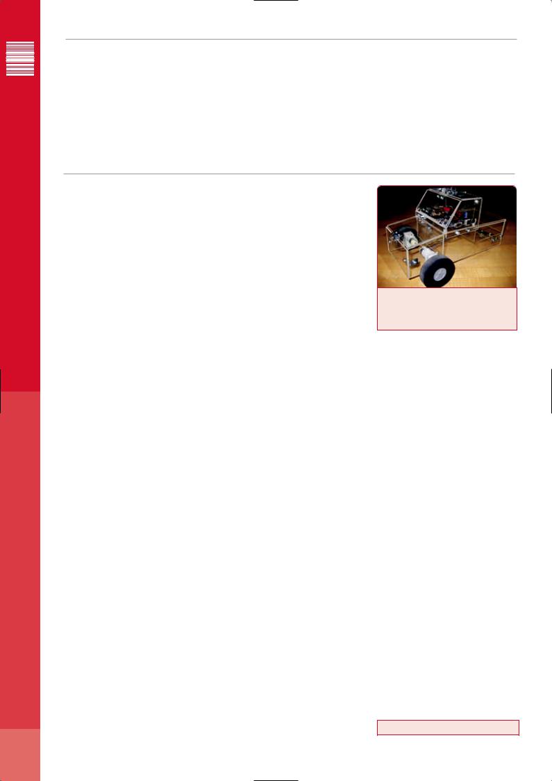
Figure 1: Students Hoyt McMillan, Lorne Liechty, Sander Ray and Justin Prochaska University of Texas A&M, built the Agg-NI Bot using LabVIEW DSP Module.
gramming tools such as LabVIEW DSP Module abstract the implementation details and facilitate rapid DSP application prototyping and deployment. The intuitive graphical environment allows the novice user to learn concepts quickly.
For example, a team at the University of Texas A&M in College Station, Texas recently developed a robot using LabVIEW DSP Module. They were able to quickly and easily develop the embedded code because of the intuitive interface
– LabVIEW DSP Module only requires the code needed for the DSP, students do not have to waste time learning syntax details for communication or debugging, it is all built-into the LabVIEW DSP Module. The experience taught the students valuable and in-depth embedded programming techniques, including acoustic phase detection, PWM control, infared communication and fundamental signal processing – much more than could be developed in the same amount of time with traditional, text-based DSP tools.
Graphical programming for DSPs helps students and professors develop DSP applications faster by creating object code directly from a block diagram. The LabVIEW DSP Module provides a hands-on experiential environment for learning DSP concepts. The students get to experience real world phenomena, which help connect the theory to the real world and reinforce the importance of DSPs. The savings in design and development time, the maintainability advantages and the self-documenting nature of graphical programming will make teaching and learning DSP concepts easier and more fun. <Ends>
www.ni.com
30