

Fang F.Lightweight floating-point arithmetic.Case study of IDCT
.pdfRadix |
Area (um2) |
Delay (ns) |
|
|
|
2 |
8401 |
10.21 |
|
|
|
16 |
7389 (-12%) |
8.48 (-17%) |
|
|
|
Table 8 (a) Comparison of radix 2 and radix 16 – FP adder
Radix |
Area (um2) |
Delay (ns) |
||
|
|
|
|
|
2 |
7893 |
5.8 |
|
|
|
|
|
|
|
16 |
11284 |
(+43%) |
6.62 |
(+14%) |
|
|
|
|
|
Table 8(b)Comparison of radix 2 and radix 16 –FP multiplier
From the table, it is clear that radix-16 is not always better than radix-2. In a certain application, if there are more adders than multipliers, then radix-16 is a better choice than radix-2. In our IDCT structure, there are 29 adders and 11 multipliers. Therefore, radix-16 is chosen for the implementation of IDCT.
Combining all the optimization strategies in this section, the final 15-bit radix-16 FP adder and multiplier are compared with the IEEE-standard compliant single-precision FP adder and multiplier in Table 9. By reducing the bit-width and simplifying the rounding/shifting/exception handling, the power consumption of FP arithmetic unit is cut down to around 1/5 of the IEEEstandard FP unit.
Further optimization can be conducted in two directions. One is low-power design approach. As proposed in [16], triple data path in FP adder structure can reduce the power delay product by 16X. The other is transistor level optimization. Shifter and multiplexor designed in transistors are much smaller and faster than those implemented as logic gates[14, 17].
Data format |
Area (um2) |
Delay (ns) |
Power(mw) |
|
|
|
|
Lightweight |
10666 |
5.67 |
16.5 |
|
|
|
|
IEEE-standard |
51830 |
14.5 |
100.1 |
|
|
|
|
Table 9(a) Comparison of lightweight FP and IEEE FP – adder
Data format |
Area (um2) |
Delay (ns) |
Power(mw) |
|
|
|
|
Lightweight |
5206 |
7.49 |
6.9 |
|
|
|
|
IEEE-standard |
19943 |
21.7 |
29.3 |
|
|
|
|
Table9(b)Comparison of lightweight FP and IEEE FPmultiplier
6. Implementation of IDCT
IDCT performs linear transform on an 8-input data set. The algorithm developed in [18] uses minimum resources –11 multiplications and 29 additions – to compute a one dimension IDCT (Fig. 20)
x7 |
C4 |
C6/C4 |
C5 |
y5 |
|
x5 |
|
|
|
y2 |
|
x3 |
|
C2/C4 |
C7 |
y4 |
|
x1 |
1/C4 |
|
|
y3 |
|
C4 |
C6/C4 |
C3 |
|||
x6 |
y6 |
||||
|
|
|
|||
x4 |
|
|
|
y1 |
|
x2 |
|
C2/C4 |
C1 |
y7 |
|
|
|
|
|||
x0 |
|
|
|
y0 |
Ci = |
1 |
x |
y-x |
x |
C |
C*x |
x |
y+x |
|
|
y |
y |
|||||
|
iπ |
y |
y+x |
|
|
|
2 cos |
|
Butterfly |
|
16 |
|||
|
|||
|
|
||
|
|
Fig. 20 Structure of IDCT |
6.1 Optimization in butterfly
In the architecture of IDCT, there are 12 butterflies and each one is composed of two adders. Because these two adders have the same inputs, some operations such as pre-alignment and negation can be shared. Further, in the butterfly structure, normalization and leading-one detection can be separated into two paths and executed in parallel, which reduce the timing critical path.
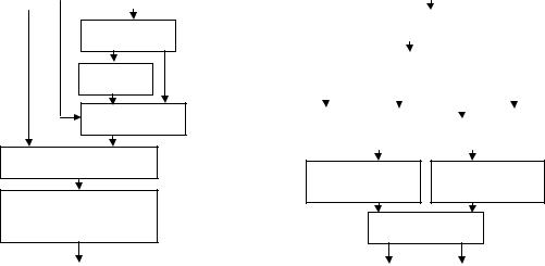
Fig.21 (a) is a diagram of the FP adder, and (b) is a diagram of the butterfly with the function of two FP adders. From the figure, we can see that a butterfly is similar to one FP adder in structure except one extra integer adder and some selection logic. Table 10 shows that such butterfly structure saves 37% area compared with two simple adders.
This reduction is due to the property of FP addition. For a fixed-point butterfly, no operations can be shared.
Structure |
Area (um2) |
Delay(ns) |
|
|
|
Two FP adders |
10412 |
7.49 |
|
|
|
Butterfly |
6545 |
8.14 |
|
|
|
Table 10. Comparison of two FP adders and a ‘butterfly’
6.2 Results comparison
We implement the IDCT in 32-bit IEEE FP, 15-bit radix-16 lightweight FP and fixed-point algorithms (see the comparison in Table 11). In the fixed-point implementation, we preserve 12-bit accuracy for constants, and the widest bit-width is 24 in the whole algorithm (not fine tuned). From the perspective of power, the lightweight FP IDCT consumes only around 1/10 power compared to the IEEE FP IDCT, and is comparable with the fixed-point implementation.
fa |
sign |
fb |
|
|
|
|
|
|
Alignment
negation |
Mux
Fraction Addition
Leading-one detection & normalization
|
|
fa+fb |
|
|
|
|
Fig. 21 |
(a) FP adder |
|
||
|
|
|
|
|
|
Implementation |
Area(um2) |
|
Delay(ns) |
Power(mw) |
|
|
|
|
|
|
|
IEEE FP |
926810 |
|
|
111 |
1360 |
|
|
|
|
|
|
Lightweight FP |
216236 |
|
|
46.75 |
143 |
|
|
|
|
|
|
Fixed-point |
106598 |
|
|
36.11 |
110 |
|
|
|
|
|
|
Table 11. Comparison of three implementations of IDCT
7. Conclusion
In this paper, we introduce C++ and Verilog libraries of lightweight FP arithmetic, focusing on the most critical arithmetic operators (addition, multiplication), and the most common parameterizations useful for multimedia tasks (bitwidth, rounding modes, exception handling, radix). With these libraries, we can easily translate a standard FP program to a lightweight FP program, and explore the system numerical performance vs. hardware complexity tradeoff.
An H.263 video codec is chosen to be our benchmark. Such media applications do not need a wide dynamic range and high precision in computations, so the lightweight FP can be applied efficiently. By examining the histogram information of FP numbers and relationship between PSNR and bit-width, we demonstrate that our video codec have almost no quality degradation when more than half of the bit-width in standard FP is reduced. Other features specified in the standard FP, such as rounding modes, exception handling and the radix choice, are also discussed for this particular application. Such optimization offers huge reduction in hardware cost. In the hardware implementation of IDCT, we combined two FP adders in a butterfly (basic component of IDCT), which further reduced the
fa |
|
|
|
|
|
fb |
|
|
|
|
|||
|
|
|
|
|
|
|
|
|
|
|
|
|
|
|
|
|
|
|
|
|
|
|
|
|
|||
|
|
|
|
|
Alignment |
|
|
||||||
|
|
|
|
|
|
|
|
|
|
|
|||
|
|
|
|
|
|
|
|
||||||
|
|
|
|
|
|
|
|
||||||
|
|
|
negation |
|
|
|
|
|
|||||
|
|
|
|
|
|
|
|
|
|
|
|
|
|
|
|
|
|
|
|
|
|
|
|
|
|
|
|
|
|
|
|
|
|
|
|
|
|
|
|
|
|
|
Fraction |
|
|
|
|
|
|
|
Fraction |
||||
|
Addition |
|
|
|
|
|
|
|
Addition |
||||
|
|
|
|
|
|
|
|
|
|
|
|
|
|
Normalization Leading-one
detection
Selection logic
fa+fb fa-fb
Fig. 21 (b) FP butterfly
hardware cost. At last, we show that power consumption of the lightweight FP IDCT is only 10.5% of the standard FP IDCT, and comparable to the fixed-point IDCT.
Reference
[1]D. Dobberpuhl, “The design of a high performance low power microprocessor,” International Symposium on Low Power Electronics and Design, Aug 1996, pp11-16
[2]S. Kim, W. Sung, “Fixed-point error analysis and word length optimization of 8X8 IDCT architectures,” IEEE Trans. Circuits Syst. Video Technol. vol. 8, Dec. 1998, pp 935-940
[3]K. Kum, J. Kang, W. Sung, “AUTOSCALER for C: An optimizing floating-point to integer C program converter for fixed-point digital signal processors,” IEEE Trans. Circuits. Syst., vol. 47, Sep.2000, pp 840-848
[4]“IEEE-standard for Binary Floating-Point Arithmetic”, ANSI/IEEE Std 754-1985, The Institute of Electrical and Electronics Engineers, Inc, Aug 1985
[5]D.M. Samanj, J. Ellinger, E.J. Powers, E.E. Swartzlander, “Simulation of variable precision IEEE floating point using C++ and its application in digital signal processor design,” Circuits and Systems, Proceedings of the 36th Midwest Symposium on,
1993, |
pp.1509-1514, |
[6]R. Ignatowski, E.E. Swartzlander, “Creating new algorithm and modifying old algorithms to use the variable precision floating point simulator,” Signals, Systems and Computers, 1994 Conference Record of the Twenty-Eighth Asilomar Conference on , vol. 1 , 1994, pp152-156
[7]X. Wan, Y. Wang, W H. Chen, “Dynamic range analysis for the implementation of fast transform,” IEEE Trans. Circuits. Syst. for Video Technology, vol. 5, Apr. 1995, pp.178-180
[8]Y.F. Tong, D. Nagle, R.A. Rutenbar, “Reducing power by optimizing the necessary precision/range of floating-point arithmetic,” IEEE Trans. VLSI Systems, vol.8, Jun. 2000, pp. 273 –286
[9]“A Proposed Standard for Binary Floating-Point Arithmetic, Draft 8.0 of IEEE Task P754”, The Institute of Electrical and Electronics Engineers, Inc, 1981
[10]S.F. Anderson et al., “The IBM system 390 model 91: Floating point execution unit,” IBM J. Res. Dev., vol 11, pp3453,1967
[11]“IEEE-standard specifications for the implementations of 8X8 inverse discrete cosine transform,” IEEE Std 1180-1990, Institute of Electrical and Electronics Engineers, Inc, 1990
[12]E. Hokenek, R.K. Montoye, “Leading-zero anticipator (LZA) in the IBM RISC System/6000 floating-point execution unit,” IBM J.Res. Develop. Vol. 34, Jan. 1990, pp.71-76
[13]S.F. Oberman, H.AL-Twaijry, M.J. Flynn, “The SNAP project: design of floating point arithmetic units,” Proc. 13th IEEE Symp. on Comp. Arith., 1997, pp 156-165
[14]K.P. Acken, M.J. Irwin, R. M. Owens, “Power comparisons for barrel shifters,” Int. Symp. Electronics and Design, 1996, pp 209-212
[15]R.K. Montoye, E. Hokenek, S.L. Runyon, “Design of the IBM RISC System/6000 floating-point execution unit,” IBM J.Res. Develop. Vol. 34, Jan. 1990, pp.59-70
[16]R.V.K. Pillai, D. Al-Khalili, A.J. Al-Khalili, “A low power approach to floating point adder design,” Proc. IEEE Int. Conf. on Comp. Design: VLSI in Computers and Processors, 1997, pp. 178 -185
[17]J.M. Rabaey, “Digital integrated circuits: A design perspective,” Prentice Hall Electronics and VLSI Series, pp 414417
[18]A. Artieri, O. Colavin, “A chip set core for image compression,” IEEE Trans. on Consumer Electronics, vol. 36, Aug. 1990, pp.395 –402
[19]P.C.H Meier, R.A. Rutenbar, L.R. Carley, “Exploring multiplier architecture and layout for low power,” in Custom Integrated Circuits Conf., 1996
[20]A.W. Burks, H.H. Goldstine, J. von Neumann, “Preliminary discussion of the logical design of an electronics computing instrument,” Computer Structures: Reading and Examples, McGraw-Hill Inc., 1971