

Architectural Structures
.pdfLabor Palace Turin (1961)
Architect/Engineer: Pierre Luigi Nervi
This project, first price of a design competition, was build for the centenary of Italy’s unification in 1981 to house an international labor exhibition. The classic order of this structure is a departure from Nervi’s funicular oeuvre. Due to a short time from design to completion, one of the design objectives was fast construction. The solution of 16 freestanding mushroom structures allowed for sequential manufacture and erection, a
critical factor for speedy completion. The facility measures 158x158m and has a height of 23m. Each of the 16 units measures 38x38m. The mushrooms are separated by
gabled skylights of 2m width, that help to accentuate individual units visually, provide natural lighting and structural separation. Each mushroom consists of concrete pylons
that taper from 2.4m at the top to 5.5m at the base in response to the increasing bending moment toward the base. The pylons are rounded at the top and cross-formed at the base. Twenty tapered steel plate girders cantilever from the pylons in a radial patterns; with increasing depth toward the support in response to greater bending. Triangular brackets strengthen the transition from girder to pylon. Stiffener plates welded to girder webs stabilizes them against buckling and provide a visual pattern in response to the structural imperatives.
11-9 HORIZONTAL SYSTEMS Bending Resistant
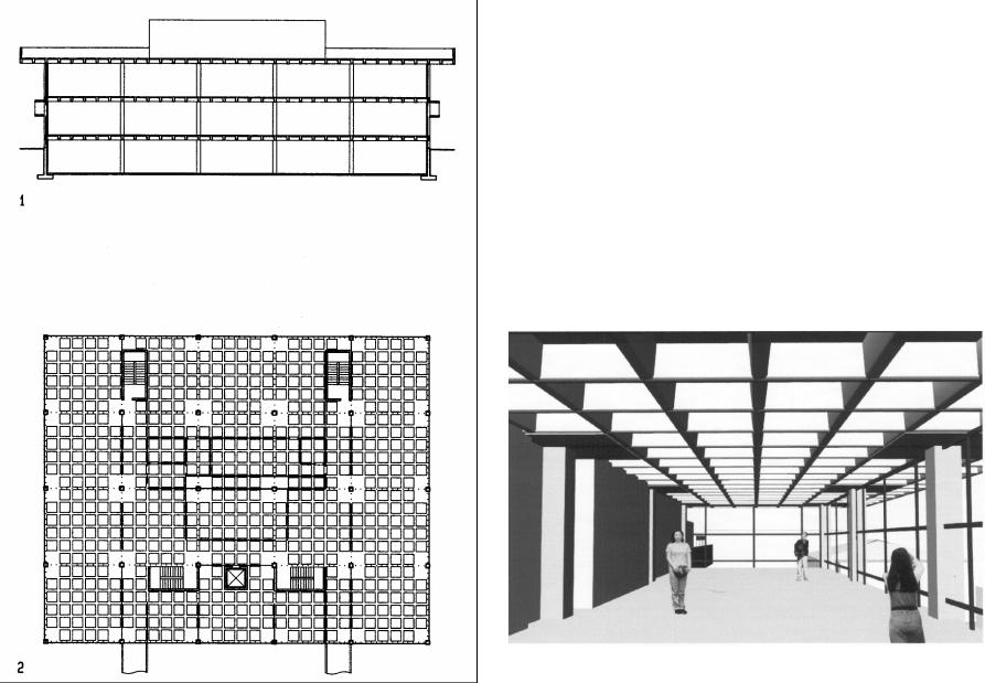
Watt Hall, University of Southern California, Los Angeles (1974)
Architect: Sam Hurst
Watt Hall, the USC School of Architecture building, features 5 x 5 foot concrete waffle slabs, supported by a column grid of 30 x 30 feet (9x9 m). Four panels above each column are solid to resist shear the stress which is maximum over the columns. The exposed waffle slab provides a rich ceiling pattern as well as an educational demonstration of a common construction technology.
11-10 HORIZONTAL SYSTEMS Bending Resistant

Vierendeel
Named after the Belgian builder Vierendeel who is credited with its invention, the Vierendeel girder has rectangular panels, composed of struts, which are connected by moment resistant joints. Since load is resisted in frame action rather than truss action, the terms Vierendeel girder or frame (depending on configuration) are more suitable than Vierendeel truss which implies triangular panels and axial stress rather than bending stress. Compared to trusses with triangular panels, rectangular Vierendeel panels allow ducts or pipes to pass through with greater ease. Rectangular panels also have a different visual appearance. Vierendeel girders resist load in combined axial and bending stress and, thus, tend to be less efficient than trusses of triangular panels, which resist load in axial tension and compression. Bending stress in members varies from zero at the neutral axis to maximum at the outer fibers, but axial stress is uniform and thus more efficient. For convenience, we refer to horizontal and vertical struts as chord and web, respectively. The load bearing of Vierendeel girders and frames can be visualized by magnifying their deformation under load. A single-bay Vierendeel1 deforms under gravity load similar to a moment resisting portal frame2: top and bottom chords develop positive moments at mid span and negative moments at both ends, with two inflection points at the transition. Chord rotation is transmitted to webs and deforms them into S-shapes. The resulting web moments are inverse on top and bottom, with inflection points of zero moment at mid height. Under lateral load3 both chord and web struts are deformed with single inflection points in the middle. In multi-bay girders5, too, webs deform under both gravityand lateral loads similar to frames6-7, with inflection points that may be hinged. However, the chords develop single inflection points for both lateral and gravity loads, except the center bay which has two inflection points under gravity load. In girders with even number of bays and a center web strut, all chords have single inflection points. Since all web struts, assume inflection points under both gravity and lateral load, they could have hinges at those points, provided those hinges can resist out-of-plane deformation to avoid instability.
1Single-bay Vierendeel girder
2Deformation under gravity load
3Deformation under lateral load
4Web struts with hinges at inflection points
53i-bay Vierendeel girder
6Deformation under gravity load
7Deformation under lateral load
83-bay web struts with hinges at inflection points
11-11 HORIZONTAL SYSTEMS Bending Resistant
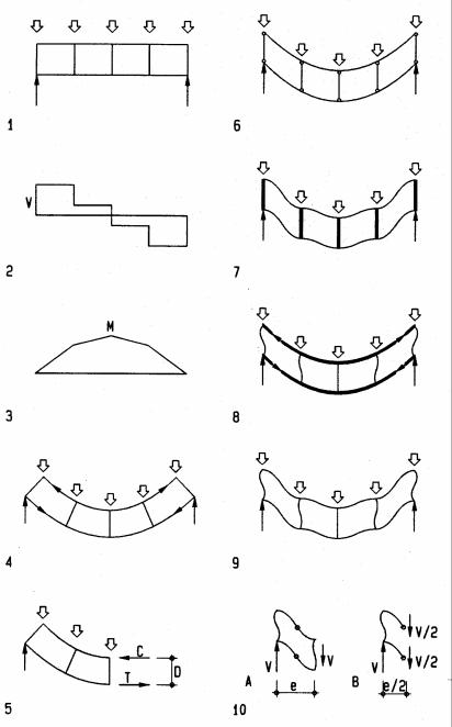
Vierendeel girders resist load in combed beam action and frame action as shown on the left and right diagrams, respectively. Load causes global shear and bending which elongates the bottom in tension and shortens the top in compression. The internal reaction to global shear and bending is different in a Vierendeel compared to a beam. A beam's bending stress varies gradually over the cross-section, but global bending in a Vierendeel causes concentrated tension and compression forces in the chords. By visual inspection we can derive simple formulas for approximate axial and shear forces and bending moments. Respective stresses are found using formulas for axial, shear and bending stress and superimposing them. Chord tension T and compression C are computed, dividing the respective global moment M by frame depth D (distance between centers of chords).
C = T = M / D
Bending of individual struts can be visualized too. In a structure where moment resistant strut/chord connections are replaced with hinges, chords would deflect as independent beams6. Assuming flexible chords and stiff webs, vertical shear would deform chords to S-shapes with inflection point. Assuming flexible webs and stiff chords, horizontal shear, caused by a compressive force pushing outward on top and a tensile force pulling inward on the bottom, would deform webs to S-shapes with inflection point. The combined effect of these two idealized cases imparts S-shaped deformation and inflection points in both chord and web struts. The deformation yields strut bending moments which vary from positive to negative along each strut. Top and bottom chords carry each about half the total shear V. Assuming inflection points at midpoints of chords, the local chord moment M is half the shear V multiplied by half the chord length.
M = (V / 2) (e / 2)
The moment M is maximum at supports where shear is greatest and equal to support reactions. For equilibrium, webs have to balance chord moments at each joint. Their moment equals the difference of adjacent chord moments.
1Gravity load on a Vierendeel
2Global shear (in overall system rather than individual members)
3Global bending (in overall system rather than individual members)
4Compression and tension in top and bottom chord, respectively
5Free-body visualizes derivation of chord tension T and compression C
6Global shear deformation
7Chord bending, assuming flexible chords and stiff webs
8Web bending, assuming flexible webs and stiff chords
9Combined chord and web bending under actual condition
10Free-bodies visualize derivation of chord bending moment M
11-12 HORIZONTAL SYSTEMS Bending Resistant
Configurations
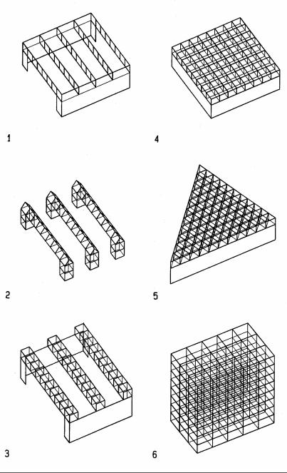
Vierendeels may have various configurations, including one-way and two-way spans.
One-way girders may be simply supported or continuous over more than two supports. They may be planar or prismatic with triangular or square profile for improved lateral load resistance. Some highway pedestrian bridges are of the latter type. A triangular crosssection has added stability, inherent in triangular geometry. It could be integrated with bands of skylights on top of girders.
When supports are provided on all sides, Vierendeel frames of two-way or three-way spans are possible options. They require less depth, can carry more load, have less deflection, and resist lateral load as well as gravity load. The two-way option is well suited for orthogonal plans; the three-way option adapts better to plans based on triangles, hexagons, or free-form variations thereof.
Moment resistant space frames for multi-story or high-rise buildings may be considered a special case of the Vierendeel concept.
1One-way planar Vierendeel girder
2One-way prismatic Vierendeel girder of triangular cross-section
3One-way prismatic Vierendeel girder of square cross-section
4Two-way Vierendeel space frame
5Three-way Vierendeel space frame
6Multi-story Vierendeel space frame
11-13 HORIZONTAL SYSTEMS Bending Resistant

Salk Institute, La Jolla, California (1966)
Architect: Louis I. Kahn
Engineer: August Komendant and Fred Dubin Associates
The Salk Institute in Lajolla houses two research laboratories, flanked by service towers facing the outside, and study cells for scientists facing a central courtyard with view to the Pacific Ocean. North being oriented to the left on the drawing, offices are located on both west ends of the two lab wings. Mechanical rooms are located to the east. The courtyard concept was inspired by Dr. Salk's memory of the monastery of St. Francis of Assisi which he visited in the 1950's. This concept and the sparse use of material, reinforced concrete, accented by the study cell's teak wood finish, give the Salk Institute a serene beauty.
To avoid interior columns for greater flexibility, 9 ft (2.7m)-deep Vierendeel girders of prestressed concrete span across the width of the labs. These girders are located at interstitial spaces between ceiling and floor to provide space for ducts and pipes, allowing access to change them as required by evolving research needs. The Vierendeel struts vary in thickness and shape to reflect variable stress patterns. Topand bottom chords are tapered for increased depth toward the supports where global shear, which generates chord bending stress, is greatest. Vertical struts, too, vary from minimum thickness at mid-span to maximum toward the supports, since their bending is the sum of the bending of all chords connected to them. However, the greatest bending in vertical struts occurs not over the supports but at struts next to them, since they absorb bending from chords on both sides; yet end struts transfer bending to only one set of chords.
Perspective section, courtesy Salk Institute
11-14 HORIZONTAL SYSTEMS Bending Resistant
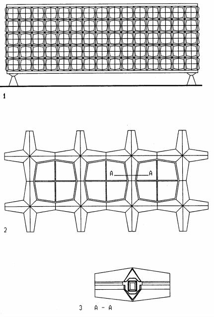
Beinecke library, Yale University, New Haven, Connecticut (1963)
Architect and Engineer: Skidmore, Owings and Merrill
The Beinecke library of Yale University for rare books has a 5-level central book tower, freestanding within a single story donut-shaped hall that extends over the full height of the tower. The tower holds 180,000 books and is climatically separated from the surrounding hall by a glass curtain wall.
The library’s five-story open space is framed by a unique structural concept. Four Vierendeel steel frames, 50 ft (15 m) high, support the roof and wall load and span 131 and 88 ft (40 and 27m) in length and width, respectively. The frames are supported by a reinforced concrete plate that transfers the load via steel pin joints to four reinforced concrete pylons. The Vierendeel frames consist of 8'-8" (2.6m) prefabricated steel crosses, welded together during erection. The cladding of the crosses express pin joints at mid-points of chord and web struts, where inflection points of zero bending occur. The pin joints express two-way hinges by the tapering. This does not represent actual construction of the steel frame behind the cladding. If the frame had in fact two-way hinges, out-of-plane instability would result. This is a visual weakness of an otherwise compelling tectonic expression.
11-15 HORIZONTAL SYSTEMS Bending Resistant
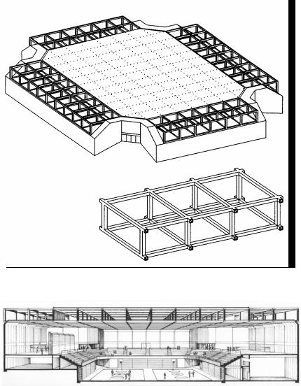
Recreation center, UC Davis, California
Architect: Perkins & Will Engineer: Leon A. Riesemberg
The recreation center for the University of California at Davis holds 10,000 spectators for occasional events. Considering the low-rise context around the facility, a major design objective was to minimize the height. This was achieved by several means. The main level is 10 ft (2.7m) below grade. Landscaped earth berms, filled from the excavated soil, surround the facility to reduce its visual height. Along the building edge the roof deck is attached to the bottom chord to further reduce the bulk of the facility. The exposed space frame articulates the facade as well.
The Vierendeel space frame of steel tubing spans 252x315 ft (77x96m) with modules of 21x21x14ft (6x6x4m) for span/depth ratios of 18 and 22 in width and length directions, respectively. The optimum depth determined by computer was 15ft, but 14ft, the limit for rail or highway transportation was selected. The structure consists of 16in (406 mm) square tubing, ranging from 3/16 to 5/8in (5 to 16mm) thickness according to force distribution. Compared to a space truss with diagonal struts, Vierendeel frames make it easier to integrate lighting, mechanical ducts, and catwalks for maintenance. The structure weighs 15psf (73kg/m2) and was built in 1977 for $11.54/ft2 ($124/m2). It was assembled in units spanning 1/3 the width of 252ft (77m). For economy sake, the tubular struts where shop welded from steel plates rather than using finished tubing.
11-16 HORIZONTAL SYSTEMS Bending Resistant
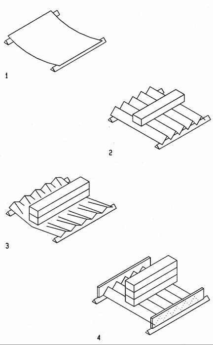
Folded Plate
The effect of folding on folded plates can be visualized with a sheet of paper. A flat paper deforms even under its own weight. Folding the paper adds strength and stiffness; yet under heavy load the folds may buckle. To secure the folds at both ends increases stability against buckling
1Flat paper deforms under its own weight
2Folding paper increases strength and stiffness
3Paper buckling under heavy load
4Secured ends help resist buckling
11-17 HORIZONTAL SYSTEMS Bending Resistant
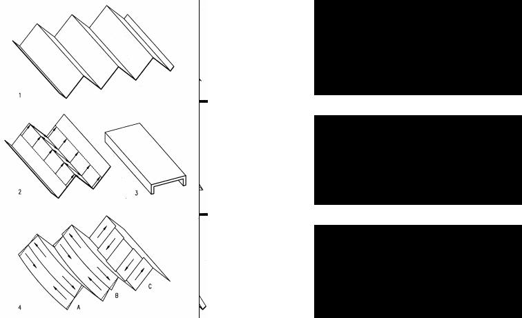
Folded plate behavior
Folded plates combine slab action with beam action. In length direction they act like thin inclined beams of great depth, stabilized against buckling at top and bottom by adjoining plates. In width direction they are one-way slabs that span between adjacent plates.
1Folded plate concept
2Slab action in width direction
3Slab-and-beam equivalent
4Beam action in length direction
ABending deformation causes top compression and bottom tension
BHorizontal shear caused by compression and tension
CVertical shear is maximum at supports and zero at mid span
Bending in folded plates causes top compression and bottom tension. Folded plates also tend to flatten out under gravity load, which may be prevented by walls or frames at end supports. Tendency of end panel buckling can be resisted by edge beams.
1Bending visualized as external compression and tension forces
2Flattened folded plate under gravity load
3Folded plate with walls and frames to resist flattening
4Buckled end panels
5End panels stabilized by edge beams
AStabilizing wall at support and, for long systems, at mid-span
BStabilizing frame at support and, for long systems, at mid-span
CEdge beam to stabilize end panel against buckling
11-18 HORIZONTAL SYSTEMS Bending Resistant