

anatomya / 69618356
.pdfArch Orthop Trauma Surg (2002) 122 : 262–268
DOI 10.1007/s00402-001-0361-8
O R I G I N A L A RT I C L E
F. Adam · D. S. Hammer · D. Pape · D. Kohn
Femoral anatomy, computed tomography and computer-aided design of prosthetic implants
Received: 3 June 2001 / Published online: 12 January 2002
© Springer-Verlag 2002
Abstract Precise digital data of the internal femoral anatomy are necessary to develop new prosthetic implants with computer-aided design (CAD) techniques. Thirty human cadaveric femurs of central European origin were analysed by high precision computed tomography (CT) using thin slice and high resolution imaging. The CT data were image processed with thresholding to obtain a reconstruction of the cortical bone geometry. The CT threshold for cortical bone was optimized by comparison with saw cuts of macerated femurs. For each specimen a three-di- mensional (3D) model of the cortical femur was calculated by the CAD system based on the processed CT data. Virtual 3D models of the 30 femurs were used to adjust a hypothetical stem to the proximal femur anatomy by repeated virtual implantations. The CAD system allowed for evaluation of anatomical parameters after hip reconstruction, amount of bone removal, and cortical bone contact. The fit and fill of the stem could be tested before clinical application and implant-related problems could be corrected.
Keywords Femur · Anatomy · Computed tomography · Computer-aided-design · Prosthetic implants
Introduction
Hip arthroplasty is one of the most beneficial procedures in orthopaedic surgery. Aseptic loosening of the femoral component in the long-term follow-up of cemented hip arthroplasty is one of the main complications. This led to
F. Adam ( ) · D.S. Hammer · D. Pape · D. Kohn Department for Orthopaedic Surgery, University of Saarland, 66424 Homburg/Saar, Germany
e-mail: Frank.Adam@med-rz.uni-sb.de,
Tel.: +49-6841-1624500, Fax: +49-6841-1624534
F. Adam
Universitätskliniken des Saarlandes, Orthopädische Klinik und Poliklinik, 66421 Homburg/Saar, Germany
the development of implants with bony ingrowth to the prosthetic surface. Cementless femoral components with biological fixation are used more and more often to avoid the disadvantages of bone cement and because of the ease of implantation.
Cementless femoral components need exact contact to the supporting cortical bone and optimal fit and fill of the proximal femur to reduce micromotion and obtain primary stability for bony ingrowth and long-term stability [24, 27]. Noble et al. demonstrated that the femoral cavity has no uniform shape and described the great variability of femoral endosteal anatomy [17]. Because of this variability, most cementless stems are so-called ‘straight stems’ [27]. These stems disregard the different anatomy between left and right femurs. Additionally, a straight stem design limits the fit and fill that can be achieved at implantation. An ideal cementless stem should transfer the loads to the bone on an area large enough to minimize local stress and stem-bone motion [24]. A long-term concern is the bone remodelling that can occur because of altered stresses and strains in the bone. Reactive bone remodelling may lead to thigh pain and bone resorption [14]. An anatomically shaped femoral component with an ideal fit and a maximum of cortical bone contact could minimize local stress on the bone.
Some groups used three-dimensional (3D) anatomical reconstructions as the basis for femoral component design [19, 25]. Studies using computed tomography (CT) combined with image processing methods revealed the higher accuracy of CT compared with conventional radiographs [6, 9, 21, 22]. Furthermore, systems for individual component design, so-called custom-made stems, have been published [1, 3, 5]. In these studies the anatomical data were based on CT examinations with 2–5 mm slice thickness and up to 10 mm slice spacing. Problems of dividing cortical from cancellous bone in the proximal part of the femur and low resolution in the longitudinal direction resulted from these thick slices. Modern CT scanners, high resolution imaging techniques and fast image processing computers allowed for exact 3D bone reconstructions (Fig. 1) [12].
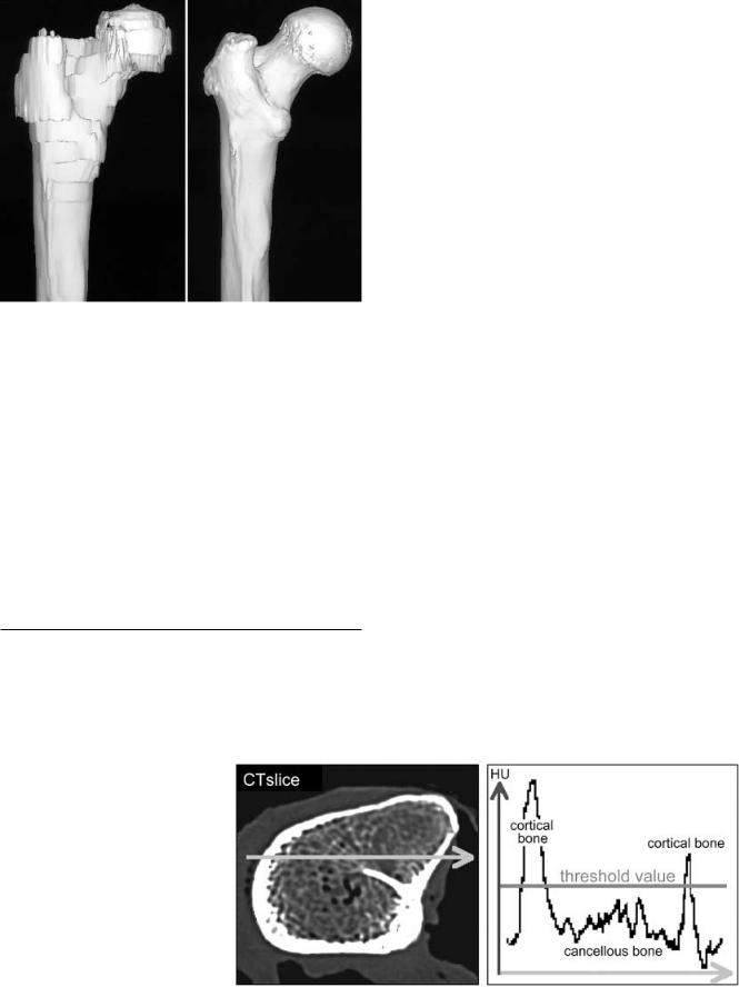
Fig. 1 Three-dimensional (3D) surface reconstruction of the proximal femur based on 5 mm computed tomography (CT) slices and spacing (left side) and high resolution, thin slice CT (right side)
Precise data of the internal femoral anatomy are necessary to develop anatomically shaped prosthetic implants using computer-aided design (CAD) and computer-aided manufacturing (CAM) techniques. The objective of this study was to evaluate precise anatomical data of the femur by using high resolution CT imaging and femur specimens to built a digital database of the human femoral anatomy. The anatomical data should be transferred to a CAD system to calculate highly accurate, virtual 3D models of the femurs. Based on modern CAD techniques, we wanted to develop an anatomically shaped femoral prosthetic component with a maximum of cortical bone contact and optimal fit and fill of the proximal femur.
Materials and methods
Anatomical database
For the examination 30 cadaveric femurs of central European origin were used. The mean age was 66.8 years (range 45–88 years) at the time of death. Thus, the specimens could be considered to
Fig. 2 Selection of cortical bone by thresholding. Profile of HU values along a crosssectional CT slice. The high peaks are in regions of high density cortical bone. The optimal threshold for cortical bone is slightly above the HU values for cancellous bone
263
be representative of potential candidates for hip arthroplasty. Twenty-two bones were taken from men and 8 from women. The mean height of the deceased was 168 cm (range 155–188 cm), and the mean weight was 73.5 kg (range 53–120 kg). The women were shorter (mean 162 cm) and weighed less (68 kg) than the men (170 cm, 75 kg). The size of the femur specimens used was deliberately chosen to be a wide range.
CT examination
First, all femurs were examined by conventional radiographs according to Noble et al. [17] to evaluate the length of the femur, the antecurvation, the neck-shaft angle, the femoral head offset and the anteversion of the neck. In a second step, each individual femur was imaged by CT (Somatom plus S, Siemens AG, Erlangen, Germany) with a high resolution technique using the 512× 512 pixel matrix. Scan parameters were 1 mm slice thickness and spacing from the top of the femoral head down to the lesser trochanter. Below the lesser trochanter 5 mm slices with 3 mm spacing were used. Images were taken down to the diaphyseal isthmus. For image reconstruction a high resolution kernel was utilized to obtain precise data even from small cancellous bone structures. Depending on the length of the bone, about 140 slices resulted for each femur using these scan parameters. The image data were stored on an optical disc and transferred to a personal computer (PC) system for further evaluation.
To determine the size of the endosteal cavity, a special medical imaging software (MIMICS, Materialise, Belgium) was used. The cortical bone was extracted from cancellous bone by density thresholding. The underlying principle of density thresholding is the removal of all image pixels with lower density than the defined threshold from the CT scan by image processing. Therefore, a profile of CT gray values (Hounsfield units, HU) was defined along the cross-section of the CT slice. The resulting profile showed high peaks in regions of high density cortical bone. Because of noise, beam hardening and the partial volume effect, the HU values for cortical bone were dispersed, resulting in curved peaks for the cortex in the HU profile (Fig. 2). We measured up to 0.5 mm difference in cortical thickness by choosing higher or lower thresholds for the cortical bone. This also led to different diameters of the femoral cavity.
Validation of density thresholding
A validation was performed to find and optimize the threshold for cortical bone. Anatomical saw slices of the specimens were used as a reference. Three femurs were macerated to remove all soft tissue, blood and fat from the outside and inside. A special saw guide was developed that could also be used as a holding device for the CT scanner. The femurs were fixed in the device and examined by CT with 5 mm slice thickness and 5 mm intervals beginning at the top of the femoral head. In order to compare the saw slices with the
264
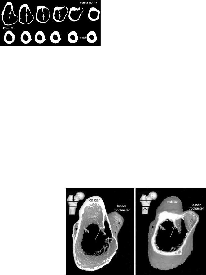
Fig. 3 Selection of cortical bone by image thresholding (threshold 650 HU). Computed CT slices of femur specimen no. 17. Calcar femorale orientated at the top. The femoral ‘thigh spur’ (arrows) divided the femoral canal partially from the cancellous bone of the lesser trochanter
computed slices, the bones were marked before cutting to obtain the right orientation of the slices. Afterwards, the femur specimens were exactly cut to correspond to the CT slices using the saw guide. Each single slice was labelled and photodocumented for comparison with the computed slices. The dimension of cortical bone processed by the imaging software was compared with the corresponding saw cut using a graph millimeter scale. It was found that a constant threshold for all bones cannot be used because the density of cortical bone depends on patient properties and imaging parameters. The best conformity of saw cuts and computed cortical bone was seen by using a threshold slightly above the HU values of cancellous bone in the mid-third of the cortical peak, usually between 600 and 800 HU. This thresholding yields a close cortical bone structure, especially in the proximal part of the femur with areas of thin cortex.
Femur computer model
The CT data were subsequently processed by the image software to obtain a reconstruction of the cortical bone geometry of each slice (Fig. 3). In all computed slices a relative thick internal septum made of cortical bone remained in the femoral canal in the lesser trochanteric area (Fig. 4). This ‘femoral thigh spur’ was first described and named by the anatomist Merkel in 1874 [15]. Adam et al. published a detailed description of the internal calcar septum recently [2]. All image-processed CT data were transferred to a CAD
Fig. 4 Three dimensional reconstruction of cortical bone in the lesser trochanteric area. Arrows indicate the internal calcar septum. Left: view from cranial in the femoral cavity. Right: view from distal
system, and a geometrical 3D model of cortical bone was calculated for each femur.
Virtual prosthetic implantation
To develop an anatomically shaped prosthetic stem, virtual implantations were performed in the generated femur models.
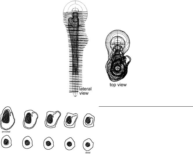
The protocol for the virtual prosthetic implantation was (Fig. 5):
•determine the femoral head centre and the longitudinal axis of the femoral canal
•adjust femoral head resection line
•determine from top view one circle in the femoral diaphysis that could be drawn inside with endosteal cortical contact
•place the prototype stem in line with the longitudinal axis above the circle
•adjust depth of implantation and anteversion using frontal and lateral views
• |
check fit and fill of the implant on cross-sectional slices (Fig. 6) |
• |
adjust stem size in true scale steps |
Factors to assess the fit of the designed implant shape were:
•reconstruction of the femoral head centre and femoral offset
•no varus or valgus malposition in the frontal view
•no removal of cortical bone in the proximal part of the femur
•slight removal of bone with a maximum of 1.0 mm in the cylindrical diaphyseal part
•close cortical bone contact medial at the calcar and lateral at the lesser trochanteric region
•good cortical contact proximal at the anterior part and in the diaphysis
•protection of the internal calcar septum for posteromedial implant support
•conical proximal implant shape on frontal and lateral views to obtain press-fit fixation
•corresponding shape of bone bed and prosthetic implant without additional removal of bone during insertion of the stem
Virtual implantations of the prototype stem were performed with all digitized femur specimens of the CT study. In many virtual stem implantations in anatomically different femurs, the shape of the stem could be improved according to the implantation protocol. A final assessment of the stem shape was performed by generating 3D surface reconstructions of the femur model and the inserted prototype stem. The 3D reconstructions were cut by image processing frontally and laterally to evaluate the final fit and fill of the implant. With special CAD software features, close cortical bone
265
Fig. 5 Virtual prosthetic implantation of a prototype stem in a contour femur model. Implant aligned with femoral longitudinal axis. Determination of resection level. Evaluation of femoral head centre according to anatomy
Fig. 6 Evaluation of implant fit and fill on cross-sectional slices. Calcar femorale orientated at the top. Close cortical bone contact medially, laterally and in the diaphysis. Support of the anatomically shaped stem in the wide dorsomedial femoral cavity by the thigh spur
contact of the implant was checked to estimate primary stability (Fig. 7).
Final cadaver tests
For final testings of the evaluated stem shape, cadaver surgery was performed on 10 specimens. Cadaveric femurs from the CT study were used for the trials, and prototype stems were produced by CAM. The stems were made of aluminum and plastic with 1 mm increments in size. Adequate size of the fitting prototype stem was evaluated in the computer model. The femur was prepared by rigid cylindrical reamers in the distal part and broaches matching the shape of the prostheses in the proximal part. After insertion, the prototype stem was fixed in the bone bed by hammer blows. Rotational stability was measured by using a torque wrench. The torque force was increased till a movement between stem and bone could be noticed visually. Finally, the fit and the fill of the stem was evaluated by conventional radiographs in frontal and lateral views. In 5 cases the fit of the implant was additionally tested after surgery by CT using plastic prototype stems.
Results
Anatomical and CT study
As expected, the femurs ranged widely in size and shape. Femur length ranged from 378 mm to 580 mm (average 447 mm). The mean femoral head diameter was 49 mm (range 42–61 mm). Femoral head offset was measured between 39 mm and 60 mm and averaged 49 mm. Using the classification of Noble et al. [17], we found three stovepipe and two champagne-flute shaped femurs in the radiographic evaluation of the canal flare index. The others were classificated as normally shaped. The neck-shaft angle ranged from 111° to 140° and averaged 123°. The mean anteversion of the femoral neck and head according to a tangent to the femoral condyles was 26.5° (range 19°–31°). Antecurvation of the examined femurs ranged from 6° to 15° (average 9.6°).
The femoral thigh spur, a cortical-like septum or ridge in the femoral cavity, was found in all femurs on the crosssectional slices of the metaphyseal region. On CT and saw slices, the thigh spur was connected in all parts with the surrounding cancellous bone. Because of its high density and thickness, it was not removed from the CT images by the thresholding. After image processing, the thigh spur was the only bone structure left in the femoral cavity. The uppermost part of the spur always started posteromedial at the femoral calcar, reaching down to the distal part of the lesser trochanter. The length of the spur reached up to 35 mm in the longitudinal axis. The thickest part of the septum measured 3 mm and was found in all specimens close to the cortex. The septum got thinner in the femoral cavity, ending in trabecular bone formations with connection to the opposite lateral cortex. In the proximal part the

266
Fig. 7 3D surface reconstructions of the computed femur model and the inserted, ideally shaped, semi-anatomical stem (1, 2). Anatomical implant shape medially and anteriorly, straight stem design laterally, posteriorly and distally. Evaluation of close cortical bone contact. Black areas are representative for cancellous bone. Close cortical bone contact in the transparent areas (3)
thigh spur was orientated parallel to the longitudinal axis of the femoral neck. The shorter distal part was aligned to the posterior cortex. The thigh spur constantly formed an internal cortical septum between the femoral canal and the lesser trochanter, thus narrowing the proximal femoral cavity. It contributed to stabilization of the prosthetic implant dorsomedially in the wide cavity of the lesser trochanter area (Fig. 6).
Virtual stem implantation
The virtual stem implantations revealed that an anatomically shaped stem that mimics femoral antecurvation can only be inserted if it is short in the diaphyseal part or distally thinner than the width of the femoral canal. Stems shaped like this showed insufficient cortical bone contact distally, resulting in poor axial stability. The ideal implant shape providing a maximum of cortical bone contact by a corresponding shape of bone bed and implant, without the need to remove bone during insertion, was evaluated for a semi-anatomical design. This stem was straight laterally and dorsally and curved anatomically anteriorly and medially, with a straight cylindrical distal part. The proximal 3D conical shape led to press-fit metaphyseal fixation of the stem. Because of the straight distal and dorsal shape of the stem, the cortical internal calcar septum was not removed and could be used for stabilizing the implant posteromedially. Good cortical bone contact in the diaphysis was seen for a straight cylindrical distal shape, resulting in sufficient axial stability. The ideal stem shape according to virtual implantations is shown in Fig. 7.
Stem implantation in specimens
No implantation problems were encountered during the 10 final cadaver trials with CAM-produced instruments and prototype stems. Because of the straight distal part of the anatomical stem, straight reamers were also used to adapt the hard diaphyseal cortical bone to the stem. Afterwards, the drill hole could be used as a guide for the broaches to rasp the cancellous metaphyseal bone in line with the femoral axis. Evaluation visually and with conventional radiographs showed a bone bed exactly matching the prosthesis shape as required in the implantation protocol. In all femurs the fitting prototype stem was of the same size as the one evaluated in the preliminary virtual implantation. Comparison of virtual implantation and CT examination of the cadaver trials with the implanted plastic stem showed on average a difference of 3 mm (range 2–4 mm) in implantation depth of the stem. The difference for axial orientation (valgus/varus) was measured as 2° (range 1.5°–2.5°). No measurable difference for stem rotation was observed. The cortical bone contact of the plastic stem was similar to the bone contact determined in the computer model.
Primary rotational stability was measured with the torque wrench up to 30 Nm (minimum 15 Nm), depending on bone and implant size. In all cases torsion of the cadaveric femur was noticed before relative movement between the stem and bone was observed. Thus, primary rotational stability of the implant could be assumed [23].
Discussion
Cadaver trials are not very useful to develop new implant designs because the specimens will be destroyed during
the first implantation. The fit of the implant can only be judged once in each specimen. Therefore, a lot of specimens are needed for examination. The use of conventional radiographs is not satisfactory due to inaccuracies [11, 20, 21]. We developed a method to perform virtual surgery on computer models of human femurs for designing orthopaedic implants with optimal fit. The method is based on CAD techniques and precise CT examination. To obtain a high accuracy of the CT examination, to avoid motion artifacts and super-impositions, and to allow for thin slice imaging, we used fresh frozen human femurs to create the anatomical database. The exactness of the computer model relies on the one hand on the resolution of the cross-sectional CT slices influenced by the size of the image matrix and the reconstruction mode [8]. On the other hand, the resolution in the longitudinal axis is also very important, especially in the curved metaphyseal area. Step artifacts in the size of the image thickness result in the 3D reconstruction (Fig. 1). A second problem in curved areas of the bone is the definition of cortical bone by thresholding. In curved areas the cortical bone is not perpendicularly orientated to the CT slice, causing thinner cortical bone at the edges with lower CT values for cortical bone. This leads to problems in detecting cortical bone by thresholding, especially in the proximal femur with thin cortex [8]. In preliminary examinations this problem was also mentioned by other authors [12, 26]. Laine et al., for example, used a contour tracking with edge detection technique to define the cortical border [13]. He reported an accuracy of 1.1 mm (±0.7 mm, ±1SD) compared with manual measurements. A reduced 256× 256 image matrix and 2 mm axial slices at 5 mm intervals were used for the examination. Better precision was achieved for thin CT slices. An accuracy of 0.8 mm (±0.7 mm, ±2SD) comparing CTbased edge detection methods to anatomical examination was presented by Rubin et al. [20]. He used 1 mm slices spaced every 5 mm. Recently, a study published by Aamodt et al. [1] comparing thresholding and anatomical slices reported an average maximum contour deviation of 0.18 mm. Their CT parameters were: 512× 512 image matrix, 2 mm slice thickness spaced every 10 mm. The cited studies reported a high accuracy for detection of cortical bone on cross-sections. We used 1 mm slice thickness and high resolution image reconstruction mode to obtain sharp cancellous and cortical bone structures for exact thresholding. Thus, the precision of our femur model can be assumed to be about 0.18 mm or better on cross-sections. The accuracy of our thresholding was not evaluated in detail. However, anatomic validation was performed in 3 cases to optimize the threshold for the set-up used.
The precision along the longitudinal axis depends on the image voxel size determined by the CT slice thickness and distance. We used the thinnest slice thickness and spacing that was available for the CT scanner, resulting in a maximum resolution of 1 mm along the longitudinal axis. Nevertheless, slight differences in implant orientation and implantation depth were noted in the final cadaver trials. We presume that this was caused by the manual rasping procedure, in which parts of cancellous bone
267
were compressed against the endosteal cortex, or by removing cortical bone, resulting in a smaller or larger femoral cavity. Furthermore, the reported inaccuracy of the computer model could be another reason.
The fit of an implant is defined as the distance between the implant surface and the endosteum of the femur. The fill is determined as the percentage of endosteal space occupied by the implant. Because of the 3D shaped femoral cavity, an implant that completely fills the femur cannot be inserted [10]. In practice, there is no clear demarcation between the cancellous bone of the femoral cavity and the endosteal cortical bone. In addition, cancellous bone is more biologically active than cortical bone and necessary for bony ingrowth of the implant. It is described that the highest strength and stiffness of the cancellous bone in the proximal femur are located close to the endosteal cortex [4]. As mentioned above, a maximum of close cortical bone contact is needed to obtain primary and long-term stability of the stem [18, 23, 27]. It is obviously difficult to develop an implant shape that meets all of these requirements.
The most important aim of our implant design was to restore the anatomy and physiological metaphyseal transfer of stress to the bone. An anatomical proximal implant shape that follows the endosteal surface medially and anteriorly leads automatically to 3D metaphyseal fixation as intended [14]. Together with dorsomedial cortical support of the internal calcar septum, primary rotational stability was noted. An internal cortical structure was also mentioned in other CT studies of the proximal femur but not considered for prosthetic design. Dai et al. reported that a dense calcar trabeculation modified the femoral cavity in the trochanteric region [7]. In addition, Walker and Robertson mentioned a prominent calcar on cross-sections at the osteotomy level in many cases [25]. Laine et al. described a diversity of the femoral medullary canal by a dense trabecular ridge in nearly all femurs examined by CT [13]. We recently published a detailed description of the internal calcar septum based on specimen studies, conventional radiographs and CT examinations [2].
The shape of the bone bed should be exactly congruent to the prosthesis, with a minimum of additional bone removal while rasping the femoral cavity from the top to avoid additional bone loss. This required a straight implant shape in the distal part and a straight shape dorsally and laterally at the greater trochanter. Walker published their data about an optimally shaped press-fit stem with some parallels to our findings [25]. Their stem is totally anatomically shaped in the proximal part. The distal part of the stem is straight and cylindrical. The proximal part is slightly curved also on the lateral and dorsal aspects. Thus, this stem is not completely conical in the proximal part, which should theoretically lead to partly inadequate bone contact proximally because additional cancellous bone at the greater trochanter has to be removed while preparing the bone bed.
Nevertheless, it was seen in the realistic virtual implantations that it is impossible to develop a non-individ- ual prosthetic shape with optimal fit and fill in any femur. Because of the individual shape of the femoral cavity [5,

268
16, 17], in many cases the bone has to be adapted to the prostheses to achieve sufficient fit. This was also reported by Clarke et al. [6]. They compared the percentage of fit and fill of the proximal femur by three anatomical stems using a computerized templating model. Results showed that the overall percentage fit and fill was similar and satisfactory in most of the patients. If a satisfactory fill was not achieved with one prosthesis, a differently shaped prosthesis did not significantly improve fill.
We conclude from our study that the method presented to build up an anatomical digital database by using high resolution CT and thresholding image processing is a precise technique and that its accuracy is adequate to develop new prosthetic implants using CAD techniques. Our method allowed for realistic virtual testings in many different bones to optimize the design of a prosthetic implant and to anticipate surgical problems. The semi-anatomically shaped stem developed with this method obtained close cortical bone contact and preserved the internal calcar septum in the proximal femur, promoting initial stability and longterm optimal stress transfer to the bone. The presented method could also be suitable to develop orthopaedic implants for other parts of the skeleton.
References
1.Aamodt A, Kvistad KA, Andersen E, Lund-Larsen J, Eine J, Benum P, Husby OS (1999) Determination of Hounsfield value for CT-based design of custom femoral stems. J Bone Joint Surg Br 81: 143–147
2.Adam F, Hammer D, Pape D, Kohn D (2001) The internal calcar septum (femoral thigh spur) in computed tomography and conventional radiography. Skeletal Radiol 30: 77–83
3.Bargar WL (1989) Shape the implant to the patient. A rationale for the use of custom-fit cementless total hip implants. Clin Orthop 249: 73–78
4.Brown TD, Ferguson AB Jr (1980) Mechanical property distributions in the cancellous bone of the human proximal femur. Acta Orthop Scand 51: 429–437
5.Capello WN (1989) Fit the patient to the prosthesis. An argument against the routine use of custom hip implants. Clin Orthop 249: 56–59
6.Clarke HJ, Jinnah RH, Cox QG, Curtis MJ (1992) Computerized templating in uncemented total hip arthroplasty to assess component fit and fill. J Arthroplasty 7: 235–239
7.Dai KR, An KN, Hein Tjea (1985) Geometric and biomechanical analysis of the human femur. Orthop Trans 10: 256–261
8.Dougherty G, Newman D (1999) Measurement of thickness and density of thin structures by computed tomography: a simulation study. Med Phys 26: 1341–1348
9.Elke RP, Cheal EJ, Simmons C, Poss R (1995) Three-dimen- sional anatomy of the cancellous structures within the proximal femur from computed tomography data. J Orthop Res 13: 513– 523
10.Horne G (1992) Fit and fill: fashionable fact or fantasy? J Bone Joint Surg Br 74: 4–5
11.Iguchi H, Hua J, Walker PS (1996) Accuracy of using radiographs for custom hip stem design. J Arthroplasty 11: 312– 321
12.Laine HJ, Kontola K, Lehto MU, Pitkanen M, Jarske P, Lindholm TS (1997) Image processing for femoral endosteal anatomy detection: description and testing of a computed tomography based program. Phys Med Biol 42: 1673–1689
13.Laine HJ, Lehto MU, Moilanen T (2000) Diversity of proximal femoral medullary canal. J Arthroplasty 15: 86–92
14.Mallory TH, Head WC, Lombardi AV (1997) Tapered design for the cementless total hip arthroplasty femoral component. Clin Orthop 344: 172–178
15.Merkel FR (1874) Bemerkungen über das Os femoris. Arch Pathol Anat 59: 237–241
16.Noble PC, Alexander JW, Lindahl LJ, Yew DT, Granberry WM, Tullos HS (1988) The anatomic basis of femoral component design. Clin Orthop 235: 148–165
17.Noble PC, Box GG, Kamaric E, Fink MJ, Alexander JW, Tullos HS (1995) The effect of aging on the shape of the proximal femur. Clin Orthop 316: 31–44
18.Robertson DD (1988) Improving the fit of press-fit hip stems. Clin Orthop 228: 134–140
19.Robertson DD, Walker PS, Granholm JW, Nelson PC, Weiss PJ, Fishman EK, Magid D (1987) Design of custom hip stem prostheses using three-dimensional CT modeling. J Comput Assist Tomogr 5: 804–809
20.Rubin PJ, Leyvraz PF, Aubaniac JM, Argenson JN, Esteve P, De Roguin B (1992) The morphology of the proximal femur. A three-dimensional radiographic analysis. J Bone Joint Surg Br
74:28–32
21.Smith HW, De Smet AA, Levine E (1982) Measurement of cortical thickness in a human cadaver femur. Conventional roentgenography versus computed tomography. Clin Orthop
169:269–274
22.Sugano N, Ohzono K, Nishii T, Haraguchi K, Sakai T, Ochi T (1998) Computed-tomography-based computer preoperative planning for total hip arthroplasty. Comput Aided Surg 3: 320– 324
23.Sugiyama H, Whiteside LA, Engh CA (1992) Torsional fixation of the femoral component in total hip arthroplasty. The effect of surgical press-fit technique. Clin Orthop 275: 187–193
24.Walker PS (1987) Strains and micromotions of press-fit femoral stem prostheses. J Biomech 20: 693–702
25.Walker PS (1988) Design and fabrication of cementless hip stems. Clin Orthop 235: 25–34
26.Woolson ST, Dev P, Fellingham LL, Vassiliadis A (1986) Three-dimensional imaging of bone from computerized tomography. Clin Orthop 202: 239–248
27.Zweymüller KA, Lintner FK, Semlitsch MF (1988) Biologic fixation of a press-fit titanium hip joint endoprosthesis. Clin Orthop 235: 195–206