

Правила Кодексы / МАРПОЛ / AIR_POLLUTION_AND_ENERGY_EFFICIENCY
.pdfE
MARINE ENVIRONMENT PROTECTION |
MEPC 64/INF.22 |
COMMITTEE |
27 July 2012 |
64th session |
ENGLISH ONLY |
Agenda item 4 |
|
AIR POLLUTION AND ENERGY EFFICIENCY
First version of industry guidelines on calculation and verification of the Energy Efficiency Design Index (EEDI)
Submitted by BIMCO, CESA, IACS, ICS, INTERCARGO, INTERTANKO, ITTC, OCIMF and WSC
|
|
SUMMARY |
|
Executive summary: |
This document provides in the annex a first version of industry |
|
|
guidelines concerning the uniform implementation of the EEDI |
|
|
requirements and the role of the verifier in conducting the |
|
|
verification of EEDI |
|
Strategic direction: |
7.3 |
|
High-level action: |
7.3.2 |
|
Planned output: |
7.3.2.1 |
|
Action to be taken: |
Paragraph 5 |
|
Related documents: |
MEPC 62/5/21, MEPC 62/24; MEPC 63/INF.8, MEPC 63/23; |
|
|
resolutions MEPC.212(63), MEPC.214(63), and MEPC 64/4/32 |
|
|
|
Introduction |
|
|
1Document MEPC 62/5/21 informed the Committee of the work of a Joint Industry Working Group (JWG) on the EEDI, formed by the following international shipping associations and organizations: IACS, BIMCO, CANSI, CESA, CESS, ICS, INTERCARGO, INTERTANKO, KOSHIPA, OCIMF and SAJ. ITTC and WSC joined the JWG in 2011.
2The work of the JWG is to prepare industry guidelines providing agreed procedures
for the computation and the verification of the EEDI, compliant with the relevant IMO Guidelines in resolutions MEPC.212(63) and MEPC.214(63), to be used by the verifiers as well as the submitters when verifying and computing EEDI respectively.
3 In the 2012 Guidelines on survey and certification of the EEDI (resolution MEPC.214(63)), note 2 under paragraph 4.2.6 of the guidelines states: "A joint industry standard to support the method and role of the verifier will be developed." In order to meet this objective, the industry guidelines include a procedure for the review and the witnessing of the tank tests by the verifier.
I:\MEPC\64\INF-22.doc

MEPC 64/INF.22
Page 2
4 As discussed in document MEPC 64/4/32, the annex to this document provides the first version of industry guidelines intended to be used by the relevant parties when implementing the EEDI scheme on or after 1 January 2013.
Action requested on the Committee
5 The Committee is invited to note the first version of industry guidelines set out in the annex to this document.
***
I:\MEPC\64\INF-22.doc

MEPC 64/INF.22
Annex, page 1
ANNEX
FIRST INDUSTRY GUIDELINES FOR CALCULATION AND VERIFICATION OF
THE ENERGY EFFICIENCY DESIGN INDEX (EEDI)
|
TABLE OF CONTENTS |
|
1 |
Scope of the Guidelines ............................................................................................... |
2 |
2 |
Introduction .................................................................................................................. |
3 |
3 |
EEDI formula................................................................................................................ |
3 |
4 |
Fuel consumption and CO2 emission............................................................................ |
4 |
5 |
Capacity, power and speed .......................................................................................... |
4 |
6 |
Shaft generator and shaft motor ................................................................................... |
5 |
7 |
Weather factor fw ......................................................................................................... |
10 |
8 |
Correction factor for ship specific design elements fj ................................................... |
10 |
9 |
Capacity factor fi.......................................................................................................... |
11 |
10 |
Cubic capacity correction factor fc............................................................................... |
11 |
11 |
Innovative energy efficient technologies ...................................................................... |
11 |
12 |
Example of calculation ................................................................................................ |
11 |
13 |
Verification process ..................................................................................................... |
13 |
14 |
Documents to be submitted......................................................................................... |
13 |
15 |
Preliminary verification at the design stage ................................................................. |
15 |
16 |
Final verification at sea trial ......................................................................................... |
19 |
17 |
Verification of the EEDI in case of major conversion ................................................... |
21 |
18 |
Appendix 1: Review and witness points....................................................................... |
22 |
19 |
Appendix 2: Sample of documents to be submitted to the verifier ............................... |
24 |
20 |
Appendix 3: Verifying the calibration of model test equipment .................................... |
38 |
21 |
Appendix 4: Review and witnessing of model test procedures ................................... |
44 |
21 |
Appendix 5: Sample report "Preliminary Verification of EEDI |
52 |
I:\MEPC\64\INF-22.doc

MEPC 64/INF.22
Annex, page 2
Part I - Scope of the Industry Guidelines
1 SCOPE OF THE GUIDELINES
1.1Objective
The objective of these Industry Guidelines for calculation and verification of the Energy Efficiency Design Index (EEDI), hereafter designated as "the Industry Guidelines", is to provide details and examples of calculation of attained EEDI and to support the method and role of the verifier in charge of conducting the survey and certification of EEDI in compliance with the two following IMO Guidelines:
2012 Guidelines on the method of calculation of EEDI for new ships, resolution MEPC.212(63) adopted on 2 March 2012, referred to as the "IMO Calculation Guidelines" in the present document
2012 Guidelines on survey and certification of EEDI, resolution MEPC.214(63) adopted on 2 March 2012, referred to as the "IMO Verification Guidelines" in the present document
In the event that the IMO Guidelines are amended, then pending amendment of these Industry Guidelines, they are to be implemented in compliance with the amended IMO Guidelines.
1.2Application
These Guidelines apply to new ships as defined in Regulation 2.23 of MARPOL Annex VI of 400 gross tonnage and above. The calculation and verification of EEDI shall be performed for each:
1.new ship before ship delivery
2.new ship in service which has undergone a major conversion
3.new or existing ship which has undergone a major conversion that is so extensive that the ship is regarded by the Administration as a newly constructed ship
The Industry Guidelines shall not apply to ships which have diesel-electric propulsion, turbine propulsion or hybrid propulsion systems.
1.3Limited scope of the first issue of Industry Guidelines
This issue of the Industry Guidelines only applies to the following types of ships:
Bulk carriers
Gas carriers
Tankers
Containerships
General cargo ships
Refrigerated cargo carriers
Combination carriers
which are not fitted with innovative energy efficient technologies.
The first issue of this document does not consider the EEDI verification after a major conversion. Guidelines on this subject will be developed subsequent to IMO's adoption of an interpretation of the definition of major conversion.
I:\MEPC\64\INF-22.doc
MEPC 64/INF.22
Annex, page 3
Part II - Explanatory notes on calculation of EEDI
2 INTRODUCTION
The attained Energy Efficiency Design Index (EEDI) is a measure of a ship's energy efficiency determined as follows:
The CO2 emission is computed from the fuel consumption taking into account the carbon content of the fuel. The fuel consumption is based on the power used for propulsion and auxiliary power measured at defined design conditions.
The transport work is estimated by the designed ship capacity multiplied by the ship's speed measured at the maximum summer load draught and at 75 per cent of the rated installed power.
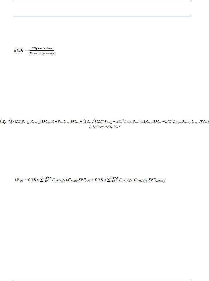
3 EEDI FORMULA
The EEDI is provided by the following formula:
With the following Notes:
The global fi factor may also be written:
 )
)
where each individual fi factor is explained under section 9 of this document.
If part of the normal maximum sea load is provided by shaft generators, the term  may be replaced by:
with the condition 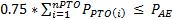
Where the total propulsion power is limited by verified technical means as indicated under section 6, the term  is to be
replaced by 75 percent of the limited total propulsion power multiplied by the average weighted value of (SFCME.CFME) and (SFCAE.CFAE)
Due to the uncertainties in the estimation of the different parameters, the accuracy of the calculation of the attained EEDI cannot be better than 1%.
Therefore, the values of attained and required EEDI have to be reported with no more than three significant figures (for instance, 2.23 or 10.3) and the checking of Regulation 20, chapter 4 of MARPOL Annex VI has to be verified in accordance with this accuracy.
I:\MEPC\64\INF-22.doc

MEPC 64/INF.22
Annex, page 4
4 FUEL CONSUMPTION AND CO2 EMISSION
The conversion factor CF and the specific fuel consumption, SFC, are determined from the results recorded in the parent engine Technical File as defined in paragraph 1.3.15 of the NOx Technical Code 2008.
The fuel grade used during the test of the engine in the test bed measurement of SFC determines the value of the CF conversion factor according to the table under 2.1of the IMO Calculation Guidelines.
SFC is the corrected specific fuel consumption, measured in g/kWh, of the engines. The subscripts ME(i) and AE(i) refer to the main and auxiliary engine(s), respectively. SFCAE is the power-weighted average among SFCAE(i) of the respective engines i.
For main engines certified to the E2 or E3 test cycles of the NOx Technical Code 2008, the
engine Specific Fuel Consumption (SFCME(i)) is that recorded in the test report included in a NOx Technical File for the parent engine(s) at 75% of MCR power.
For engines certified to the D2 or C1 test cycles of the NOx Technical Code 2008, the engine
Specific Fuel Consumption (SFCAE(i)) is that recorded in the test report included in a NOx Technical File for the parent engine(s) at 50% of MCR power or torque rating.
The SFC should be corrected to the value corresponding to the ISO standard reference conditions using the standard lower calorific value of the fuel oil (42,700kJ/kg), referring to ISO 15550:2002 and ISO 3046-1:2002.
For LNG driven engines for which SFC is measured in kJ/kWh, the SFC value should be converted to g/kWh using the standard lower calorific value of the LNG (48,000 kJ/kg), referring to the 2006 IPCC Guidelines.
For those engines which do not have a test report included in a NOx Technical File because its power is below 130 kW, the SFC specified by the manufacturer should be used.
At the design stage, in case of unavailability of test reports in the NOx Technical File, the SFC value given by the manufacturer with the addition of the guarantee tolerance should be used.
5 CAPACITY, POWER AND SPEED
5.1Capacity
The capacity of the ship is computed as a function of the deadweight as indicated under 2.3 of the IMO Calculation Guidelines.
For the computation of the deadweight according to 2.4 of the IMO Calculation Guidelines, the lightweight of the ship and the displacement at the summer load draught are to be based on the results of the inclining test or lightweight check provided in the final stability booklet. At the design stage, the deadweight may be taken in the provisional documentation.
5.2Power
The installed power for EEDI determination is taking into account the propulsion power and in general a fixed part of the auxiliary power, measured at the output of the main or auxiliary engine.
The total propulsion power is defined as 75% MCR of all main engines.
I:\MEPC\64\INF-22.doc
MEPC 64/INF.22
Annex, page 5
The total shaft propulsion power (power delivered to propellers PS) is conventionally taken as follows:
In this formula:
The value of PME(i) may be limited by verified technical means (see 6 below)
The total shaft propulsion power may be limited by verified technical means. In
particular an electronic engine control system may limit the total propulsion power, whatever the number of engines in function (see 6 below)
The auxiliary power can be nominally defined as a specified proportion of main engine power aiming to cover normal maximum sea load for propulsion and accommodation1. The nominal values are 2.5% of main engine power plus 250 kW for installed main engine power equal to or above 10 MW. 5% of PME will be accounted if less than 10 MW main engine power is installed. Alternatively, as explained below, the value for auxiliary power can be taken from the power balance table for the ship.
In addition, if shaft motors are installed, then in principle 75% of the shaft motor power is accounted for in the EEDI calculation. Detailed explanation about this is given in section 6.
For a ship where the PAE value calculated by paragraph 2.5.6.1 or 2.5.6.2 of the IMO Calculation Guidelines is significantly different from the total power used at normal seagoing operations, as an option if the difference leads to a variation of the computed value of the EEDI exceeding 1%, the PAE value could be estimated by the electric power (excluding propulsion) in conditions when the ship is engaged in a voyage at reference speed (Vref ) as given in the electric power table (EPT), divided by the average efficiency of the generator(s) weighted by power.
5.3Speed Vref
The speed Vref is the ship speed, measured in knots, verified during sea trials and corrected to be given in the following conditions:
in deep water
assuming the weather is calm with no wind, no current and no waves
in the loading condition corresponding to the Capacity
at the total shaft propulsion power defined in 5.2 taking into account shaft generators and shaft motors
6 SHAFT GENERATOR AND SHAFT MOTOR
6.1Introduction and background
Ships need electrical power for the operation of engine auxiliary systems, other systems, crew accommodation and for any cargo purposes. This electrical power can be generated by diesel-generator sets (gen-sets), shaft generators, waste heat recovery systems driving a generator and possibly by new innovative technologies, e.g. solar panels. Diesel-generator sets and shaft generators are the most common systems. While diesel-generator sets use a diesel engine powering a generator, a shaft generator is driven by the main engine. It is considered that due to the better efficiency of the main engine and efficiency of the shaft generator less CO2 is emitted compared to gen-set operation.
1 |
By paragraph 2.5.6.1 or 2.5.6.2 of the IMO Calculation Guidelines. |
|
I:\MEPC\64\INF-22.doc

MEPC 64/INF.22
Annex, page 6
The EEDI formula expresses the propulsion power of a vessel as 75% of the main engine power PME. It is also termed shaft power PS, which corresponds to the ship's speed Vref in the EEDI formula.
PAE - the auxiliary power - is also included in the EEDI formula. However, this power demand is largely dependent on loading and trading patterns and it must also incorporate safety aspects, for example, the provision of a spare generator set. As noted in section 5, the auxiliary power can generally be taken into account as a fixed proportion of the main engine power (i.e. nominally 2.5% plus 250kW)2.
The use of shaft generators is a well proven and often applied technology, particularly for high electrical power demands related to the payload e.g. reefer containers. Usually a ship design implements a main engine to reach the envisaged speed with some provision of sea margin. For the use of a shaft generator past practice and understanding was to install a bigger main engine to reach the same speed compared to the design without a shaft generator and to then have the excess power available from the main engine at any time for generation of electrical power. As a rule of thumb, one more cylinder was added to the main engine to cover this additional power demand.
The difficulty with this issue for calculation of the EEDI is that the excess power could be used to move the ship faster in the case where the shaft generator is not in use which would produce a distortion between ship designs which are otherwise the same.
The IMO Calculation Guidelines take these circumstances into account and offer options for the use of shaft generators. These options are described in detail, below.
Further, electric shaft motors operate similarly to shaft generators; sometimes a shaft generator can act as a shaft motor. The possible influence of shaft motors has also been taken into account in the IMO Calculation Guidelines and is also illustrated, below.
6.2Main engine power without shaft generators
The main engines are solely used for the ship's propulsion. For the purpose of the EEDI, the main engine power is 75 % of the rated installed power MCRME for each main engine:
PME(i) 0.75 MCRME(i)
6.3Main engine power with shaft generators
Shaft generators produce electric power using power from the prime mover (main engine). Therefore the power used for the shaft generator is not available for the propulsion. Hence MCRME is the sum of the power needed for propulsion and the power needed for the shaft generator. Thus at least a part of the shaft generator's power should be deductible from the main engine power (PME).
The power driving the shaft generator is not only deducted in the calculation. As this power is not available for propulsion this yields a reduced reference speed. The speed should be determined from the power curve obtained at the sea trial as explained in the schematic figure provided in paragraph 2.5 of the IMO Calculation Guidelines.
It has been defined that 75% of the main engine power is entered in the EEDI calculation. To induce no confusion in the calculation framework, it has therefore also been defined to take into account 75% of the shaft power take off / take in (as electrical power [kW] as displayed on the name plate of the shaft generator/motor).
2 |
c.f.: precise instruction in IMO Calculation Guidelines. |
|
I:\MEPC\64\INF-22.doc

MEPC 64/INF.22
Annex, page 7
For the calculation of the effect of shaft generators, two options are available.
6.3.1Option 1
For this option, PPTO(i) is defined as 75% of the rated electrical output power MCRPTO of each shaft generator. The maximum allowable deduction is limited by the auxiliary power PAE as
described in Paragraph 2.6 in the IMO Calculation Guidelines. Then the main engine power PME is:
PPTO i 0.75 MCRPTO i
PME(i) 0.75 MCRME(i) PPTO (i) with 0.75 PPTO i PAE
This means, that only the maximum amount of shaft generator power that is equal to PAE is deductible from the main engine power. In doing so, 75% of the shaft generator power must be greater than the auxiliary power calculated in accordance to Para. 2.6. of the IMO Calculation Guidelines.
Higher shaft generators output than PAE will not be accounted for under option 1.
6.3.2Option 2
The main engine power PME to be considered for the calculation of the EEDI is defined as 75% of the power to which the propulsion system is limited. This can be achieved by any verified technical means, e.g. by electronic engine controls.
PME(i) 0.75 PShaft,limit
This option is to cover designs with the need for very high power requirements (e.g., pertaining to the cargo). With this option it is ensured that the higher main engine power cannot be used for a higher ship speed. This can be safeguarded by the use of verified technical devices limiting the power to the propulsor.
For example, consider a ship having a 15 MW main engine with a 3 MW shaft generator. The shaft limit is verified to 12 MW. The EEDI is then calculated with only 75% of 12 MW as main engine power as, in any case of operation, no more power than 12 MW can be delivered to the propulsor, irrespective of whether a shaft generator is in use or not.
It should be noted that the guidelines do not stipulate any limits as to the value of the shaft limit in relation to main engine power or shaft generator power.
6.3.3The use of specific fuel oil consumption and CF-factor
Shaft generators are driven by the main engine, therefore the specific fuel oil consumption of the main engine is allowed to be used to the full extent if 75% of the shaft generator power is
equal to PAE.
In the case shaft generator power is less than PAE then 75% of the shaft generator power is calculated with the main engine's specific fuel oil consumption and the remaining part of the total PAE power is calculated with SFC of the auxiliaries (SFCAE).
The same applies to the conversion factor CF, if different fuels are used in the EEDI calculation.
6.4Total shaft power with shaft motors
In the case where shaft motor(s) are installed, the same guiding principles as explained for shaft generators, above, apply. But in contrast to shaft generators, motors do increase the total power to the propulsor and do increase ships' speed and therefore must be included in
I:\MEPC\64\INF-22.doc
MEPC 64/INF.22
Annex, page 8
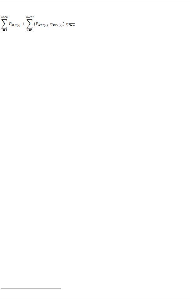
the total shaft power within the EEDI calculation. The total shaft power is thus main engine(s) power plus the additional shaft motor(s) power:
PME(i) PPTI (i),Shaft
Where:
PPTI (i),Shaft 0.75 PSM ,max(i) PTI (i)
Similar to the shaft generators, only 75% of the rated power consumption PSM,max (i.e. rated motor output divided by the motor efficiency) of each shaft motor divided by the weighted
average efficiency of the generator(s) Gen is taken into account for EEDI calculation.3
PPTI (i) |
|
0.75 PSM ,max(i) |
||
|
|
|
||
|
|
Gen |
|
|
A power limitation similar to that described above for shaft generators can also be used for shaft motors. So if a verified technical measure is in place to limit the propulsion output, only 75% of limited power is to be used for EEDI calculation and also for that limited power Vref is determined.
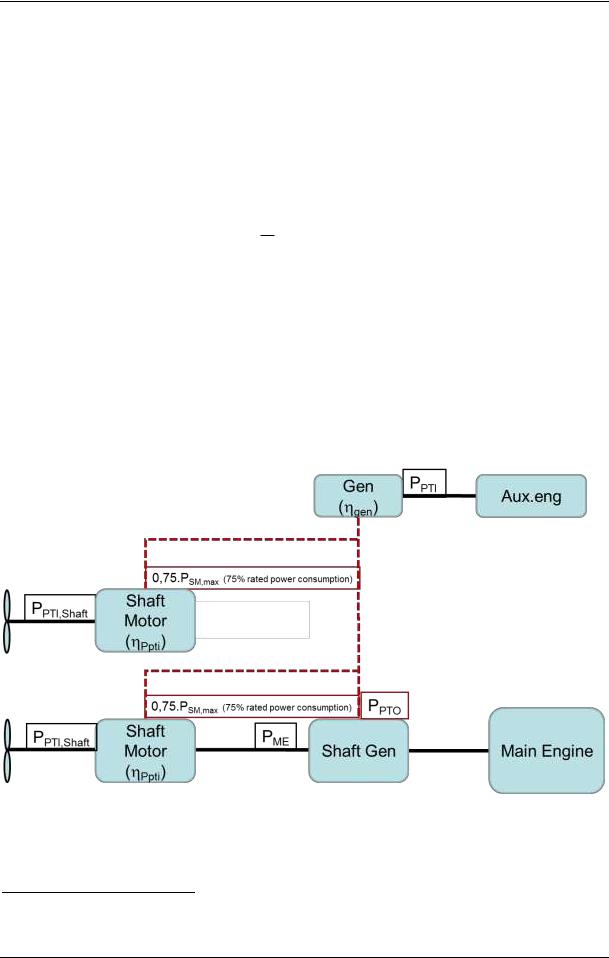
A diagram is inserted to highlight where the mechanical and electrical efficiencies or the related devices ( PTI and Generator's) are located:
Figure 1: Typical arrangement of propulsion and electric power system
3The efficiency of shaft generators in the previous section has consciously not been taken into account in the denominator as inefficient generator(s) would increase the deductible power.
I:\MEPC\64\INF-22.doc