

Chapter 14. Gas turbine engine starting systems
14.1. General information.
14.2. Structure of gas turbine engine starting systems.
14.3. Gas turbine engine start diagram. Characteristics of start stages.
14.4. Calculation of gas turbine engine starting system.
14.5. Types of aeroengine starting devices.
Literature: [1], p. 448 – 455; [4], p. 379 – 391; [6], p. 546 – 557; [8], p. 5 – 9, 16 – 34, 41 – 212; [20], p. 592 – 611, 615 – 617.
14.1. General information
14.1.1. Starting system designation
Starting system serves to transfer the engine from nonworking state or windmilling rating to idle rating. Idle rating is the rating with minimum possible thrust or power, at which all main engine units work stably. The GTE warm-up time at idle must not be less than two minutes.
14.1.2. Requirements to the starting system
Starting system should:
- provide reliable GTE ground and flight starting at minimum time without overstepping the limits of its main parameters (T*g, n) and at stable work of the main units;
- be automated and simple in control. Crew must only press the START button;
- be autonomous and have storage batteries or auxiliary gas turbine power unite on board (energy sources) for starting devices. On the other hand the GTE starting should be provided from aerodrome energy sources;
- be compact and have small weight.
14.2. Structure of gas turbine engine starting systems
The following systems provide GTE starting (Fig. 14.1):
- the engine rotor previous cranking (motoring) system;
- the starting fuel system;
- the ignition system;
- the fuel autostart control unit;
- the automatic control system of starting.
Engine rotor previous cranking system serves to motor the rotor to the rotational speed at which the GTE compressor raises an air pressure to the minimum value, which is enough for ignition and stable fuel burning in the combustion chamber.
The rotor cranking is performed with the help of the starting devices (starters). An energy source is the board auxiliary power unit (APU)or aerodrome sources. In engines with starting systems without starter the rotor cranking is performed by air supply to the GTE turbine through the special nozzles (Fig. 14.2).
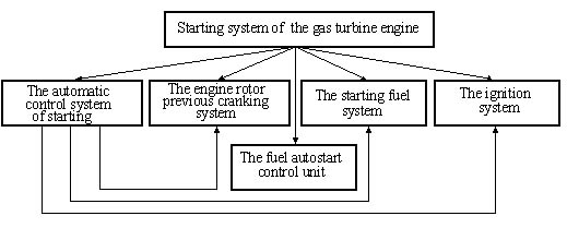
Fig. 14.1. Block diagram of GTE starting system
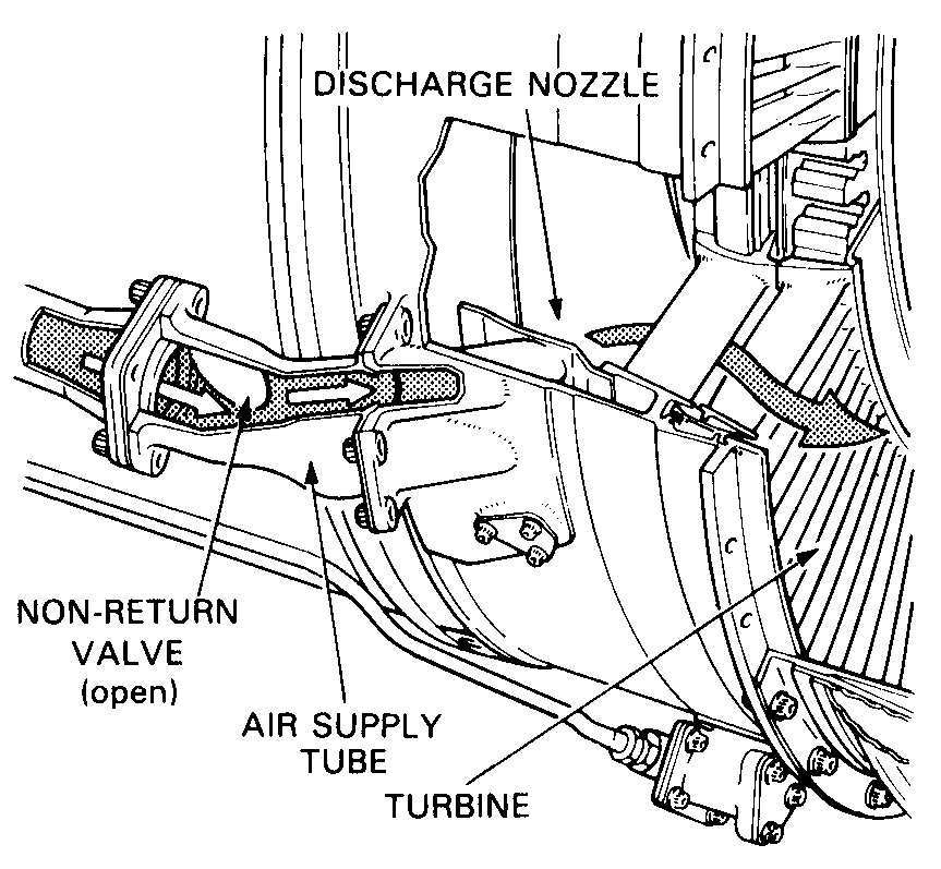
Fig 14.2. Air impingement starting
The starting fuel system supplies the starting fuel to nozzles of pilot burners at the given period of start. In most cases the starting fuel system is the starting fuel main line of fuel system (see Fig. 13.2, Fig. 13.3).
The ignition system provides ignition of the starting fuel. Its main components are:
- the electrical spark plugs;
- the induction vibrators, which supply alternating current with voltage 3…5 kV to the spark plugs. Usually every spark plug has its induction vibrator block.
The fuel autostart control unit automatically doses through ratio optimization between fuel and air in the engine. Optimization is dependent on requirement of start minimum duration without engine parameters leaving the limits and stable work of its main units.
Automatic control system of starting automatically turns on/off the starting system aggregates at the necessary start moments and when engine parameters reach given values. The main element of this system is automatic starting panel. In the GTE of I–IV-th generations this system is build according to the principle of programmed control. Programmed mechanism gives starting system aggregates turning on/off signals at the given starting moments.
In the GTE of V-th generation the electronic systems are used. The microprocessor computer engineering is applied there. Such systems control the starting system elements by the analysis principle of engine parameters, which may change depending on the concrete atmosphere conditions.