

4 Semester
1 Module Lighting Systems
Summary of Regulations
A main electric lighting system which provides illumination throughout those parts of the ship normally accessible to and used by passengers or crew shall be supplied from the main source of electrical power.
The arrangement of the main electric lighting system shall be such that a fire or other casualty in spaces containing the emergency source of electrical power, associated, transforming equipment, if any, the emergency switchboard and the emergency lighting switchboard will not render the main electric lighting system inoperative.
Lighting fittings shall be so arranged as to prevent temperature rises which could damage the cables and wiring, and to prevent surrounding material from becoming excessively hot.
All lighting and power circuits terminating in a bunker or cargo space shall be provided with a multiple-pole switch outside the space for disconnecting such circuits.
The Basics
Lighting of the ship's deck areas, engine room and accommodation to meet specified levels of illumination is provided by various light fittings designed to work safely in their particular locations. They also meet the safety and comfort levels of illumination required throughout a ship. Historically, the original application of electricity in ships was for lighting. Oil lanterns were a definite fire risk and the ship's lamp trimmer had great difficulty in maintaining his navigation lights in stormy weather.
The power ratings of the lamps used will vary from a few watts for alarm indicator lamps to a few kW for deck floodlights and searchlights (e.g. a Suez Canal Projector Light).
The amount of light falling on a particular area can be measured with an 'illuminance meter' or more commonly known as a 'lux meter'. This light meter is calibrated in units called lux (lx), where one lux is the illumination of one lumen per square metre (lm/m2) and a lumen is the unit of luminous flux. The minimum illumination standards required in a ship are given in Table 22.1.
Dirt on the lamp reflector and the lamp itself will also reduce its luminous efficiency. Group replacement of lamps is often considered by shipping companies to be more economical and convenient than individual replacement following a lamp's failure. Cleaning of the fittings can also be carried out during the replacement of lamps hence maintaining a high luminous efficiency.
Table 22.1 - Typical Illumination Levels Onboard a Ship
Incandescent Lamps
The most common lamp used for general lighting is the incandescent lamp, which is known as the simple filament type or a GLS (general lighting service) lamp. A current is passed through the fine wire tungsten filament, which raises its temperature to around 3000°C when it becomes incandescent and glows. The glass bulb is filled with an inert gas such as nitrogen or argon, which helps to reduce filament evaporation. This ensures an operating life expectancy of about 1000 hours.
One variation of the basic lamp design has a special coiled-coil filament, which increases the life expectancy of low-power lamps (up to 150 watts), which are referred to as 'double-life' lamps. (Refer Figure 22.1). Specially reinforced construction lamps (rough service) have a tough filament for use in areas where shocks and vibration are expected - this type is useful with portable (hand) lamps. Other variations include - clear glass bulb, inside frosted glass bulb (pearl) to reduce glare, tubular construction, internal reflector lamps, decorative lamps and heating lamps.
Light Outputs (At 240V Supply)
For lighting in areas where high vibration is imminent, single coil filament lamps are preferred, as they are more robust than the double wound type. (Refer Figure 22.1)
The luminous efficiency of 100W single - coil and coiled-coil lamps are as follows:
11.6 lumens per watt and 12.6 lumens per watt respectively; and Efficiency = Out put (lumens) Input (watts)
An increasingly popular variation of the incandescent lamp is the Tungsten-Halogen type. This construction has a gas-filled quartz tube or bulb, which also includes a halogen vapour such as iodine or bromine. When the filament is heated, evaporated tungsten particles combine with the halogen vapour to form a tungsten-halide.
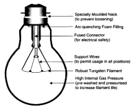
Figure 22.1 - Ordinary Filament Lamp (General Lighting Service Lamp)
At the high filament temperature, the tungsten vapour re-forms onto the filament. This regenerative process continues repeatedly creating a self-cleaning action on the inner surface of the glass tube or bulb. In an ordinary (GLS) lamp, the tungsten evaporation from the filament causes an internal blackening of the glass bulb which is overcome in the tungsten-halogen lamp. Two basic lamp forms for the tungsten-halogen design are the 'linear double-ended' lamp and the 'single - ended' lamp. Some tungsten - halogen details are mentioned in Tables 22.3 and 22.4.
Refer Figure 22.2 for a Linear - Double-ended Tungsten - Halogen lamp that is rated at 240V and has a life expectancy of 2000 hours.
|
Voltage (V) |
Power(W) |
Life (h) |
Light Output (lm) |
|
6 |
10 |
100 |
210 |
|
6 |
20 |
100 |
420 |
|
6 |
20 |
2000 |
350 |
|
12 |
100 |
2000 |
2150 |
|
12 |
50 |
2000 |
900 |
|
12 |
20 |
250 |
450 |
|
24 |
250 |
2000 |
5750 |
|
240 |
300 |
2000 |
5000 |
|
240 |
300 |
2000 |
8500 |
Table 22.4 - Tungsten - Halogen lamps - Power vs. Luminosity - Single-ended
Linear tungsten-halogen lamps must be used horizontally, otherwise the halogen vapour will concentrate at its lower end, which results in rapid blackening of the tube and a reduced operating life. Both are particularly useful for display, floodlighting and spotlighting.
Tungsten-halogen lamps must be carefully handled while being fitted. If the outside surface of the quartz tube or bulb is touched with dirty or greasy hands premature failure can occur due to fine surface cracks in the glass. Handle the tube by its ends only, or use a paper sleeve over the lamp during fitting. If accidentally handled, the lamp glass may be cleaned with a spirit solvent, carbon tetrachloride or trichloroethylene. (Refer Figure 22.2)
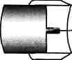
Figure 22.2 - Linear Tungsten-Halogen Lamp - Double-ended
Discharge lamps
The light output from a discharge lamp is generated by the flow of current in an electric arc between two electrodes through a gas and metal vapour inside a sealed glass bulb or tube. Mercury (as used in a fluorescent tube) and sodium are the most common metal vapours employed in discharge lamps. Low and high-pressure types of mercury and sodium lamps are available. A suitable voltage applied between the electrodes of a discharge lamp causes an arc discharge through the gas. This ionisation of the gas either creates visible light directly or by secondary emission* from a phosphor coating on the inside wall of the lamp glass.
Ionisation may also be caused by thermionic emission or by both - high voltage and thermionic emission.
The discharge lamp's current must be carefully controlled to maintain the desired light output and some form of current-limiting 'ballast' is required. This ballast is often an iron-cored inductor coil (choke) but special transformers and electronic regulator ballast circuits are also used. The ballast must 'match' the lamp (e.g. a 20W fluorescent tube must have a matching 20W ballast unit) in order to ensure correct lamp operation for high luminous efficiency and long life.
Hot Cathode Low Pressure Mercury Fluorescent Lamps
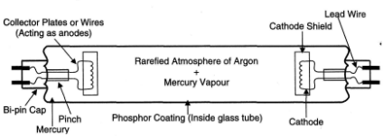
The most obvious example of this type is the popular fluorescent tube. It is classified as a MCF lamp (M - mercury, C - low pressure, F - fluorescent coating) (Refer Figure 22.3). The inside wall of the glass tube is coated with a fluorescent phosphor, which emits white or coloured light.
The coating is meant to absorb ultraviolet rays and convert them into visible light Variations of fluorescent material create different hues of white light. The most commonly known are given in Table 22.5. Fluorescent tubes are available in lengths from 150mm to 2400mm with power ratings from 4 Watts to 125 watts. The tube ends are usually fitted with bi-pin lamp caps or miniature bi-pin caps for the smaller tubes. Typical luminous efficiency for a fluorescent tube is approximately 70 lumens per watt with an average operating life of 5000 hours. It is capable of giving a glare-free, cool daylight effect.
|
Material |
Colour |
|
Calcium Tungstate |
Blue |
|
Magnesium Tungstate |
Blue-white |
|
Zinc Beryllium Silicate |
Yellow-white |
|
Cadmium Borate |
Pink |
|
Zinc Silicate |
Green |
Table 22.5 - Common Variants of Fluorescent Tubes
To 'strike' a fluorescent tube, its gas filling (usually argon or krypton) must be ionised by a voltage between its cathodes that is slightly higher than that required to maintain normal discharge. These electrodes may be coated with an oxide (e.g., barium oxide) to improve thermionic emission. If a suitable voltage is applied between the two electrodes a discharge strikes between them and the mains voltage is then sufficient to maintain the discharge.
This occurs in low pressure so that the lamp will function at a comparatively low temperature and so will not affect the fluorescent coating. The electrons from the electrode collide with the mercury atoms. This dislodges an electron from the atom making the mercury atom a positively charged ion. As the dislodged electron returns to the influence of the ion (i.e. the electron changes from one energy level to another) a certain amount of electromagnetic radiation (i.e. a photon) is given off in the form of ultra-violet light. These rays activate the fluorescent coating and the luminous surface provides a glare-free efficient light.
Two common methods are used to start the tube glowing:
The Switch-start Circuit,
The Transformer Quick-start Circuit.
A typical switch-start circuit is found in Figure 22.4. The starting action is initiated by a 'glow' type starter switch connected between the opposite ends of the tube. It contains two bimetallic electrodes in a small glass tube filled with Helium that prevents oxidation of the electrodes. When the supply voltage is applied to the circuit (ideally 220V), the entire voltage appears across the starter switch. A glow discharge occurs between the starter's contacts, which quickly heat up, bend and touch each other. This allows current to flow through the lamp cathodes which will cause the tube ends to glow before the tube actually strikes. The tube strikes when the starter switch re-opens as it cools down during its closed (non-glow) period.
When the starter switch opens, it interrupts an inductive (choke) circuit which produces a surge voltage (approximately 700 to 1000V, which can be about 3 to 4 times the applied voltage) across the tube which then 'strikes'. The tube glows brightly now and the reduced arc voltage across it is not sufficient to re-start the glow discharge in the starter; hence its contacts remain open. The voltage falls to about 120 V due to the effect of the supply frequency (normally 50 Hz) that causes a rise in impedance of the choke (as the inductive reactance XL = 2ITfL). If a d.c. source is used then a ballast resistor (which may be an incandescent light) must be used.
Thermionic emission is now maintained by ionic bombardment. In fact, in the normal operating condition the starter switch can be unplugged from its bayonet cap base and the lamp will function normally. The tube will not, of course, re-strike after switching off without the help of the starter.
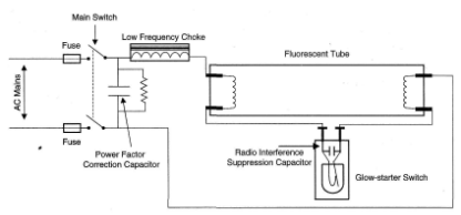
Figure 22.4 - Typical Glow-starter Switch Circuit
Two or three 'strikes' may be required to get the lamp working normally as the starter contacts may open before the cathodes are sufficiently heated. Such 'cold-striking' reduces the lamp's life by eroding the cathode material, which causes irregular lamp flashing. Severe blackening at the tube ends is a sure sign that its useful life is finished. Each time the starter's thermal contact closes, there are high-current surges through the choke coil, which increases its temperature. Excessive lamp flickering must, therefore, be swiftly corrected by replacement of the lamp or starter. More often than not it is the starter that is defective when such symptoms are observed. Only old or 'weak' lamps flicker due to their inability to bring about ionisation within.
Most choke coils are 'potted' in a thermosetting polyester compound within a steel case. While an earth fault is unlikely to occur within a choke, an open circuit is possible and can be simply checked with an ohmmeter. No repair of a choke is feasible so it must be completely replaced with an identically rated unit. Similarly, glow starters should only be replaced with an equivalent, which matches the wattage of the tube that it is to be used with. The commonly available glow starters have a dual rating i.e. 20 / 40 watts. Electronic starter switches are now available to eliminate flicker while switching on. These circuits are also called starter-less circuits or referred to as rapid start or instant start, where a drop in potential between the electrode and an earth strip is sufficient to ionise the gas adjacent to the electrode and this ionisation then spreads across the whole tube. An example of a transformer quick-start circuit is shown in Figure 22.5.
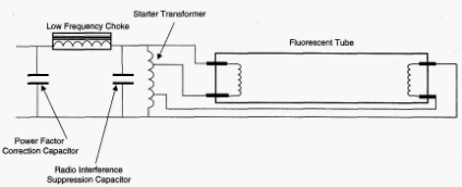
Figure 22.5 -Transformer Quick-start Circuit
The lamp discharge begins as soon as the cathodes reach their operating temperature. A capacitive effect between the cathodes and the earthed metalwork of the fitting ionises the gas and the tube 'strikes' very quickly. Most tubes have a conducting path through the phosphor coating or, alternatively, a special metal earth strip running between the end-caps assists the starting process. The transformer ballast gives an immediate start but some difficulty can occur with low ambient temperatures, low supply voltage and poor earthing. Many other variations of the quick-start circuit using transformers and resonant effects are used. Capacitors are used with a discharge tube for:
(i) Power factor correction (PFC)
(ii) Radio interference suppression (RIS)
The PFC capacitor is used to raise the power factor of the power supply to around 0.9 lagging and is connected in parallel with the power supply. Without this capacitor, the power factor may be as low as 0.2 lagging due to the choke's inductance. For a 125 W tube, a PFC value of about 7.2 µF is typical.
The ionisation process of the discharge causes radio interference from discharge tubes. This is suppressed by a capacitor fitted across the tube's ends. In glow-switch circuits, the RIS capacitor is actually fitted within the starter. RIS capacitor values are approximately 0.0005 (XF.
If the RIS capacitor in a glow-switch fails due to a short-circuit condition, the tube would not strike but would glow at its ends while the choke may overheat and eventually fail. A similar result would occur if the bi-metallic strips of the starter are welded together.
Advantages
S Greater efficacy, about 5 times the lumens per watt of tungsten filament
S About 5 times the life of incandescent lamps (5000 Hrs approximately)
Disadvantages
Higher initial cost
Power loss in a d.c plant due to the ballast resistor
Stroboscopic effect; two may be placed 90° out of phase
High Pressure Mercury Fluorescent Lamps
A typical high-pressure lamp and its circuit is shown in Figure 22.6. This type of lamp is coded as MBF (M = Mercury, B = high pressure, F = fluorescent coating). An additional suffix to lamp codes may be /U or /V meaning that the lamp is designed for fitting in a Universal or Vertical position respectively, e.g. MBF/U
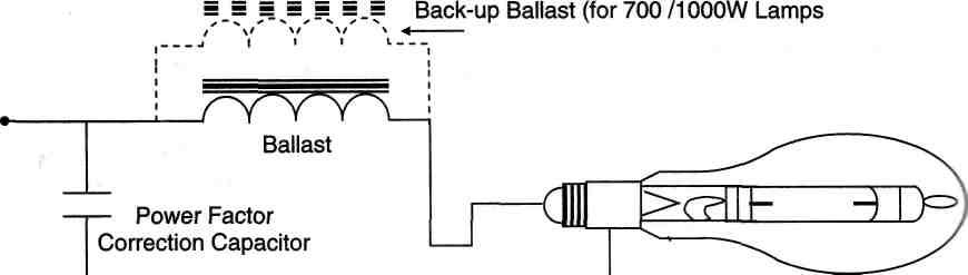
Figure 22.6 - High Pressure Mercury Fluorescent Lamp Circuit
The high pressure mercury lamp comes in sizes ranging from 50 to 1000 W and is fitted with Edison Screw (ES) or Goliath Edison Screw (GES) lamp caps. Its luminous efficiency is in the range of 40-60 lm/W with an average lifespan of around 7500 hours.
The lamp takes several minutes to achieve maximum brightness. It will not immediately re-strike when rapidly switched-off and then switched-on, because the vapour pressure (of several atmospheres) prevents this from happening. Re-striking will occur only when the discharge tube has sufficiently cooled down; ionisation of the gas occurs between a secondary electrode and one of the main electrodes fitted close to it, which warms up the tube and an arc now strikes between the main electrodes. Mercury vapour, which was condensed on the tube wall, now vaporises and the main arc passes through it. The secondary electrode ceases to function as the lamp pressure builds up.
Low Pressure Sodium Vapour Lamps
A low-pressure sodium lamp is coded as SOX (SO stands for 'sodium vapour', X stands for 'standard single-ended lamp of integral construction'). A typical lamp shape and its circuit are shown in Figure 22.7.
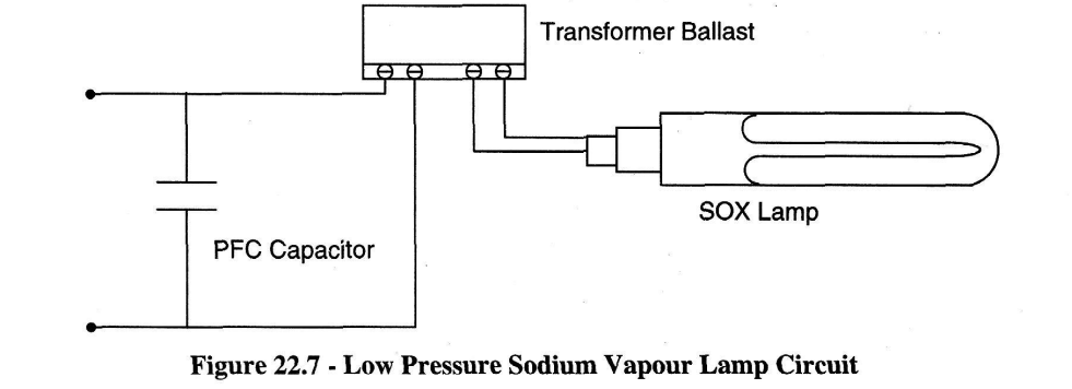
The lamp has a U-shaped arc tube containing metallic sodium and an inert gas such as neon. Common power ratings of the lamp are 35W, 55W, 90W, 135W, and 180W with luminous efficiencies in the range of 120-175 lm/W and with an average operating life span of 6000 hours.
The low-pressure sodium lamp needs a high voltage (480-650V) provided by a special transformer ballast circuit. When first ignited, the SOX lamp gives a red glow as the discharge is initially through the neon gas. As the lamp warms up, the sodium begins to evaporate to take over the discharge from the neon while the lamp colour changes from red to yellow. The time taken to reach maximum intensity is approximately 6-15 minutes.
High Pressure Sodium Vapour Lamps
A typical lamp and its circuit is shown in Figure 22.8. The basic lamp type is coded as SON (SO = Sodium vapour, N = high pressure), but two other variants are labelled as SON-T (a tubular clear glass type) and SON-TD (a tubular double-ended clear quartz type). The illumination by the SON lamp is wide-spread and delivers a golden-white light.
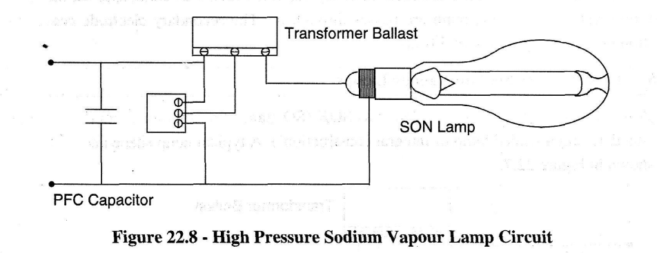
Lamp starting is achieved with the help of a high-voltage pulse from an igniter circuit, which ceases to function once the main arc has been struck. At least 5 minutes are required for the lamp to achieve its maximum intensity and will usually re-strike within 1 minute of extinction from a hot condition. SON lamp power ratings range between 70 and 1000W with corresponding luminous efficiencies being between 80 and 120 lm/W.
Effects of Voltage on the Performance of Lamps
Naturally, all lamps are designed to produce their rated luminous output at their rated voltage. An over-voltage on an incandescent lamp produces a brighter and whiter light because the filament temperature is increased. Its operating life is, however, drastically reduced. A mere 5% increase over its rated voltage will reduce the lamp life by 50%. Conversely, reduction in the voltage will increase the operating life of a GLS lamp but it produces a duller, reddish light. Lamps rated at 240V are often used in a ship's lighting system operating at 220V. This 'under-running' should more than double the lamp life.
Similar effects on light output and operating life apply to discharge lamps but if the supply voltage is drastically reduced (below 50%), the arc discharge ceases and they will not re-strike until the voltage is raised to nearly its normal value. Fluorescent tubes will begin to flicker noticeably as the voltage is reduced below their rated value.
The normal sinusoidal a.c. voltage waveform causes discharge lamps to extinguish at the end of every half cycle, i.e. every 10ms at 50Hz or every 8.33ms at 60Hz. Although this rapid light fluctuation is not detectable by the human eye, it can cause a stroboscopic effect whereby rotating machinery in the vicinity of discharge lamps may appear to be stationary or rotating slowly, which could be dangerous to operators.
There are a few methods to alleviate a stroboscopic problem. A few of them are:
(i) Use a mixture of incandescent and discharge lighting in the same area.
(ii) Use twin discharge lamp fittings with each lamp wired as a 'lead-lag' circuit, e.g. the lamp currents are phase-displaced so that they go through zero at different times; hence the net light output is never fully extinguished.
(iii) Where a 3-phase supply is available, connect adjacent discharge lamps to different phases (e.g. red, yellow and blue) so that the light in a given area is never extinguished.