

Inverse Definite Minimum Time (idmt) Relay
Accurate inverse time delay characteristics are provided by an induction type relay constructed similar to that of a domestic wattmeter or reverse power relay. Current in the main winding is obtained through a current transformer from the alternator input to the switchboard. The main winding is tapped and the taps are brought out to a plug bridge for selection of different settings (Refer Figure 13.7). Alternating current in the main winding on the centre leg of the upper laminated iron core produces a magnetic field that in turn induces current in the closed winding. The magnetic field associated with the closed winding is displaced from the magnetic field of the main winding and the effect on the aluminium disc is to produce changing eddy currents in it. The tendency for the disc to rotate is prevented by a helical restraining spring when normal current is flowing. Excessive current causes rotation against the spring. A moving contact on the spindle rotates about half a turn. The two fixed contacts are bridged and the tripping circuit is closed.

Figure 13.7 - Overload Relay - (Inverse Definite Minimum Time Relay)
The speed of rotation of the disc (through the half-turn) depends on the degree of over-current. Resultant inverse time characteristics are such as shown in Figure 13.8.
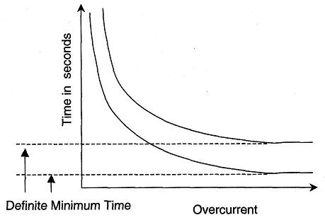
Figure 13.8 - Resultant Inverse Time Characteristics of the IDMT Relay
In many instances of over-current, the IDMT relay will not reach the tripping position, as the excess current will be cleared by other means. The characteristic obtained by the relay is one with a definite minimum time and this will not decrease regardless of the amount of over-current. Minimum time, however, can be adjusted by changing the starting position of the disc.
Breakers of alternators have instantaneous short-circuit current trips in addition to IDMT relays (or other types). In the event of a very large over-current, these rapidly trip the breaker. Without an instant trip, high fault current would continue to flow for the duration of the minimum time mentioned above.
Reverse Power Protection
Alternators intended for parallel operation are required to have a protective device, which will release the breaker and prevent motoring if a reversal of power occurs. Such a device would prevent damage to a prime mover, which has shut down automatically due to a fault such as loss of oil pressure. Reversal of current flow cannot be detected with an alternating supply but power reversal can, and protection is provided by a reverse power relay, unless an acceptable alternative protective device is fitted (instead of reverse power protection, electrical interlocks or contacts which will respond to various conditions, such as classing of the fuel or steam admission valve can also be used). The reverse power relay is similar in construction to an energy meter (Refer Figure 13.9).
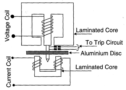
Figure 13.9 - Reverse Power Relay
The lightweight non-magnetic aluminium disc, mounted on a spindle, which has low-friction bearings, is positioned in a gap between two electromagnets. The upper electromagnet has a voltage coil connected through a transformer between one phase and an artificial neutral of the alternator output. The lower electromagnet has a current coil also supplied from the same phase through a transformer.
The voltage coil is designed to have high inductance so that the current in the coil lags the voltage by an angle approaching 90°. The magnetic field produced by the current similarly lags the voltage and also lags the magnetic field of the lower electromagnet. Both fields pass through the aluminum disc and cause eddy currents.
The effect of the eddy currents results in a torque being produced in the disc, normal power flow, trip contacts on the disc spindle are open and the disc bears against a stop. When power reverses, the disc rotates in the other direction, away from the stop, the contacts are closed so that the breaker trip circuit is energised. A time delay of 5 sec prevents reverse power tripping due to surges whilst synchronising.
Reverse power settings are 2% to 6% for turbine prime movers and 8% to 15% for diesel engines. A steam turbine over speed trip is connected to the circuit breaker trip because very little reverse power is required to cause over speeding. Thus the reverse power delay setting for steam turbine sets is between 1.5 - 3 % of full load settings.
Under-voltage Protection
Under-voltage protection on low-voltage systems is usually accomplished by an integral under-voltage release on the circuit breaker. Above 1000V, a separate relay would be required. It is commonly employed on marine systems:
To prevent closing of the circuit breaker when the generator is to be paralleled with other generators or the shore supply and the terminal voltage is less than 70%.
To ensure that loads, particularly motors are disconnected during a temporary loss of supplies. (Otherwise the generators could be tripped due to over-current conditions when supplies are restored owing to the total starting current of all connected motors).
To provide a back-up to short-circuit protection.
An under-voltage release is fitted to all generator breakers and some main feeder circuit-breakers. Its main function is to trip the breaker when a severe voltage dip (around 70%) occurs. The under-voltage release on a generator circuit-breaker prevents it from being closed when the generator voltage is very low or absent.
As an example of providing a back-up to short-circuit protection, let us assume that during generator paralleling procedures, an attempt was made to close the wrong circuit-breaker - the circuit-breaker of a stopped (and dead) generator; if this circuit-breaker was closed, the dead generator would be the equivalent of a short-circuit fault on the bus bars an cause a blackout. The under-voltage relay then prevents the closure of the circuit-breaker of dead generator.
The under-voltage trip on the generator breaker must not be operated if a feeder fault occurs. Consequently, it must be 'time-delayed' to permit the prior operation of feeder protection circuits. A time delay is also necessary to prevent operation when voltage transients occur during load-switching or synchronising. A voltage setting in excess of 80% would not normally be adopted because of the possibility of the generator being 'lost' when starting large motors.
Under-voltage protection is also required for motor starters. The starter contactor normally provides this protection as it drops out when the supply voltage is lost or is drastically reduced. The starter circuit will not normally allow the motor to re-start when the voltage supply is restored except when special automatic re-starting facilities are provided. Under-voltage protection can be electromagnetic or electronic.
Checking and calibration of generator under-voltage relays can be done accurately by voltage injection. A known variable voltage is directly applied to the under-voltage relay to check (a) the voltage at which the relay 'pulls in' and (b) the voltage at which the relay ,out'.
Under-voltage relays of generators are usually 'slugged' to prevent spurious or ‘misance' tripping during transient voltage dips (typically 15%) caused by large motor-ting currents. Whether under-voltage protection can provide effective back-up protection under short-circuit conditions is debatable. Often only the voltage across two phases is monitored and therefore the majority of phase-to-phase faults would be detected only when developed into three-phase faults. It is notable that this form of protection is relatively uncommon in industrial systems except on motor feeders.