

Fundamentals of the Physics of Solids / 08-Methods of Structure Determination
.pdf8
Methods of Structure Determination
Symmetries of the regular crystalline arrangement of atoms manifest themselves in direction-dependent quantities such as elastic constants or electric conductivity. The measurement of such quantities therefore provides information about the symmetries of the crystal, and so, indirectly, about its structure. A full determination of the structure – the Bravais lattice as well as the atomic positions in the basis – nevertheless calls for a method by which the interior of the sample can be seen. This requires a radiation that penetrates relatively deeply into the material so that it should feel not only the atoms close to the surface. Its wavelength has to be comparable to interatomic distances, i.e., the dimensions of the primitive cell.
As we have seen, typical interatomic distances are a few angstroms, therefore the wavelength of the probing radiation has to be of the same order of magnitude. This corresponds to the X-ray region of the electromagnetic radiation spectrum. In 1912, using X-rays scattered by a crystal, M. von Laue1 and two co-workers, W. Friedrich and P. Knipping obtained a di raction pattern characteristic of interference. X-ray di raction has since become the classic method of crystal-structure determination, due in a large part to the works of W. H. Bragg and W. L. Bragg.2 The range of applications of X-ray di raction has been extended substantially with the appearance of synchrotrons providing high-intensity radiation of high-energy γ photons.
Besides X-ray di raction, elastic scattering of electrons or neutrons is also suitable for structure determination as it is fairly easy to produce su ciently intense electron and neutron beams of appropriate wavelengths. By slowing down neutrons from fission reactors or spallation sources to thermal energies it is possible to produce neutrons in the wavelength range of a few angstroms. In the case of electrons, beams of the above wavelength are produced by accelerating them to energies on the order of 100 eV. In the section on experimental
1See footnote on page 2.
2See footnote on page 2.
242 8 Methods of Structure Determination
methods we shall discuss the advantages and disadvantages of using each type of radiation.
Whether photons, electrons, or neutrons are scattered by condensed matter, besides its structure, other characteristics of the surface or bulk of the sample may also be revealed. This is because interaction with radiation may change the state of the sample, inducing a transition from its initial state into an(other) excited state. In this case the energy of the photons (electrons, neutrons) in the scattered beam is di erent from the energy of the particles in the incident beam. These inelastic processes provide information about the internal processes taking place inside the sample, and thus their observation opens the way to studying the excited states of the system. To this end, one has to measure the spatial and energy distribution of the radiation scattered by the sample. Structure determination is much simpler: it just requires the measurement of the spatial distribution of the scattered beam emerging from a much more intense process, elastic scattering (di raction). In this chapter we first present the theory of di raction, and then discuss the methods used to observe di raction.
8.1 The Theory of Di raction
Owing to the greater availability of X-ray sources, X-ray di raction is more widely used for structure determination than neutron or electron di raction. For this reason, in what follows we shall speak of X-ray di raction, incident and scattered photons, although the condition presented below is valid for any type of radiation, it is concerned only with the wavelength. On the other hand, the penetration depth of the incident radiation into the sample and the relative intensity of the di racted beam both depend on the character of the radiation. Thus the di racted beam carries information either about the internal structure or the surface.
8.1.1 The Bragg and Laue Conditions of Di raction
Shortly after the first X-ray di raction patterns were recorded (1912), two di erent interpretations were proposed to account for them. W. L. Bragg (1913) advocated the view that atoms in crystals are arranged in parallel planes spaced at equal distances d, and X-rays are reflected specularly from them in accordance with the laws of reflection. As illustrated in Fig. 5.10, atoms can indeed be arranged into planes. Figure 8.1 shows a particular set of planes and the rays reflected from adjacent planes.
The phase di erence between rays reflected from subsequent planes depends on the spacing between the planes. Constructive interference occurs when the phase di erence between the rays reflected from adjacent planes is an integral multiple of 2π; otherwise the rays scattered by the planes interfere destructively. Thus scattered beams emerge only for some particular values of

8.1 The Theory of Di raction |
243 |
|
d |
|
|
|
d |
Fig. 8.1. Reflection of an atomic planes separated by incidence
X-ray beam of wavelength λ from a particular set of equal distances d. θ is the complement of the angle of
the angle of incidence. On the other hand, the direction of the crystal planes can be chosen in infinitely many di erent ways, as shown in Fig. 5.10. Then the condition for constructive interference can be satisfied for several of them for a fixed incoming beam, and thus scattered beams can emerge in several directions.
To determine the condition for interference, assume that the incident beam makes an angle θ with the selected crystal plane.3 According to the laws of reflection, the scattered beam makes the same angle with the plane, so the angle of deflection of the incident beam is 2θ. The path di erence between two rays reflected from adjacent planes is s = 2d sin θ, as it is readily seen in the figure. The integral multiples of this distance appear for waves reflected from subsequent layers. In terms of the path di erence s, constructive interference occurs when s is an integral multiple of the wavelength λ. Thus scattered beams emerge only when the condition
2d sin θ = mλ |
(8.1.1) |
is met by a family of crystal planes, where m is an integer. This is the Bragg condition for di raction. The intensity of the reflected beam has sharp peaks in the corresponding directions. They are called Bragg peaks.
In Laue’s formulation the appearance of a sharp di raction pattern is interpreted in terms of the interference of rays scattered by individual atoms rather than planes. Incident radiation is scattered by each atom, with an intensity that depends on the atomic species. The phase di erences between scattered waves depend on atomic positions and the direction of the incident and scattered beams. To determine this phase di erence assume that a radiation of wavelength λ is incident on the sample along the direction of the unit vector n. Di raction does not modify the wavelength of the ray, while its new direction will be denoted by n . Now consider two equivalent atoms in the
3In X-ray crystallography the above-defined θ is conventionally called the angle of incidence.
244 8 Methods of Structure Determination
crystal. Obviously, when one is chosen as the origin, the position vector Rn of the other has to be a lattice vector of the crystal. The geometry of incident and scattered beams is illustrated in Fig. 8.2.
k |
2 |
|
|
’ |
|
2 |
n |
’ |
|
n |
Rn |
k |
|
|
Fig. 8.2. Scattering of X-rays by two atoms of the crystal separated by a vector of the Bravais lattice
It can be immediately seen in the figure that the path di erence between the waves scattered by the atoms at lattice point Rn and at the origin is
s = Rn · n − Rn · n . |
(8.1.2) |
In terms of the wave vectors k = (2π/λ)n and k , the corresponding phase di erence is
φ = Rn · k − Rn · k . |
(8.1.3) |
The condition for constructive interference is that this phase di erence be an integral multiple of 2π for any lattice vector Rn of the crystal, that is,
Rn · (k − k ) = 2πm . |
(8.1.4) |
Recall (5.2.20): the product of any reciprocal-lattice vector G and any direct-lattice vector Rn is also an integral multiple of 2π. This means that the condition (8.1.4) for di raction is equivalent to the requirement that k−k should be a reciprocal-lattice vector,
k − k = G . |
(8.1.5) |
This relationship is called the Laue condition for di raction. For an incident beam of given direction and wavelength scattered waves emerge only in the directions that satisfy the above condition. We saw in Chapter 6 that for di raction this condition is in fact the consequence of discrete translational symmetry, and as such independent of any properties of the scattered beam.
Equation (8.1.5) may be written in another useful form by rearranging the terms and squaring the sides:
|k|2 − 2k · G + |G|2 = |k |2 . |
(8.1.6) |
As scattering is elastic, |k| = |k |, the condition for di raction is
8.1 The Theory of Di raction |
245 |
k · G = 21 |G|2 , |
(8.1.7) |
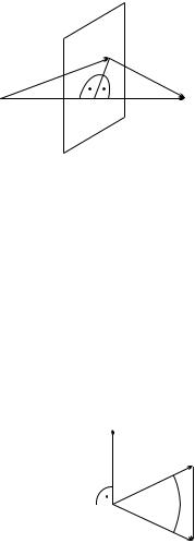
which is equivalent to the requirement that k − 12 G be perpendicular to G. Thus the condition for di raction is satisfied for incident beams whose wave vector points into a Bragg plane, i.e., the perpendicular bisecting plane of some vector G of the reciprocal lattice, as shown in Fig. 8.3.
k |
k’ k G |
G
k 1 2G G
Fig. 8.3. Illustration of the Laue condition (8.1.7). The wave vector k of the incident beam has to point into the perpendicular bisecting plane of some vector G of the reciprocal lattice
Although derived from the Laue condition, this relation is often called the Bragg condition for di raction. As it can be easily proved, the Bragg and Laue conditions are mathematically equivalent forms of the same requirement. Consider a situation in which the wave vectors of the incident and scattered beams satisfy condition (8.1.5) with a vector
Ghkl = m(hb1 + kb2 + lb3) |
(8.1.8) |
of the reciprocal lattice, where h, k, and l are relatively prime. The geometry of vectors k, k , and Ghkl is illustrated in Fig. 8.4.
|
Ghkl |
|
|
k' |
|
(hkl) |
|
|
|
Ghkl |
|
|
||
k
Fig. 8.4. Geometry of the wave vectors of the incident and scattered beams, the reciprocal-lattice vector satisfying the Laue condition, and the crystal plane perpendicular to it
As k and k are of equal length, their angle bisector is perpendicular to Ghkl = k −k . Since the reciprocal-lattice vector Ghkl is perpendicular to the

246 8 Methods of Structure Determination
lattice plane with Miller indices (hkl), the di raction can be considered as if the incoming beam were incident on and then reflected from the (hkl) plane at an angle θ. From the triangle shown in the figure the Laue condition can also be written as
|Ghkl| = 2|k| sin θ . |
(8.1.9) |
According to (5.2.26), the length of the reciprocal-lattice vector Ghkl can be expressed in terms of the spacing dhkl of the planes specified by the Miller indices (hkl). On account of the choice made in (8.1.8),
2π |
|
|Ghkl| = m dhkl . |
(8.1.10) |
By eliminating the wave number |k| in favor of the wavelength, (8.1.9) takes the form
m |
2π |
= 2 |
2π |
sin θ . |
(8.1.11) |
dhkl |
|
||||
|
|
λ |
|
||
This form of the Laue condition is obviously equivalent to the Bragg condition given in (8.1.1).
By measuring the angles where Bragg peaks appear, the spacings dhkl, and from them the lattice parameters can be determined. For example, in cubic crystals the lattice constant of the Bravais cell is related to the spacing by
1 |
= |
h2 + k2 + l2 |
, |
(8.1.12) |
|
d2 |
a2 |
||||
|
|
|
|||
hkl |
|
|
|
|
while in orthorhombic crystals the three lattice constants can be determined from
1 |
|
h2 |
|
k2 |
l2 |
|
|||||
|
= |
|
|
+ |
|
|
+ |
|
|
. |
(8.1.13) |
2 |
a |
2 |
b |
2 |
c |
2 |
|||||
d |
|
|
|
|
|
|
|
|
|||
hkl |
|
|
|
|
|
|
|
|
|
|
|
The unambiguous identification of the integers h, k, and l, and thereby the unambiguous determination of the lattice parameters calls for the measurement of the position of several interference peaks.
8.1.2 Structure Amplitude and Atomic Form Factor
In the previous subsection we derived the Bragg and Laue conditions from the wave nature of radiation using purely geometrical considerations, without any restrictions on the scattering potential. We only assumed that atoms are arranged in a periodic array, that the incident and scattered waves can be considered as plane waves, and that rays scattered by individual atoms or atomic planes interfere.
A more quantitative picture may be obtained by assuming that the interaction between the X-ray and the atom is given by a potential Ua(r). When the crystal has a monatomic basis, i.e., contains a single atom per primitive cell, the total potential is

8.1 The Theory of Di raction |
247 |
|
|
U (r) = Ua(r − Rn) . |
(8.1.14) |
Rn
Since photons interact with the electron shell of the atom, the potential is proportional to the electron density,
Ua(r − Rn) ρe(r − Rn) . |
(8.1.15) |
In the case of neutron scattering, neutrons interact with the nuclei or the magnetic moment of the electron cloud. Scattering by nuclei is described in terms of a local, Dirac delta-like Fermi pseudopotential,
2π 2 |
faδ(r − Rn) , |
|
Ua(r − Rn) = − mn |
(8.1.16) |
where fa has the dimension of length and is called the scattering length. The interaction governing magnetic scattering is proportional to the magnetic moment density.
To determine the scattered beam, we continue to assume that a plane wave of wave vector k is incident upon the sample, and the beam reaching the detector can be considered as a plane wave with wave vector k . The transition probability is proportional to the absolute square of the transition matrix element
k|U (r)|k = V |
U (r)e−i(k−k )·r dr . |
(8.1.17) |
|
1 |
|
|
|
In what follows, |k does not stand for a plane wave normalized with a factor 1/V −1/2 but for eik·r , thus the volume factor 1/V is absent from the matrix element.
When the potential is written as a sum of atomic potentials, the above matrix element can also be decomposed into the sum of contributions from individual atoms:
k|U (r)|k = e−i(k−k )·Rn Ua(r − Rn)e−i(k−k )·(r−Rn ) d(r − Rn) .
Rn
(8.1.18) The reader may recognize the k − k component of the Fourier transform of the atomic potential. Provided that this is identical for each atom, it can be taken out of the matrix element:
k|U (r)|k = Uk−k e−i(k−k )·Rn . |
(8.1.19) |
Rn |
|
|
|
The second factor on the right-hand side, |
|
e−i(k−k )·Rn |
(8.1.20) |
Rn

248 8 Methods of Structure Determination
is determined by the spatial distribution of the atoms. It turns out to be the Fourier transform of the atomic density function:
Rn |
e−i(k−k )·Rn |
= |
ρ(r)e−i(k−k )·r dr , |
(8.1.21) |
|
|
|
|
|
where |
|
|
|
|
|
ρ(r) = |
δ(r − Rn) . |
(8.1.22) |
|
|
|
Rn |
|
|
Introduction of the scattering vector K = k − k leads to |
|
|||
|
ρK = |
|
e−iK·Rn ; |
(8.1.23) |
|
|
|||
Rn
this quantity is called the structure amplitude.4
Note that up to this point we have not made use of the periodicity of the atomic arrangement, only the fact that the interaction of radiation with an atom is described by a common potential for each atom. Therefore the above definition of the structure amplitude – the Fourier transform of atomic density
– can be extended straightforwardly to noncrystalline materials.
Next, consider a crystal with p atoms arranged identically in each primitive cell. Let r1, r2, . . . , rp denote the atomic positions within a cell. The potential of the entire lattice is obtained by double summation: over the lattice vectors Rn specifying the primitive cell and over the position vectors rj of each atom within the cell,
|
|
|
U (r) = |
Uj (r − Rn − rj ) . |
(8.1.24) |
Rn |
rj |
|
Naturally, one must allow for di erent potentials for each atom of the basis. The matrix element is then
|
|
|
k|U (r)|k = |
Uj,K e−iK·(Rn +rj ) , |
(8.1.25) |
Rn |
rj |
|
where |
|
|
Uj,K = |
Uj (r)e−iK·r dr |
(8.1.26) |
is the Fourier transform of the potential of the jth atom. As mentioned above, for X-ray di raction the interaction potential is proportional to the density of electrons,
Uj,K ρej (r)e−iK·r dr . (8.1.27)
4Although many references use the term structure factor for this quantity, this name is customarily reserved for its square, |ρK |2, which appears in the cross section. This is in line with the definition of the same concept on page 18.
8.1 The Theory of Di raction |
249 |
This is why the expression on the right-hand side is called the atomic form factor ; in what follows, it will be denoted by AK . For spherically symmetric electron distributions
Aj,K = |
4πr2ρej (r) Kr dr . |
(8.1.28) |
|
|
|
sin Kr |
|
For magnetic scattering of neutrons, the density distribution of the electrons responsible for magnetism appears in the so-called magnetic form factor.
In crystalline materials, where each primitive cell is decorated with the same basis, the matrix element can be written as the product of two factors,
k|U (r)|k = |
e−iK·Rn |
Uj,K e−iK·rj . |
(8.1.29) |
|
|
|
|
Rn |
rj |
|
|
By exploiting the proportionality of the potential and the electron density once again, the second factor on the right-hand side may be written as
|
|
AK = Aj,K e−iK·rj . |
(8.1.30) |
rj
This quantity – or its complex conjugate – accounts for the arrangement of the atoms within a cell, and is therefore also called the structure amplitude. Note that the structure amplitude is just the Fourier transform of the total electron density of the atoms within the same cell,
AK = |
ρe,tot(r)e−iK·r dr , |
(8.1.31) |
|
where |
|
|
|
ρe,tot(r) = |
ρej (r) . |
(8.1.32) |
|
j
For nonmagnetic scattering of neutrons Uj,K should be replaced by the Fermi pseudopotential in (8.1.25). Since in this case neutrons are scattered by point-like nuclei, the atomic form factor is independent of K and proportional to the nuclear scattering length. The geometrical information contained in the phase factor is therefore weighted by the scattering lengths of individual atoms in the structure amplitude.
8.1.3 Di raction Cross Section
Having analyzed the matrix element showing up in the transition probability, we may now turn to the determination of the cross section for di raction. The di erential cross section for the scattering of an X-ray beam into the element of solid angle dΩ around the direction of k is obtained directly from the integration of the double di erential formulas given in Appendix E with respect to the energy variable:

250 |
8 Methods of Structure Determination |
|
|
||||||
|
|
dΩ |
= |
2π c |
2 |
k | f |U (r)|i |k |
2 , |
(8.1.33) |
|
|
|
dσ |
|
nk |
|
|
|
||
|
|
|
|
|
|
|
|||
|
|
|
|
|
|
|
|
|
|
where n is the index of refraction of the sample, while |i |
and |f are the |
||||||||
initial and final states of the scattering system. The same formula for neutron scattering is
|
dσ |
|
mn |
2 |
|
|
2 |
|
|
|
= |
k | f |U (r)|i |k |
. |
(8.1.34) |
|||||
|
dΩ |
2π 2 |
|
||||||
Scattering length was introduced in the context of neutron scattering on |
|||||||||
page 247. By analogy, the scattering amplitude f (r) defined through |
|
||||||||
|
|
|
|
|
2π c |
|
|
|
|
|
|
|
Ua(r) = − |
|
f (r) |
|
|
(8.1.35) |
|
|
|
|
nk |
|
|
||||
is often used instead of the atomic potential for other types of scattering as well. As f (r) has dimensions of length, it is often called the scattering length, too. Thus for X-ray and neutron di raction alike, the cross section of elastic scattering by a single atom is the absolute square of the Fourier transform fK of the scattering amplitude:
dσ |
= |fK |2. |
(8.1.36) |
dΩ |
If atoms in a bulk material all have the same scattering amplitude and are immobile at positions Rm, the cross section for di raction is
dσ |
|
|
|
|
= |fK |2 |
e−iK·(Rm −Rn). |
(8.1.37) |
dΩ |
|||
|
|
Rm ,Rn |
|
Note that the second structure-dependent factor on the right-hand side is – apart from a factor of 1/N – the Fourier transform of Γ (r) introduced in (2.1.16), which is related to the pair-correlation function, i.e., the expectation value of the product of two densities. Separation of the K = 0 term from Γ (K) left us with a quantity that we called the structure factor. Thus the cross section for di raction is proportional to the structure factor provided that the scattering amplitude is the same for each atom. It should be stressed that the validity of this result is not limited to crystalline materials. In crystals, however, the expression given in (8.1.37) is obtained even when the primitive cell contains several atoms, although in this case fK is replaced by a weighted sum of atomic scattering amplitudes,
fj,K e−iK·rj . (8.1.38)
rj
The directional distribution of the scattered beam is determined primarily by the second factor in (8.1.37), the structure factor. For di raction in crystals this leads to the condition that K = k − k should be equal to a reciprocallattice vector, as