

Labs / Lab4
.pdfLABORATORY WORK #4
MEASUREMENT OF THE HORIZONTAL COMPONENT
OF THE EARTH MAGNETIC INDUCTION
PhysicVirtualLab Software Package
LABORATORY WORK #4
MEASUREMENT OF THE HORIZONTAL COMPONENT OF THE EARTH MAGNETIC INDUCTION
1.AIM OF THE WORK:
Investigation of kinematical equations for straight line and uniformly accelerated motions;
Study of main dynamics equation of point particle and translational motion of rigid body.
TASKS:
Straight line velocity determination of the load using Atwood’s machine.
Determination of acceleration for the uniformly accelerated motion of the load.
Newton’s second law verification.
2.INTRODUCTION
English scientists William Gilbert, court physician of the Queen Elizabeth, in
1600 firstly assumed that the Earth is a magnet, the axis of which doesn’t match with the axis of rotation of the Earth. In any point of the space, surrounding the Earth, and on its surface there is the action of the magnetic forces. Hanged on the thread or fixed on the edge the magnetic needle is established in any point around the earth surface in a certain way, approximately in the direction from the north to south. This main fact proves the existence of the magnetic field of the Earth.
In 1635 Gellibrand discovered, that the field of the earth magnet changes slowly, and Edmund Halley made the first in the world the magnetic observation of the oceans and created first world magnetic maps (1702). In 1835 Gauss made the spherical harmonic analysis of the magnetic field of the Earth. He created first in the world magnetic observatory in Göttingen.
The accurate representation of the direction of the vector of magnetic induction of the Earth in given point one can get, fixed the magnetic needle so that it could rotate freely round the vertical and horizontal axes. It is possible to do, for example,
PhysicVirtualLabs Project Team, IITU
Copyright 2014

LABORATORY WORK #4
MEASUREMENT OF THE HORIZONTAL COMPONENT
OF THE EARTH MAGNETIC INDUCTION
PhysicVirtualLab Software Package
with the help of so called gimbal, shown on the figure 1 or with the help of special device declinometer (figure 2). The arrow sets in the direction of the vector of magnetic induction of the Earth.
Figure 1 – Gimbal [5.1]
PhysicVirtualLabs Project Team, IITU
Copyright 2014

LABORATORY WORK #4
MEASUREMENT OF THE HORIZONTAL COMPONENT
OF THE EARTH MAGNETIC INDUCTION
PhysicVirtualLab Software Package
Figure 2 – Magnetometer-declinometer of XVII century [5.1]
Earth magnetic field has the view like the globe is a magnet with the axis, directed from the north to the south approximately. In the northern Hemisphere all
magnetic lines of force converge in the point, situated on the |
north latitude |
||
and |
west longitude. This point called South magnetic pole of the Earth. In the |
||
southern Hemisphere the point of the converging of the lines of force lies on |
|||
south latitude and |
east longitude. It called the North magnetic pole of the |
||
Earth. It should be noted that converging points of the lines of force of the earth magnetic field lie not on the surface of the Earth, but under it. As we can see the magnetic poles of the Earth don’t coincide with it geographic poles.
The magnetic axis of the Earth, i.e. the line, connecting the two magnetic poles of the Earth, doesn’t go through its center and therefore is not the earth diameter. So, the Earth is the natural magnet, the poles of which are situated not far (~300 km) from the geographic poles. The magnetic pole of the Earth, which situated on the North, called the South magnetic pole, another one on the South correspondingly, is the North magnetic pole.
In present time it is often used the following definitions:
Geomagnetic poles are the points of the crossing of the magnetic axis of the Earth with its surface. Approximately one can consider that the Earth is the homogeneously magnetized sphere, the magnetic axis of which has the
angle |
with the rotation axis of the Earth. |
Geomagnetic latitude is the angle distance from the geomagnetic equator to the considered point of the earth surface. Geomagnetic latitude is measured along the big circuit, passing through the given point and geomagnetic poles.
Magnetic pole of the Earth is the point on the earth surface, where the magnetic needle is situated vertically. There are North and south magnetic poles of the Earth. The position of the magnetic poles of the Earth changes in time.
Dip-equator is the locus on the earth surface, where the magnetic needle is situated horizontally in relation on the surface. The dip-equator doesn’t coincide with the geographic equator.
PhysicVirtualLabs Project Team, IITU
Copyright 2014
LABORATORY WORK #4
MEASUREMENT OF THE HORIZONTAL COMPONENT
OF THE EARTH MAGNETIC INDUCTION
PhysicVirtualLab Software Package
Through the magnetic poles of the Earth it is possible to draw the lines of big circles, i.e. magnetic meridians, perpendicular to them the line of the big circle, i.e. dip-equator, and parallel to the last the lines of small circles, i.e. the magnetic parallels. Thus, to every point on the Earth will correspond not only geographical but the magnetic coordinates. The magnetic and geographical poles of the Earth don’t coincide with each other. The North magnetic pole lies in the southern Hemisphere near the coasts of Antarctica, and the South magnetic pole lies in the northern Hemisphere near the north coast of the Victoria Island (Canada).
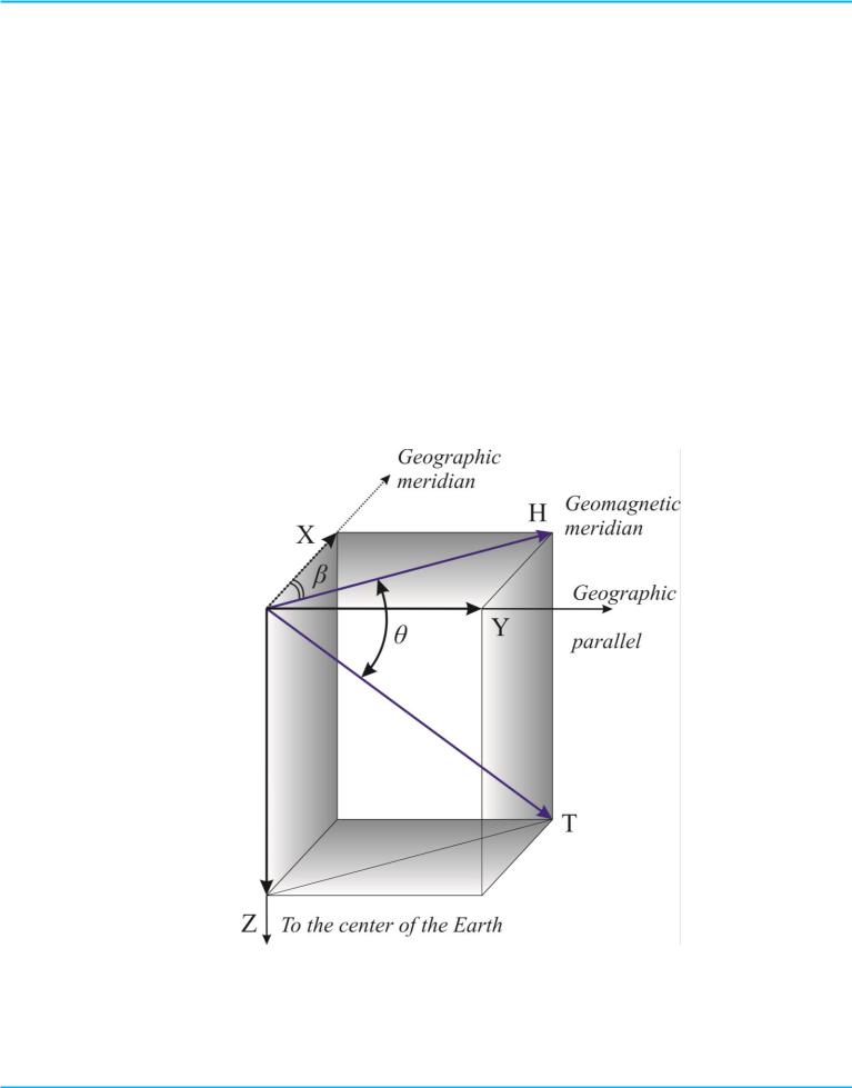
The full representation about the value of the magnetic field of the Earth in the given point it is possible to get, known the magnitudes of the three values, called the elements of the earth magnetism: the value of the horizontal component of the magnetic field induction, the value of the magnetic declination and the magnetic inclination.
Figure 3 – Elements of the earth magnetism
PhysicVirtualLabs Project Team, IITU
Copyright 2014

LABORATORY WORK #4
MEASUREMENT OF THE HORIZONTAL COMPONENT
OF THE EARTH MAGNETIC INDUCTION
PhysicVirtualLab Software Package
The magnetic declination (on the figure 3 is β) is the angle between the geographic and magnetic meridians in the point of the earth surface. The magnetic declination is the positive, if the north end of the magnetic needle is declined to the east from the geographic meridian and the negative, if the north end of the magnetic needle is declined to the west from the geographic meridian. The value of the magnetic declination is shown on the magnetic maps and used for the determination of the true meridian on the indication of the magnetic compass.
The magnetic inclination (on the figure 3 is θ) is the angle between the magnetic force line and the horizontal plane. On the magnetic poles of the Earth and in the
areas of large magnetic anomalies the magnetic inclination equals to |
. |
|
|
|
|
The Earth’s magnetic field В might be defined as the sum of |
the horizontal |
|
|
|
|
component В0 |
and vertical component Вn . |
|
Using the |
tangent-galvanometer, it is possible to define the |
magnetic field |
|
|
|
induction В0 measuring the electric current. The tangent galvanometer consists of the several vertically oriented circular coils. In the center of circular coils the magnetic pointer is arranged. The magnetic pointer should be sufficiently small to be sensitive to the coil’s electric current induction. The magnetic pointer may move around the
vertical axis, that is why it will be exerted only by the horizontal component of the
Earth’s magnetic field induction В0 . In the absence of the electric current the pointer
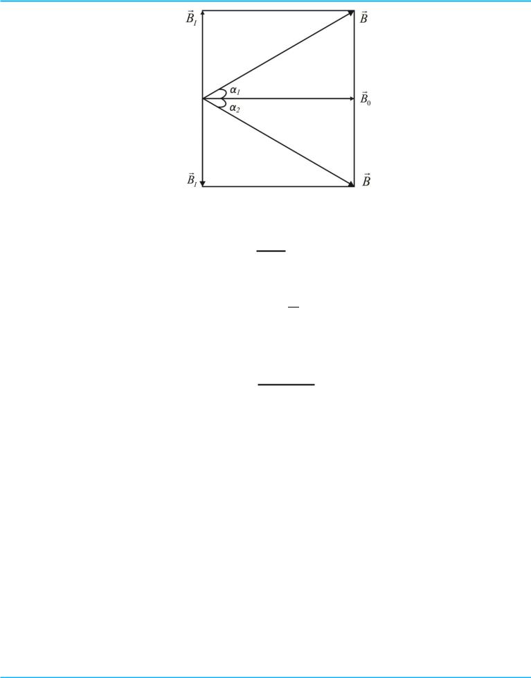
is oriented along the magnetic meridian ( В0 ) direction. The coils plane is set in of the magnetic meridian plane. After the electric current is switched the induced magnetic field is also acting on the pointer. The pointer is arranged along the resultant magnetic
|
|
|
field В , turning around by the angle α (Figure 4). Induced magnetic field |
ВI might be |
|
expressed as follows: |
|
|
. |
(1) |
|
PhysicVirtualLabs Project Team, IITU
Copyright 2014
LABORATORY WORK #4
MEASUREMENT OF THE HORIZONTAL COMPONENT
OF THE EARTH MAGNETIC INDUCTION
PhysicVirtualLab Software Package
Figure 4 – Vector diagram
If the number of coils is N then the induced magnetic induction is equal to:
, (2)
where N is the number of coils, is magnetic constant, R=15 cm. As a result we gain the following engineer formula:
. (3)
3. EXPERIMENTS DESCRIPTION
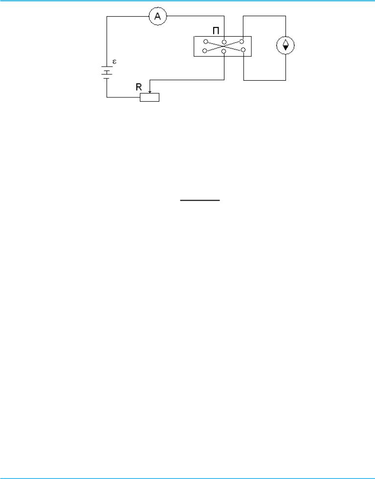
The experimental set consists of the electric current source, variable resistor, milliamperemeter, the key joint for tangent-galvanometer circuit. In the tangentgalvanometer the various number of coils are used (N = 2, 8 and 10).The accumulator battery is used to provide the source of the electric current. Amperemeter and variable resistance are used for measurement and variation of the electric current.
The circuit is combined according to the following scheme (Figure 5). The coil’s plane is arranged in the magnetic meridian’s plane. The angle α on the scale with nonius 1 min (error) is used.
PhysicVirtualLabs Project Team, IITU
Copyright 2014
LABORATORY WORK #4
MEASUREMENT OF THE HORIZONTAL COMPONENT
OF THE EARTH MAGNETIC INDUCTION
PhysicVirtualLab Software Package
Figure 5 – The work scheme
When the key is switched on the angle α1 is measured. Then the current direction is changed on the opposite one and the angle α2 is measured. In formula (3) the arithmetic mean of these angles is used to avoid systematic error of the experimental arrangement of the coil’s plane along the magnetic meridian:
The measured angle α is used in formula (3) for the В0 determination.
Procedure:
4.1Open the program.
4.2The laboratory work consists of the description, tests, exit windows.
4.3Clicking the window Theory you may be introduced with the experiment methodology, experimental set description and procedure of the experiment.
4.4Tests are used under the guidance of the course teacher. The tests are either to reveal level of the student’s readiness, start to do this work or to defend it.
4.5Clicking twice on the window Work, you will come to the exercise №1 connected with the scheme. After scheme is compiled push on the window Next Clarifying instructions are presented on the each step of the work execution.
4.6Next - exercise № 2-Measurement. In the center of the display outlined by the border you may input from your key-board the number of your measurements (from 3 up to 7) and push down the button Enter. The border which indicates the number of measurements will disappear. In the right bottom of your screen you will see the key. Clicking by your mouse on the key you will activate it-the dotted frame around it will appear. Next to switch
PhysicVirtualLabs Project Team, IITU
Copyright 2014

LABORATORY WORK #4
MEASUREMENT OF THE HORIZONTAL COMPONENT
OF THE EARTH MAGNETIC INDUCTION
PhysicVirtualLab Software Package
on or off the key you may you the buttons Up and Down. The instruction how to work with the key are also presented on the screen of your computer. Up means the current switching on one direction, Down means switching off the current, once again Down means the current switching in the opposite direction. In the case of the dot-ted border disappearance around the key you may activate it once again by clicking your mouse on the key. There is the table containing the measured data in the upper side of your screen. When the current is switched on (use the button Up) the magnetic pointer finds some definite position. You should wait for a while until the pointer will reach the steady position and correct data appearance in the table, then by clicking the button Down you will switch off the current, clicking on the button Down by the second time you will the direction of the electric current on the opposite direction. Next step is the following one. Wait for a while until the pointer will reach its steady state and correct data appearance on the table. Pushing the button Down you will switch off the electric current, pushing at the second time you will change the direction of the current on the opposite one, keeping its value the same as it was. Wait once again until the pointer will come to the steady position and data appearance in the table. Only after this you push down on the bottom Up to come the next measurement. All your measurements you should put down into the Table 1. The measurements were realized under the condition that number of coils is equal to N=2. After your measurements for the case are finished the number of your coils will be equal to 8, after it will be equal to 10.
4.7 All your data put into the Table 1.
Table 1
№ |
I, |
α1 |
α |
α |
tg |
B0 |
B0,av |
|
|
|
|
|
|
|
|
|
|
|
|
|
|
|
|
4.8 Pushing the button Next you will come to the table №1 filled by the data.
Compare these number with your data input in your notebook. After this you come to the definition of the following parameters α, tgα, B0. Absolute error of your experiment you will find using Student’s coefficients and final result should be presented in the following form:
PhysicVirtualLabs Project Team, IITU
Copyright 2014

LABORATORY WORK #4
MEASUREMENT OF THE HORIZONTAL COMPONENT
OF THE EARTH MAGNETIC INDUCTION
PhysicVirtualLab Software Package
( |
) |
4.9 Analyze the results of your experiment and make the conclusions.
4.QUESTIONS:
4.1What is the horizontal component of the vector of the Earth magnetic field induction?
4.2How does the angle of deflection of the magnetic needle α in dependence on the value of the current in the number of coils?
4.3How does the magnetic field of the Earth look like?
4.4What are the two main parts of the tangent-galvanometer?
4.5What is the aim of this work?
4.6What do the two magnetic fields act to the magnetic needle, placed in the center of the coil with the current?
4.7What is the equation for calculation of the magnetic field induction in the center of a circular current?
4.8What is the direction of the vector of the magnetic field induction in the center of the circular current?
4.9What is the position relative to each other the magnetic field of the coil in the tangent-galvanometer and horizontal component of the magnetic field of the Earth?
5.REFERENCES:
5.1R.G. Polozkov. Magnet field of the Earth. Methodological requirements to the laboratory work. SPb.: Izd-vo SPbGPU, 2007. 15 p.
5.2Raymond A. Serway, John W. Jewett Physics for Scientists and Engineers, 2006.
5.3Irodov I.E. Fundamental laws of mechanics, 2001.
PhysicVirtualLabs Project Team, IITU
Copyright 2014