

RADIO AIDS
.pdf23 OCT 09 |
RADIO AIDS |
EH-I |
TABLE OF CONTENTS
Limited or special coverages may not contain all items, but that material which is included should be arranged in the order outlined.
TABLE OF CONTENTS ................................................................................................................................ |
EH-I |
|
RADIO DATA - GENERAL |
|
|
GENERAL INFORMATION ....................................................................................................................... |
11 |
|
Frequency Bands .................................................................................................................................. |
11 |
|
Frequency Allocation............................................................................................................................. |
11 |
|
Navigation Aids ..................................................................................................................................... |
11 |
|
Airborne Stations .................................................................................................................................. |
11 |
|
117.975 – 137.0 Mhz Air Traffic Control Operations ............................................................................. |
12 |
|
Effective Range of Radio Transmissions............................................................................................... |
12 |
|
Types of Signal Emissions .................................................................................................................... |
13 |
|
SECTION 1. AIR NAVIGATION AIDS ....................................................................................................... |
15 |
|
1-1-1 |
General......................................................................................................................................... |
15 |
1-1-2 |
Nondirectional Radio Beacon (NDB)............................................................................................ |
15 |
1-1-3 |
VHF Omni-directional Range (VOR) ............................................................................................ |
15 |
1-1-4 |
VOR Receiver Check ................................................................................................................... |
16 |
1-1-5 |
Tactical Air Navigation (TACAN) ................................................................................................... |
17 |
1-1-6 |
VHF Omni-directional Range/Tactical Air Navigation (VORTAC) ................................................. |
17 |
1-1-7 |
Distance Measuring Equipment (DME)........................................................................................ |
17 |
1-1-8 |
Navigational Aid (NAVAID) Service Volumes ............................................................................... |
18 |
1-1-9 |
Instrument Landing System (ILS)................................................................................................. |
20 |
1-1-10 |
Simplified Directional Facility (SDF) ............................................................................................. |
25 |
1-1-11 |
Microwave Landing System (MLS)............................................................................................... |
25 |
1-1-12 |
NAVAID Identifier Removal During Maintenance ......................................................................... |
27 |
1-1-13 |
NAVAIDs With Voice..................................................................................................................... |
27 |
1-1-14 |
User Reports on NAVAID Performance........................................................................................ |
27 |
1-1-15 |
LORAN......................................................................................................................................... |
28 |
1-1-16 |
VHF Direction Finder.................................................................................................................... |
35 |
1-1-17 |
Inertial Reference Unit (IRU), Inertial Navigation System (INS), |
|
|
and Altitude Heading Reference System (AHRS) ........................................................................ |
35 |
1-1-18 |
Doppler Radar.............................................................................................................................. |
35 |
1-1-19 |
Global Positioning System (GPS) ................................................................................................ |
35 |
1-1-20 |
Wide Area Augmentation System (WAAS)................................................................................... |
46 |
1-1-21 |
GNSS Landing System (GLS)...................................................................................................... |
50 |
1-1-22 |
Precision Approach Systems other than ILS, GLS and MLS ....................................................... |
50 |
SECTION 2. AREA NAVIGATION (RNAV) AND REQUIRED NAVIGATION PERFORMANCE (RNP)..... |
81 |
|
1-2-1 |
Area Navigation (RNAV)............................................................................................................... |
81 |
1-2-2 |
Required Navigation Performance (RNP) .................................................................................... |
83 |
1-2-3 |
Use of Suitable Area Navigation (RNAV) Systems on Conventional Procedures and Routes..... |
84 |
SECTION 5. SURVEILLANCE SYSTEMS ............................................................................................... |
91 |
|
4-5-1 |
Radar ........................................................................................................................................... |
91 |
4-5-2 |
Air Traffic Control Radar Beacon System (ATCRBS) ................................................................... |
92 |
4-5-3 |
Surveillance Radar....................................................................................................................... |
96 |
4-5-4 |
Precision Approach Radar (PAR)................................................................................................. |
96 |
4-5-5 |
Airport Surface Detection Equipment — Model X (ASDE-X) ....................................................... |
96 |
4-5-6 |
Traffic Information Service (TIS)................................................................................................... |
97 |
4-5-7 |
Automatic Dependent Surveillance — Broadcast (ADS-B) ........................................................ |
103 |
4-5-8 |
Traffic Information Service — Broadcast (TIS-B) ....................................................................... |
105 |
DIRECTION FINDING PROCEDURES .................................................................................................. |
111 |
|
NAVIGATION AIDS LEGEND.................................................................................................................. |
121 |
|
© JEPPESEN SANDERSON, INC., 1993, 2009. ALL RIGHTS RESERVED.

EH-II |
RADIO AIDS |
23 OCT 09 |
|
TABLE OF CONTENTS |
RADIO DATA - LISTED BY IDENTIFIER |
|
Africa.................................................................................................................................................. |
A-31 |
Atlantic .............................................................................................................................................. |
AT-31 |
China............................................................................................................................................... |
CH-31 |
Europe ............................................................................................................................................... |
E-31 |
Eastern Europe ............................................................................................................................... |
EE-31 |
Middle East/South Asia................................................................................................................... |
ME-31 |
© JEPPESEN SANDERSON, INC., 1993, 2009. ALL RIGHTS RESERVED.

24 FEB 06 |
RADIO AIDS |
11 |
GENERAL INFORMATION
TheGENERAL INFORgeneralMATION information contained on the following pages is provided for use as ‘quick reference’. It has been compiled from a variety of sources. Additional information can be found elsewhere in the Radio Aids section.
FREQUENCY BANDS
Radio frequencies lie within a relatively narrow range of the electro-magnetic spectrum between approximately 10 kHz and 300 GHz. This range is divided into bands, more or less in accordance with the propagation characteristics of the frequencies. These bands are:
FREQUENCY ALLOCATION
Frequency allocation is established to provide a clear channeling between the various functions performed by aeronautical navaids and communications facilities. Although a general allocation plan is recognized on a world-wide basis, variations may occur within certain ranges. The listing below is intended to provide that allocation most generally used by civil operators.
108.0 |
- 111.975 MHz |
ILS localizer (on |
|
|
odd-tenths plus twentieth |
|
|
frequencies, 108.1, 108.3 |
|
|
etc.) |
108.0 |
- 111.975 MHz |
VOR (even tenths or even |
|
|
tenths plus a twentieth of |
|
|
MHz). |
111.975 - 117.975 |
VOR (even and odd |
|
MHz |
|
tenths of MHz). |
328.6 |
- 335.4 MHz |
ILS glide slope. |
960.0 |
- 1215.0 MHz |
DME and TACAN. |
1563.42 - 1587.42 |
GPS |
|
MHz |
|
|
AIRBORNE STATIONS
410 kHz |
International DF (outside |
|
continental USA). |
475 kHz |
Working frequency |
|
exclusively for aircraft on |
|
sea flights desiring an |
|
intermediate frequency. |
500 kHz |
International frequency |
|
for aircraft and ships over |
|
the seas. Transmission |
|
on this frequency (except |
|
for urgent and safety |
|
messages and signals) |
|
must cease twice each |
|
hour, for three minute |
|
periods beginning at 15 |
|
and 45 minutes past each |
|
hour. |
3281 kHz |
Lighter-than-aircraft. |
NAVIGATION AIDS
190 |
- 535 kHz |
Nondirectional Radio |
|
|
Beacon (low power) and |
|
|
Radio Range (low power). |
190 |
- 1750 kHz |
Non-directional Beacon |
|
|
(standard). |
Non-directional |
Marker Beacon. |
|
Beacon (standard). |
|
|
108.0 - 117.975 MHz |
VOR test facility (VOT). |
|
© JEPPESEN SANDERSON, INC. 2006. ALL RIGHTS RESERVED.

12 |
RADIO AIDS |
24 FEB 06 |
GENERAL INFORMATION
117.975 - 137.0 MHz AIR TRAFFIC CONTROL OPERATIONS
The minimum separation between assignable frequencies in the aeronautical mobile (R) service shall be 8.33 kHz.
It is recognized that in some regions or areas, 100 kHz, 50 kHz or 25 kHz channel spacing provides an adequate number of frequencies suitably related to international and national air services and that equipment designed specifically for 100 kHz, 50 kHz or 25 kHz channel spacing will remain adequate for services operating within such regions or areas. It is further recognized that assignments based on 25 kHz channel spacing as well as 8.33 kHz channel spacing may continue to co-exist within one region or area.
118 - 121.4 MHz |
International and National |
inclusive |
Aeronautical Mobile |
|
Services |
121.5 MHz |
121.5 MHz |
121.6 - 121.9917 |
International and National |
MHz inclusive |
Aerodrome Surface |
|
Communications |
122 - 123.05 MHz |
National Aeronautical |
inclusive |
Mobile Services |
123.1 MHz |
Auxiliary frequency SAR |
123.15 - 123.6917 |
National Aeronautical |
MHz inclusive |
Mobile Services with the |
|
exception of 123.45 MHz. |
123.45 MHz |
Worldwide air-to-air |
|
communications |
123.7 - 129.6917 |
International and National |
MHz inclusive |
Aeronautical Mobile |
|
Services |
129.7 - 130.8917 |
National Aeronautical |
MHz |
Mobile Services |
130.9 - 136.875 MHz |
International and National |
inclusive |
Aeronautical Mobile |
|
Services |
136.9 - 136.975 MHz |
International and National |
inclusive |
Aeronautical Mobile |
|
Services |
EFFECTIVE RANGE OF RADIO TRANSMISSION
The range of VHF transmissions is normally about 7% more than an actual line of sight, and can be determined by the formula:
Reserved for VHF air-ground data link communications.
© JEPPESEN SANDERSON, INC. 2006. ALL RIGHTS RESERVED.

24 FEB 06 |
RADIO AIDS |
13 |
GENERAL INFORMATION
Listed below is the appropriate range for VHF transmissions over flat terrain:
TYPES OF SIGNAL EMISSIONS
© JEPPESEN SANDERSON, INC. 2006. ALL RIGHTS RESERVED.

4 SEP 09 |
RADIO AIDS |
15 |
SECTION 1. NAVIGATION AIDS
Information about Radio Aids published in this section is extracted from the United States Federal Aviation Administration’s (FAA) Aeronautical Information Manual (AIM). It is provided for reference use only. The information is generally applicable around the world. Regional variations may exist. Within the section itself, additional references may be made to U.S. Federal Aviation Regulations (FARs). Relevant FARs can be obtained separately from Jeppesen, or they are available directly from the U.S. FAA by mail or via the internet.
1-1-1 GENERAL
a.Various types of air navigation aids are in use today, each serving a special purpose. These aids have varied owners and operators, namely: the Federal Aviation Administration (FAA), the military services, private organizations, individual states and foreign governments. The FAA has the statutory authority to establish, operate, maintain air navigation facilities and to prescribe standards for the operation of any of these aids which are used for instrument flight in federally controlled airspace. These aids are tabulated in the Airport/Facility Directory (A/FD).
b.Pilots should be aware of the possibility of momentary erroneous indications on cockpit displays when the primary signal generator for a ground-based navigational transmitter (for example, a glideslope, VOR, or nondirectional beacon) is inoperative. Pilots should disregard any navigation indication, regardless of its apparent validity, if the particular transmitter was identified by NOTAM or otherwise as unusable or inoperative.
1-1-2 NONDIRECTIONAL RADIO
BEACON (NDB)
a.A low or medium frequency radio beacon transmits nondirectional signals whereby the pilot of an aircraft properly equipped can determine bearings and “home” on the station. These facilities normally operate in a frequency band of 190 to 535 kilohertz (kHz), according to ICAO Annex 10 the frequency range for NDBs is between 190 and 1750 kHz, and transmit a continuous carrier with either 400 or 1020 hertz (Hz) modulation. All radio beacons except the compass locators transmit a continuous three-letter identification in code except during voice transmissions.
b.When a radio beacon is used in conjunction with the Instrument Landing System markers, it is called a Compass Locator.
c.Voice transmissions are made on radio beacons unless the letter “W” (without voice) is included in the class designator (HW).
d.Radio beacons are subject to disturbances that
may result in erroneous bearing information. Such disturbances result from such factors as lightning, precipitation static, etc. At night, radio beacons are vulnerable to interference from distant stations. Nearly all disturbances which affect the Automatic Direction Finder (ADF) bearing also affect the facility’s identification. Noisy identification usually occurs when the ADF needle is erratic. Voice, music or erroneous identification may be heard when a steady false bearing is being displayed. Since ADF receivers do not have a “flag” to warn the
pilot when erroneous bearing information is being displayed, the pilot should continuously monitor the NDB’s identification.
1-1-3 VHF OMNI-DIRECTIONAL
RANGE (VOR)
a.VORs operate within the 108.0 to 117.95 MHz frequency band and have a power output necessary to provide coverage within their assigned operational service volume. They are subject to line-of-sight restrictions, and the range varies proportionally to the altitude of the receiving equipment.
NOTE: Normal service ranges for the various classes of VORs are given in Navigational Aid (NAVAID) Service Volumes, paragraph 1-1-8.
b.Most VORs are equipped for voice transmission on the VOR frequency. VORs without voice capability are indicated by the letter “W” (without voice) included in the class designator (VORW).
c.The only positive method of identifying a VOR is by its Morse Code identification or by the recorded automatic voice identification which is always indicated by use of the word “VOR” following the range’s name. Reliance on determining the identification of an omnirange should never be placed on listening to voice transmissions by the Flight Service Station (FSS) (or approach control facility) involved. Many FSSs remotely operate several omniranges with different names. In some cases, none of the VORs have the name of the “parent” FSS. During periods of maintenance, the facility may radiate a T-E-S-T code
(– • ••• –) or the code may be removed.
d.Voice identification has been added to numerous VORs. The transmission consists of a voice announcement, “AIRVILLE VOR” alternating with the usual Morse Code identification.
e.The effectiveness of the VOR depends upon proper use and adjustment of both ground and airborne equipment.
1.Accuracy. The accuracy of course alignment of the VOR is excellent, being generally plus or minus 1 degree.
2.Roughness. On some VORs, minor course roughness may be observed, evidenced by course needle or brief flag alarm activity (some receivers are more susceptible to these irregularities than others). At a few stations, usually in mountainous terrain, the pilot may occasionally observe a brief course needle oscillation, similar to the indication of “approaching station.” Pilots flying over unfamiliar routes are cautioned to be on the alert for these
© JEPPESEN, 1994, 2009. ALL RIGHTS RESERVED.

16 |
RADIO AIDS |
4 SEP 09 |
SECTION 1. NAVIGATION AIDS
vagaries, and in particular, to use the “to/from” indicator to determine positive station passage.
(a)Certain propeller revolutions per minute (RPM) settings or helicopter rotor speeds can cause the VOR Course Deviation Indicator to fluctuate as much as plus or minus six degrees. Slight changes to the RPM setting will normally smooth out this roughness. Pilots are urged to check for this modulation phenomenon prior to reporting a VOR station or aircraft equipment for unsatisfactory operation.
1-1-4 VOR RECEIVER CHECK
a.The FAA VOR test facility (VOT) transmits a test signal which provides users a convenient means to determine the operational status and accuracy of a VOR receiver while on the ground where a VOT is located. The airborne use of VOT is permitted; however, its use is strictly limited to those areas/altitudes specifically authorized in the A/FD or appropriate supplement.
b.To use the VOT service, tune in the VOT frequency on your VOR receiver. With the Course Deviation Indicator (CDI) centered, the omni-bearing selector should read 0 degrees with the to/from indication showing “from” or the omni-bearing selector should read 180 degrees with the to/from indication showing “to.” Should the VOR receiver operate an RMI (Radio Magnetic Indicator), it will indicate 180 degrees on any omni-bearing selector (OBS) setting. Two means of identification are used. One is a series of dots and the other is a continuous tone. Information concerning an individual test signal can be obtained from the local FSS.
c.Periodic VOR receiver calibration is most important. If a receiver’s Automatic Gain Control or modulation circuit deteriorates, it is possible for it to display acceptable accuracy and sensitivity close into the VOR or VOT and display out-of-tol- erance readings when located at greater distances where weaker signal areas exist. The likelihood of this deterioration varies between receivers, and is generally considered a function of time. The best assurance of having an accurate receiver is periodic calibration. Yearly intervals are recommended at which time an authorized repair facility should recalibrate the receiver to the manufacturer’s specifications.
d.Federal Aviation Regulations (14 CFR Section 91.171) provides for certain VOR equipment accuracy checks prior to flight under instrument flight rules. To comply with this requirement and to ensure satisfactory operation of the airborne system, the FAA has provided pilots with the following means of checking VOR receiver accuracy:
1.VOT or a radiated test signal from an appropriately rated radio repair station.
2.Certified airborne check points.
3.Certified check points on the airport surface.
e.A radiated VOT from an appropriately rated radio repair station serves the same purpose as an FAA VOR signal and the check is made in much the same manner as a VOT with the following differences:
1.The frequency normally approved by the Federal Communications Commission is 108.0 MHz.
2.Repair stations are not permitted to radiate the VOR test signal continuously; consequently, the owner or operator must make arrangements with the repair station to have the test signal transmitted. This service is not provided by all radio repair stations. The aircraft owner or operator must determine which repair station in the local area provides this service. A representative of the repair station must make an entry into the aircraft logbook or other permanent record certifying to the radial accuracy and the date of transmission. The owner, operator or representative of the repair station may accomplish the necessary checks in the aircraft and make a logbook entry stating the results. It is necessary to verify which test radial is being transmitted and whether you should get a “to” or “from” indication.
f.Airborne and ground check points consist of certified radials that should be received at specific points on the airport surface or over specific landmarks while airborne in the immediate vicinity of the airport.
1.Should an error in excess of plus or minus 4 degrees be indicated through use of a ground check, or plus or minus 6 degrees using the airborne check, Instrument Flight Rules (IFR) flight shall not be attempted without first correcting the source of the error.
CAUTION: No correction other than the correction card figures supplied by the manufacturer should be applied in making these VOR receiver checks.
2.Locations of airborne check points, ground check points and VOTs are published in the A/FD.
3.If a dual system VOR (units independent of each other except for the antenna) is installed in the aircraft, one system may be checked against the other. Turn both systems to the same VOR ground facility and note the indicated bearing to that station. The maximum permissible variations between the two indicated bearings is 4 degrees.
© JEPPESEN, 1994, 2009. ALL RIGHTS RESERVED.

4 SEP 09 |
RADIO AIDS |
17 |
SECTION 1. NAVIGATION AIDS
1-1-5 TACTICAL AIR NAVIGATION (TACAN)
a.For reasons peculiar to military or naval operations (unusual siting conditions, the pitching and rolling of a naval vessel, etc.) the civil VOR/Distance Measuring Equipment (DME) system of air navigation was considered unsuitable for military or naval use. A new navigational system, TACAN, was therefore developed by the military and naval forces to more readily lend itself to military and naval requirements. As a result, the FAA has integrated TACAN facilities with the civil VOR/DME program. Although the theoretical, or technical principles of operation of TACAN equipment are quite different from those of VOR/DME facilities, the end result, as far as the navigating pilot is concerned, is the same. These integrated facilities are called VORTACs.
b.TACAN ground equipment consists of either a fixed or mobile transmitting unit. The airborne unit in conjunction with the ground unit reduces the transmitted signal to a visual presentation of both azimuth and distance information. TACAN is a pulse system and operates in the Ultrahigh Frequency (UHF) band of frequencies. Its use requires TACAN airborne equipment and does not operate through conventional VOR equipment.
1-1-6 VHF OMNI-DIRECTIONAL RANGE/TACTICAL AIR NAVIGATION (VORTAC)
a.A VORTAC is a facility consisting of two components, VOR and TACAN, which provides three individual services: VOR azimuth, TACAN azimuth and TACAN distance (DME) at one site. Although consisting of more than one component, incorporating more than one operating frequency, and using more than one antenna system, a VORTAC is considered to be a unified navigational aid. Both components of a VORTAC are envisioned as operating simultaneously and providing the three services at all times.
b.Transmitted signals of VOR and TACAN are each identified by three-letter code transmission and are interlocked so that pilots using VOR azimuth with TACAN distance can be assured that both signals being received are definitely from the same ground station. The frequency channels of the VOR and the TACAN at each VORTAC facility are “paired” in accordance with a national plan to simplify airborne operation.
1-1-7 DISTANCE MEASURING EQUIPMENT (DME)
a.In the operation of DME, paired pulses at a specific spacing are sent out from the aircraft (this is the interrogation) and are received at the ground station. The ground station (transponder) then transmits paired pulses back to the aircraft at the same pulse spacing but on a different frequency. The time required for the round trip of this signal
exchange is measured in the airborne DME unit and is translated into distance (nautical miles) from the aircraft to the ground station.
b.Operating on the line-of-sight principle, DME furnishes distance information with a very high degree of accuracy. Reliable signals may be received at distances up to 199 NM at line-of-sight altitude with an accuracy of
better than 1 /2 mile or 3 percent of the distance, whichever is greater. Distance information received from DME equipment is SLANT RANGE distance and not actual horizontal distance.
c.Operating frequency range of a DME according to ICAO Annex 10 is from 960 MHz to 1215 MHz. Aircraft equipped with TACAN equipment will receive distance information from a VORTAC automatically, while aircraft equipped with VOR must have a separate DME airborne unit.
d.VOR/DME, VORTAC, Instrument Landing System (ILS)/DME, and localizer (LOC)/DME navigation facilities established by the FAA provide course and distance information from collocated components under a frequency pairing plan. Aircraft receiving equipment which provides for automatic DME selection assures reception of azimuth and distance information from a common source when designated VOR/DME, VORTAC, ILS/DME, and LOC/DME are selected.
e.Due to the limited number of available frequencies, assignment of paired frequencies is required for certain military noncollocated VOR and TACAN facilities which serve the same area but which may be separated by distances up to a few miles.
f.VOR/DME, VORTAC, ILS/DME, and LOC/DME facilities are identified by synchronized identifications which are transmitted on a time share basis. The VOR or localizer portion of the facility is identified by a coded tone modulated at 1020 Hz or a combination of code and voice. The TACAN or DME is identified by a coded tone modulated at 1350 Hz. The DME or TACAN coded identification is transmitted one time for each three or four times that the VOR or localizer coded identification is transmitted. When either the VOR or the DME is inoperative, it is important to recognize which identifier is retained for the operative facility. A single coded identification with a repetition interval of approximately 30 seconds indicates that the DME is operative.
g.Aircraft equipment which provides for automatic DME selection assures reception of azimuth and distance information from a common source when designated VOR/DME, VORTAC and ILS/DME navigation facilities are selected. Pilots are cautioned to disregard any distance displays from automatically selected DME equipment when VOR or ILS facilities, which do not have the DME feature installed, are being used for position determination.
© JEPPESEN, 1994, 2009. ALL RIGHTS RESERVED.
18 |
RADIO AIDS |
4 SEP 09 |
SECTION 1. NAVIGATION AIDS
1-1-8 NAVIGATIONAL AID (NAVAID) SERVICE VOLUMES
a.Most air navigation radio aids which provide positive course guidance have a designated standard service volume (SSV). The SSV defines the reception limits of unrestricted NAVAIDs which are usable for random/unpublished route navigation.
b.A NAVAID will be classified as restricted if it does not conform to flight inspection signal strength and course quality standards throughout the published SSV. However, the NAVAID should not be considered usable at altitudes below that which could be flown while operating under random route IFR conditions (14 CFR Section 91.177), even though these altitudes may lie within the designated SSV. Service volume restrictions are first published in Notices to Airmen (NOTAMs) and then with the alphabetical listing of the NAVAIDs in the A/FD.
c.Standard Service Volume limitations do not apply to published IFR routes or procedures.
d.VOR/DME/TACAN Standard Service Volumes (SSV).
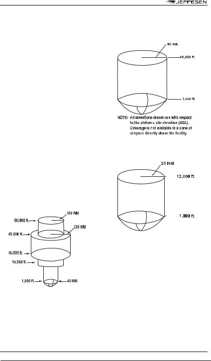
1.Standard service volumes (SSVs) are graphically shown in FIG 1-1-1, FIG 1-1-2, FIG 1-1-3, FIG 1-1-4, and FIG 1-1-5. The SSV of a station is indicated by using the class designator as a prefix to the station type designation.
EXAMPLE: TVOR, LDME, and HVORTAC.
FIGURE 1-1-1
Standard High Altitude Service Volume (See FIG 1-1-5 for altitudes below 1,000 feet).
FIGURE 1-1-2
Standard Low Altitude Service Volume (See FIG 1-1-5 for altitudes below 1,000 feet).
FIGURE 1-1-3
Standard Terminal Service Volume (See FIG 1-1-4 for altitudes below 1,000 feet).
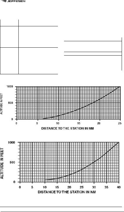
2.Within 25 NM, the bottom of the T service volume is defined by the curve in FIG 1-1-4. Within 40 NM, the bottoms of the L and H service volumes are defined by the curve in FIG 1-1-5. (See TBL 1-1-1.)
© JEPPESEN, 1994, 2009. ALL RIGHTS RESERVED.
4 SEP 09 |
RADIO AIDS |
19 |
SECTION 1. NAVIGATION AIDS
TABLE 1-1-1 VOR/DME/TACAN Standard
Service Volumes
e.Nondirectional Radio Beacon (NDB)
1.NDBs are classified according to their intended use.
2.The ranges of NDB service volumes are shown in TBL 1-1-2. The distances (radius) are the same at all altitudes.
TABLE 1 -1-2 NDB Service Volumes
FIGURE 1-1-4
Service Volume Lower Edge Terminal
FIGURE 1-1-5
Service Volume Lower Edge Standard High and Low
© JEPPESEN, 1994, 2009. ALL RIGHTS RESERVED.