

TERMINAL
.pdf16 MAY 08 |
TERMINAL |
EH-I |
TABLE OF CONTENTS
Below is a complete list of the standard contents of Airway Manual. Limited or special coverages may not contain all items, but that material which is included should be arranged in the order outlined.
TABLE OF CONTENTS ............................................................................................................................... |
|
EH-I |
VERTICAL DESCENT ANGLE REFERENCE TABLE........................................................................................ |
|
3 |
GRADIENT TO RATE TABLE |
|
|
Groundspeed in Knots to Feet per Nautical Mile .......................................................................................... |
|
5 |
Groundspeed in Knots to Gradient in Percentage ........................................................................................ |
|
7 |
HECTOPASCAL / MILLIBAR EQUIVALENT FOR AIRPORT ELEVATION....................................................... |
|
11 |
AFRICA |
|
|
Airport Operating Minimums Regulations for West Africa |
|
|
and Madagascar ......................................................................................... |
W. AFRICA & MADAGASCAR-1 |
|
EUROPE |
|
|
Airport Operating Minimums Regulations for France and French Overseas Territories................ |
FRANCE-1 |
|
MIDDLE EAST/SOUTH ASIA |
|
|
Airport Operating Minimums for India ................................................................................................ |
|
INDIA-1 |
TERMINAL CHARTS |
|
|
AREA, STAR, SID, NOISE, AIRPORT, Instrument Approach Procedures (IAP) |
|
|
© JEPPESEN 2002, 2008. ALL RIGHTS RESERVED.
2 DEC 05 |
TERMINAL |
3 |
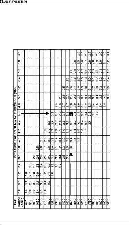
VERTICAL DESCENT ANGLE REFERENCE TABLE
VERTICALERTICAL DESCEN ANGLE REFERENCE TABLE DESCENT PLANNING
Vertical descent planning is a key component of the Constant Descent Final Approach (CDFA) concept. When not otherwise included on an instrument approach chart, this reference table provides a method to easily determine a vertical descent angle with respect to a defined Height at the FAF (Above Ground Level – AGL) and the Distance to the Runway Threshold (Nautical Miles – NM). The table in-
cludes a range of angles between 2.5 and 3.8 degrees.
To determine a vertical descent angle based upon a pre-defined combination of FAF Height (AGL) and Distance to Runway Threshold, match the FAF height (AGL) value in the left column to the corresponding Distance to Runway Threshold value in the top row. The value shown in the box where the two lines cross represents the vertical descent angle (in Degrees).
© JEPPESEN SANDERSON, INC. 2005. ALL RIGHTS RESERVED.
4 |
TERMINAL |
2 DEC 05 |
VERTICAL DESCENT ANGLE REFERENCE TABLE
EXAMPLE:
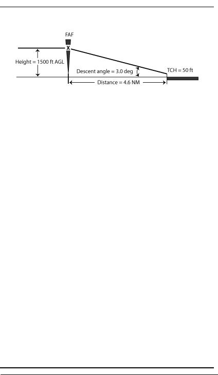
The table may also be used to determine a Height (AGL) at the FAF that would provide an optimum descent angle of 3.0 degrees. First, determine the Distance FAF to Runway Threshold (NM) in the top row, and then move down the table to the 3.0 degree value. Finally, move to the left to determine the optimum FAF Height (AGL). (Refer to Note 4 below).
IMPORTANT NOTES:
NOTE 1: Angles are predicated on an assumed
Threshold Crossing Height (TCH) of 50 feet.
NOTE 2: To determine the FAF Altitude as an Above Mean Sea Level value (AMSL), add the FAF Height (AGL value) and the Touchdown Zone Elevation (TDZE).
NOTE 3: Vertical descent angle information obtained from this table is for REFERENCE USE ONLY.
NOTE 4: ANY USE OF A HIGHER-THAN-PUB-
LISHED HEIGHT/ALTITUDE AT THE FINAL AP-
PROACH FIX (FAF) IS CONTINGENT UPON PRI-
OR APPROVAL BY AIR TRAFFIC CONTROL
AND/OR CONFORMANCE WITH APPLICABLE
OPERATING PROCEDURES.
© JEPPESEN SANDERSON, INC. 2005. ALL RIGHTS RESERVED.
21 APR 06 |
TERMINAL |
5 |
GRADIENT TO RATE TABLE
GROUNDSPEEDRADIENT TO RATE TABLE IN KNOTS TO FEET
PER NAUTICAL MILE
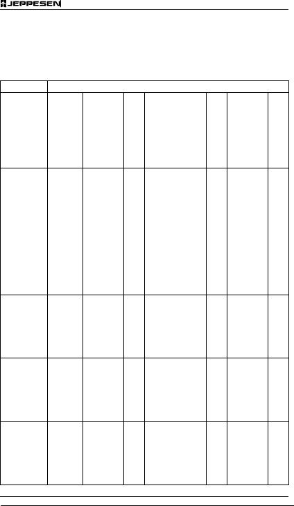
This table provides a rate of climb or descent in feet per minute below the GROUNDSPEED IN KNOTS for the gradient shown in FEET PER NAUTICAL MILE at the left. Table accuracy is within one foot per nautical mile. This table is for use in climbs, de-
scents from altitude and non-precision instrument approach procedures. This table does not consider the earth’s curvature as a factor. The earth’s curvature is considered when using fixed glide slope (ILS/PAR). Procedures utilizing a fixed glide slope have slightly higher figures to reflect the earth’s curvature.
© JEPPESEN SANDERSON, INC. 1987, 2006. ALL RIGHTS RESERVED.
6 |
TERMINAL |
21 APR 06 |
GRADIENT TO RATE TABLE
© JEPPESEN SANDERSON, INC. 1987, 2006. ALL RIGHTS RESERVED.
22 SEP 06 |
TERMINAL |
7 |
GRADIENT TO RATE TABLE
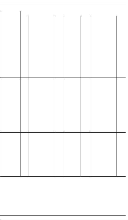
GROUNDSPEED IN KNOTS TO GRADIENT IN PERCENTAGE
This table provides a rate of climb or descent in feet per minute below the GROUNDSPEED IN KNOTS for the gradient shown in PERCENT (%) at the left. This table is for use in climbs, descents from altitude
and non-precision instrument approach procedures. Table accuracy is within four feet per nautical mile. This table does not consider the earth’s curvature as a factor. The earth’s curvature is considered when using fixed glide slopes (ILS/PAR). Procedures utilizing a fixed glide slope have slightly higher figures to reflect the earth’s curvature.
© JEPPESEN SANDERSON, INC. 1987, 2006. ALL RIGHTS RESERVED.

8 |
TERMINAL |
22 SEP 06 |
GRADIENT TO RATE TABLE
© JEPPESEN SANDERSON, INC. 1987, 2006. ALL RIGHTS RESERVED.
22 SEP 06 |
TERMINAL |
9 |
GRADIENT TO RATE TABLE
© JEPPESEN SANDERSON, INC. 1987, 2006. ALL RIGHTS RESERVED.

10 |
TERMINAL |
22 SEP 06 |
GRADIENT TO RATE TABLE
© JEPPESEN SANDERSON, INC. 1987, 2006. ALL RIGHTS RESERVED.

21 APR 06 |
TERMINAL |
11 |
HECTOPASCAL/MILLIBAR EQUIVALENT FOR AIRPORT ELEVATION
CORRECTIONHE TOPASCAL/MILLIBAR EQUIVALENT FOR AIRP RT ELEVATIONFACTOR
This table provides a correction factor in Hectopascals or Millibars for elevations on an airport. Application of the factor in this table will provide a QFE altimeter setting. To use the table, determine the
correction factor by finding the elevation in hundreds of feet in the left column and reading across to the nearest ten feet. For example 1220 feet equals -43.9. Subtract 43.9 from your current Hectopascal or Millibar altimeter setting and your altimeter shall read “zero” on the surface.
© JEPPESEN SANDERSON, INC. 1987, 2006. ALL RIGHTS RESERVED.