


9 |
|
Instrument Landing System (ILS) |
|
||
|
|
|
(ILS) System Landing Instrument 9
ILS Categories (ICAO)
ILS Facility Performance Categories (Ground Installation)
Category I
A category I ILS is one which provides guidance information from the coverage limit of the ILS to the point at which the localizer course line intersects the ILS glide path at a height of 200 ft (60 m) or less above the horizontal plane containing the threshold.
Category II
An ILS which provides guidance information from the coverage limit of the ILS to the point at which the localizer course line intersects the ILS glide path at a height of 50 ft (15 m) or less above the horizontal plane containing the threshold.
Category III
An ILS, which with the aid of ancillary equipment where necessary, provides guidance information from coverage limit of the facility to, and along, the runway surface.
Operational Performance Categories
The improvement in the ground installations allows guidance down to the surface of a runway and requires a corresponding improvement in the airborne equipment. An aircraft may be certified to operate to one of the following classifications:
Category I
An instrument approach and landing with :
•a DH not lower than 60 m (200 ft) and
•a Runway Visual Range (RVR) not less than 550 m.
Category II
A precision instrument approach and landing with
•a DH lower than 60 m (200 ft) but not lower than 30 m (100 ft) and
•a RVR not less than 300 m.
Category IIIA
A precision instrument approach and landing with:
•a DH lower than 30 m (100 ft), or no DH; and
•a RVR not less than 200 m.
Category IIIB
A precision instrument approach and landing with:
•a DH lower than 15 m (50 ft), or no DH; and
•a RVR less than 200 m but not less than 75 m.
158

Instrument Landing System (ILS) |
9 |
|
Category IIIC
No DH and no RVR limitations.
The acceptance of category II or III operations will depend on whether the following criteria are met:
•the aeroplane has suitable flight characteristics.
•the aeroplane will be operated by a qualified crew in conformity with laid down procedures.
•the aerodrome is suitably equipped and maintained.
•it can be shown that the required safety level can be maintained.
Errors and Accuracy
The Instrument Landing System has several limitations in that indications can be affected by:
•beam bends caused by atmospheric conditions
•scalloping caused by reflections which results in rapid fluctuations of the needles on the CDI/HSI which are impossible to follow; and
•beam noise generated by the transmitter or due to interference.
The pilot must be alert to the existence of potential problems and constantly cross-check the information which is being received.
•To minimize interference to the ILS transmissions, the rate of landings has to be kept relatively low, and also vehicle and aircraft movement must be restricted on the ground, especially during low visibility procedures.
•Pilot’s serviceability checks of the localizer and glide path may be checked by:
◦◦ ensuring the warning flags are not visible.
◦◦ the pilot monitoring the identification signals. Cessation of the Ident means that the ILS is unserviceable and the procedure must be discontinued immediately.
Factors Affecting Range and Accuracy
ILS Multipath Interference Due to Large Reflecting Objects
Multipath interference to ILS signals is dependent upon antenna characteristics plus any large reflecting objects, vehicles and fixed structures within the radiated signal coverage. Moving objects can degrade the directional signals to an unacceptable extent.
In order to protect the ILS signals from interference, protected areas are defined:
• ILS Critical Area. This is an area of defined dimensions about the localizer and glide path antennae where vehicles and aircraft are excluded during all ILS operations. It is protected because the presence of vehicles and/or aircraft inside its boundaries will cause unacceptable disturbance to the ILS signal-in-space.
Instrument Landing System (ILS) 9
159

9 |
|
Instrument Landing System (ILS) |
|
||
|
|
|
(ILS) System Landing Instrument 9
• ILS Sensitive Area This extends beyond the critical area and is where parking or movement of vehicles and aircraft is controlled to prevent the possibility of unacceptable interference to the ILS signal during low visibility ILS operations. The dimensions of this area depend upon the object creating the disturbance.
• Holding points |
Protection of ILS signals during category II and III operations may |
|
dictate that pre-take-off holding points are more distant from the |
|
runway than holding positions used in good weather. Such holding |
|
positions will be appropriately marked and will display signs ‘Category |
|
II/III Hold’; there may also be a bar of red stop lights. |
Weather
Snow and heavy rain attenuates the ILS signals thereby reducing the range and degrading the accuracy.
FM Broadcasts
FM transmitters have wide bandwidths and it is possible for such stations transmitting on frequencies just below 108 MHz to produce frequencies that overspill into the radio navigation band (108 to 117.975 MHz ) thereby causing interference with the ILS signals. Since the late 1990s FM suppression circuits have been mandatory in ILS receivers.
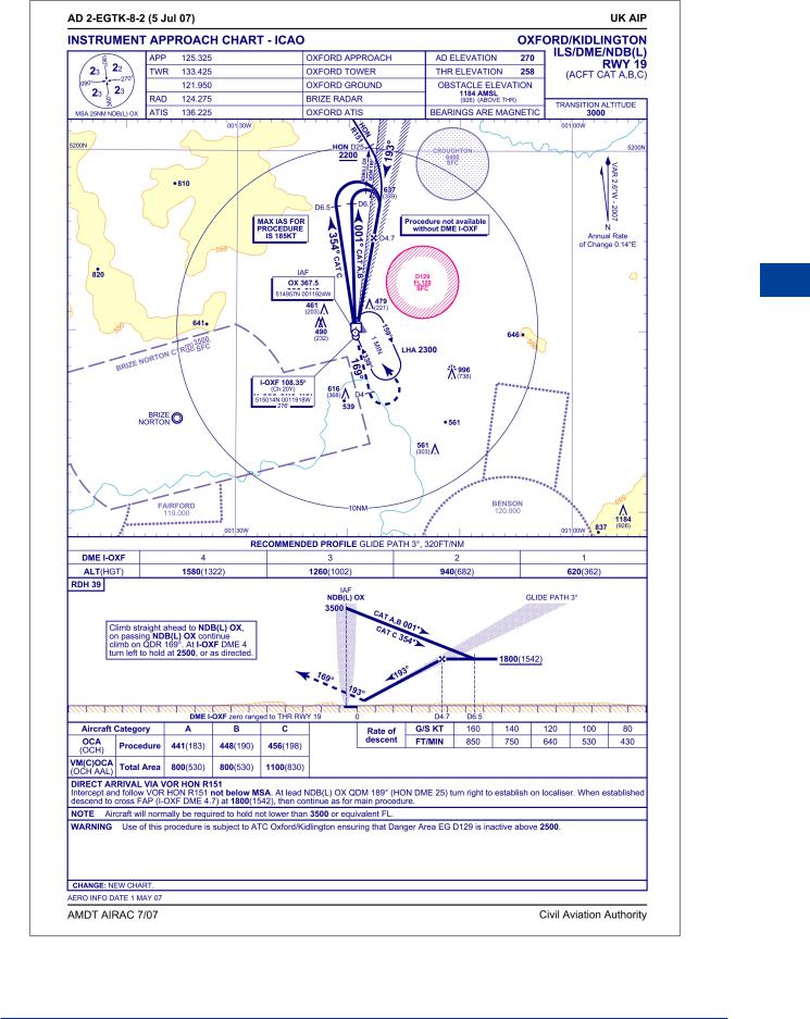
ILS Approach Chart
An Instrument Approach Chart for an ILS approach is shown in Figure 9.14. The instrument approach can be divided into the following 3 segments:
•Initial approach - procedure up to the IAF (initial approach fix).
•Intermediate - procedure between IAF and FAF (final approach fix).
•Final approach - procedure after FAF.
An aircraft should be at or above certain altitudes depending upon the sector from which it is approaching. These are known as sector safety altitudes (SSA) and are denoted in some form on the chart (circular in top left on this one).
Landing minima relates to the pilot’s decision height (DH) and the RVR. Before commencing the approach the pilot would normally be advised by ATC to check his landing minima.
160
Instrument Landing System (ILS) |
|
9 |
|
||
|
|
|
Instrument Landing System (ILS) 9
Figure 9.14 ILS approach to runway 19 at Oxford/Kidlington airport
161