

Maxwell_v16_L03_Static_Magnetic_Solvers
.pdf …Excitations
Excitation (3D)
Voltage : |
|
Voltage Drop: |
||
• |
Used in conjunction with material conductivity |
|
• |
Similar to the voltage definition |
|
to define current through a solid conductor |
|
• |
Can only be assigned to sheets which lie |
• |
Can only be assigned to faces or sheets that lie |
|
|
completely inside the conduction path |
|
on the boundary of simulation domain |
|
|
|
|
|
|
|
|
Current Density Terminal:
•Required to be defined if Current Density is defined
•Can be assigned to any 2D sheet which lies completely inside the conductor or Conductor faces that lie on the boundary of simulation domain
© 2013 ANSYS, Inc. |
May 21, 2013 |
11 |
Release 14.5 |

 e. Parameters
Parameters
–Three calculation parameters can be assigned for magnetostatic solver which are computed using magnetic field solution
–A parameter can be added by selecting the required object and selecting menu item Maxwell 3D/2D Parameters Assign
Force: |
|
Torque: |
||
• Calculates force acting on assigned object |
|
• |
Calculates torque on assigned object |
|
• |
Force can be Virtual or Lorentz |
|
• |
Torque can be Virtual or Lorentz |
• |
Lorentz can not be used for magnetic material |
|
|
|
|
|
|
|
|
Matrix:
•Calculates Inductance, resistance matrix
•Calculated matrix can be postprocessed based on defined groups
© 2013 ANSYS, Inc. |
May 21, 2013 |
12 |
Release 14.5 |

 f. Analysis Setup
Solution Setup
–The solution setup defines the parameters used for solving the simulation
–A Solution Setup can be added from the menu item Maxwell 3D/2D Analysis Setup Add Solution Setup
General Tab
•Name: sets the Name of the setup. Users can have multiple setups in the same design by repeating the procedure
•Maximum Number of Passes: Defines a limit to the number of adaptively refined passes that the solver performs
•Percent Error: Error goal for both Error Energy and Delta Energy.
•Solve Fields Only: Ignores any defined parameters if checked.
•Solve Matrix: Provides the options of calculating the matrix after the last solved pass or only if the solution converges.
Convergence Tab
•Refinement Per Pass: Defines the number of tetrahedral elements added during mesh refinement as a percentage of the previous pass
•Minimum Number of Passes: Defines the minimum number of adaptive passes before the solution stops - if there is a conflict, this value is over-ridden by Maximum Number of Passes
•Minimum Converged Passes: Defines the minimum number of converged adaptive passed before solution is stopped
© 2013 ANSYS, Inc. |
May 21, 2013 |
13 |
Release 14.5 |

 …Analysis Setup
Solution Setup
Expression Cache Tab:
•Enables users to define Output calculations at each adaptive pass or set an additional convergence criteria based on added parameters.
•Solution Setup should be completely defined first to enable adding Expression Cache variables
•Clicking on Add button enables users to define Output quantities which can be any defined parameters or derived quantities from Field Calculator
•Selecting the tab under Convergence will enable users to add the selected quantity as a convergence criteria
•Users can define the permissible change in output quantity in percentile or absolute value
•Output quantity will be evaluated at each Adaptive pass.
•If the change in defined output is less than specified value, the solution is considered to be converged provided that energy is already converged.
© 2013 ANSYS, Inc. |
May 21, 2013 |
14 |
Release 14.5 |

 …Analysis Setup
Solution Setup
Solver Tab
•Nonlinear Residual: Defines how precisely the nonlinear solution must define the B-H nonlinear operating points
•Enable Iterative Solver: Enables ICCG solvers (Direct is the default).
•Permeability Option: Allows nonlinear B-H operating points either to be calculated by the solver from Nonlinear B-H curve or to use frozen permeabilities From Link – the linked solution must have the exact same geometry as the current simulation
•Demagnetization Option: Allows the permanent demagnetization to be determined from the Nonlinear B-H curve or to use demagnetized values From Link - where the linked solution must the option “Compute Data for Link - Demagnetized operating points” checked and must have the exact same geometry
•Import Mesh: Allows the initial mesh to be imported from another solution – the linked solution must have the exact same geometry as the current simulation. Setup Link must be defined when selecting From Link or Import Mesh.
© 2013 ANSYS, Inc. |
May 21, 2013 |
15 |
Release 14.5 |

 g. Solution Process
Magnetostatic Solution Process
–The solution process is very automated. Once problem is completely defined, Maxwell steps through several stages of solution process as shown in diagram
–A Solution process can be launched from the menu item Maxwell 3D/2D
Analyze All
Initial Setup
Adaptive Solution
Nonlinear Convergence (Changing permeability)
Force/Torque Calculation
Solution Convergence ?
Yes |
No |
|
|
||
|
|
Refine Mesh |
Converged or Number |
|
|
|
|
|
of Passes |
|
|
|
|
|
Stop Field Solution
Calculate Parameters
© 2013 ANSYS, Inc. |
May 21, 2013 |
16 |
Release 14.5 |

 B. Eddy Current Solver
Eddy Current Solver
–Eddy current solver computes steady-state, time-varying (AC) magnetic fields at a given frequency
–This is a frequency domain solution and assumes frequency of the pulsating fields to be same throughout the domain
–3D Eddy Current Solver is a full wave solver and solves for displacement currents
–The source of the AC magnetic field can be a Sinusoidal AC current in conductors or time-varying external magnetic fields represented by external boundary conditions.
–Eddy Current solver utilizes adaptive mesh refinement technique to achieve best mesh required to meet defined accuracy level
Eddy Current Equations
– Following equations are solved with Eddy Current solver
|
1 |
|
|
|
|
|
H |
j H |
|
j |
||||
|
|
|
Maxwell 3D
|
1 |
|
j |
H |
|
j |
H |
||
|
|
|
|
|
|
|
|
Maxwell 2D
© 2013 ANSYS, Inc. |
May 21, 2013 |
17 |
Release 14.5 |

 a. Selecting the Eddy Current Problem
Selecting the Eddy Current Solver
–By default, any newly created design will be set as a Magnetostatic problem
–Specify Eddy Current Solver by selecting the menu item Maxwell 2D/3D
Solution Type
–In Solution type window, select Magnetic> Eddy Current and press OK
Maxwell 3D |
Maxwell 2D |
© 2013 ANSYS, Inc. |
May 21, 2013 |
18 |
Release 14.5 |

 b. Material Definition
Eddy Current Material Properties
– In Eddy Current simulations, the following parameters may be defined for a material:
Relative Permittivity:
•Relative Permittivity effects solution when displacement currents are considered in an object.
•Relative Permittivity can be Simple or anisotropic
Relative Permeability :
•Relative Permeability along with the Bulk Conductivity determine the time-varying magnetic properties of the material.
•Relative Permeability can be Simple and Anisotropic. In Maxwell 2D, nonlinear permeability is supported by obtaining a linearized permeability for each element from non-linear curve. Solution is still assumed to be linear.
Bulk Conductivity:
•Used in determining the current distribution in current carrying conductors and eddy currents from resulting magnetic field.
•Can be Simple or Anisotropic
Dielectric Loss Tangent:
•Defines the ratio of imaginary and real permittivities.
•Can be Simple or Anisotropic
Magnetic Loss Tangent:
•Defines the ratio of imaginary and real permeabilities.
•Can be Simple or Anisotropic
© 2013 ANSYS, Inc. |
May 21, 2013 |
19 |
Release 14.5 |
 …Material Definition
Eddy Current Material Properties
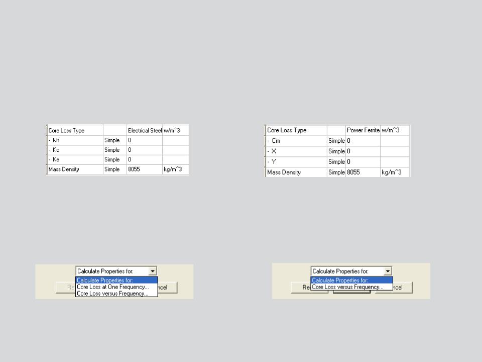
Core Loss Type:
•Enables users to define Core Loss properties based on selected Core Loss Type
•Core Loss Type can be either Electrical Steel or Power ferrite
•Core Loss Coefficients will change according to selected Core Loss type
p |
K |
|
f (B |
) |
2 |
K |
( fB |
) |
2 |
K |
( fB |
1.5 |
h |
|
|
) |
|||||||||
v |
|
m |
|
|
c |
m |
|
|
e |
m |
|
Core Loss Coefficient Calculations:
p |
|
C |
|
f |
x |
B |
y |
v |
m |
|
|
||||
|
|
|
|
m |
|||
•Maxwell provides tools to evaluate core loss coefficients based on core loss data provided by users
•Users can select tab at the bottom of View/Edit Material window and select the option
“Calculate Properties for”
For Electrical Steel |
For Power Ferrites |
© 2013 ANSYS, Inc. |
May 21, 2013 |
20 |
Release 14.5 |