

диафрагмированные волноводные фильтры / e14f84b0-a61f-4aeb-9f90-3d10859246b5
.pdfWideband balun bandpass filter explored for a balanced dipole antenna with
high selectivity
Gang Zhang, Jianpeng Wang and Wen Wu
A novel microstrip wideband balun bandpass filter (BPF) is presented for development of a balanced dipole antenna with wide operating band and high frequency selectivity. By utilising the standing-wave property of current distribution along a half-wavelength (λ/2) openended microstrip line, out-of-phase signals are ideally obtained at two output ports of a balun. Meanwhile, proper coupling topologies between the open-circuited λ/2 microstrip transmission line and the quadruple-mode resonators are selected to achieve a balun BPF with both characteristics of balanced performance and wideband filtering properties. A balun BPF operating at 1.65 GHz with 32% fractional bandwidth is at first designed. The derived results not only exhibit good performance with 0.49 dB amplitude imbalance and 7.2° phase imbalance, but also achieve high selectivity relying on two transmission zeros. Next, this balun BPF is integrated with a balanced dipole antenna with a flat shape towards wideband and high-selective radiation. Both simulated and measured results achieve higher than 10 dB return loss and 2.4 dBi radiation gain over a band of 1.4–1.9 GHz.
Introduction: The balun bandpass filter (BPF) that combines both the functions of the balun and bandpass filter is one of the most essential passive circuits for high integrated RF front-end systems. As its most attractive feature, it converts an input unbalanced single-ended signal into its balanced ones while maintaining the high frequency selectivity of a bandpass filter. Thus, researches on balun BPFs with compact size and good performance have been receiving increasing attention [1–5].
Using the multilayer technology, Zhang et al. proposed a balun BPF in [1]. In despite of the size reduction for this method, it suffers from a few drawbacks such as complicated geometry and design procedures. Meanwhile, several planar balun BPFs with simple structures have also been reported [2–5]. By employing the step-impedance resonators, a planar Marchand balun BPF is developed with dual passbands [2]. Nevertheless, the introduced grounding vias have resulted in an extra inductive effect and deteriorated the desired balun characteristics. In addition, a dual-mode resonator is introduced to realise a balun BPF with high selectivity and compact size in [3]. Yet, it is restrained in the loop-type dual mode resonator. Besides, a balun filter on the substrate integrated waveguide [4] was reportedly designed based on the coupled-resonator model. Recently, by utilising the inherent stand wave property of an open ended transmission line, a wideband balun BPF employing the triple-mode resonator with a stepped impedance stub is designed [5]. However, the operation bandwidth of this balun BPF needs further improvement while considering its practical application for the wideband antenna.
The primary motivation of this Letter is to propose a new wideband balun BPF on the open-type quadruple-mode resonators and to verify its feasibility in practical wideband application. To achieve the out-of-phase signals at two output ports, the proposed balun BPF is realised by utilising the standing-wave distribution on a λ/2 open-ended transmission line, which is then effectively integrated with the quadruplemode resonators to get wideband filtering performance. After the balun BPF is designed with good balanced performances and 3-dB FBW of about 32%, it is integrated with a balanced feed dipole antenna with flat shape, aiming to achieve wideband and high-selective radiation as expected. These properties predicted in theory are in final satisfactorily verified in experiment.
Proposed wideband BPF: Fig. 1 depicts the configuration of the proposed balun BPF (part 1) used for feeding a balanced dipole antenna with flat shape (part 2). As described in part 1, the unbalanced signal excited from port#1 firstly propagates along a λ/2 open-ended microstrip line, surrounded by a white dotted-line in Fig. 1. In this context, a standing wave of electric current is established along this open-ended line. More specifically, the voltage and electric field distribution along the λ/2 open-circuited line can be classified into two distinct regions in terms of out-of-phase and identical amplitude as illustrated in [6]. These inherent properties are utilised herein to form up an alternative balun.
The quadruple-mode resonator employed in this work is depicted in Fig. 2a, and it is symmetrical with respect to its central plane. The
even–odd mode method is applied to analyse its resonance property [6]. Fig. 2b depicts the corresponding equivalent circuits. Therefore, the input admittances of the evenand odd-mode circuits can be calculated as
|
|
Y |
|
or Y |
ino = |
Y |
K + jY1 · tan u1 |
|
(1) |
|||||
|
|
|
ine |
|
1 Y1 + jK · tan u1 |
|
|
|||||||
where |
|
|
|
|
|
|
|
|
|
|
|
|
|
|
K = jY4 · tan u4 |
|
|
|
|
|
|
|
|
|
|
|
|||
+ |
jY2 |
Y3/2 · tan u3 + Y2 |
· tan u2 |
/2 |
even mode |
) |
(2) |
|||||||
|
Y2 − Y3/2 · tan u3 |
· tan u2 |
/2 ( |
|
|
|||||||||
|
|
|
|
|
|
|
|
u |
|
|
|
|
||
K = jY4 · tan u4 − jY2 · cot |
2 |
(odd mode) |
|
(3) |
||||||||||
2 |
|
|||||||||||||
Furthermore, two transmission zeros (TZs) can be derived at the two different frequencies with the phases of θ3 = π/2 and θ4 = π/2, respectively, under the condition of transfer admittance Y12 = 0, i.e. Yine = Yino. Based on this analysis, a quadruple-mode resonator is realised and designed. The first four resonant modes are queued as even-, odd-, evenand odd-modes, and their resonant frequencies are expressed as f1e, f2o, f3e and f4o, respectively. For simplification, in our design, Y1/3 = 5Y2/6 = 2Y3/3 = Y4 = Y0. Therefore, the frequencies of first four resonant modes and two TZs versus L1, L2, L3 and L4 can be derived from (1)–(3). These above analysed properties are very useful for one to achieve wideband filtering response of a balun.
part 1: balun BPD |
|
|
|
part 2: antenna |
|
||
port#2 |
|
0.4 |
0.4 |
|
|
|
|
2 |
|
0.15 |
|
|
|
40 |
|
1.4 |
1.2 |
|
|
|
|
||
|
0.8 |
|
|
|
|
||
|
|
|
|
52 |
|
||
|
|
|
|
43.6 |
|
||
|
|
0.1 |
|
2.2 |
15 |
|
|
1.2 |
|
5.22 |
|
12 |
1.8 |
||
|
|
|
|
||||
8 port#1 |
|
33 |
|
0.2 |
|
1.4 |
|
|
|
|
|
|
|
||
|
|
|
22.2 |
|
19.1 |
|
|
|
|
|
25 |
|
|
|
|
|
|
|
|
|
|
40 |
|
|
|
|
|
|
|
|
|
|
|
7.4 |
24.8 port#3 |
|
Y |
|
|
|
|
|
35.4 |
|
|
|
|
|
|
|
|
X |
|
|
|
length unit: mm |
|
|
|
|
|||
|
|
|
|
|
|||
|
|
|
|
||||
|
metalisation on the top plane |
|
metalisation on the bottom plane |
||||
|
|
|
|
|
|
|
|
Fig. 1 Configuration of proposed balun BPF for feeding balanced fat dipole antenna
|
Y4,q4 |
Yine |
Y4,q4 |
|
Y3,q3 |
|
Y3/2,q3 |
centre plane |
Y2,q2 |
|
Y2,q2/2 |
|
Y1,q1 |
Yino |
Y1,q |
|
|
||
|
a |
|
b |
Fig. 2 Analysis of proposed resonator
aConfiguration of proposed quadruple-mode resonator
bEvenand odd-mode equivalent circuits
According to the above analysis, a novel wideband balun BPF can be formed up and its basic configuration is depicted in part 1 of Fig. 1, where the white dotted straight lines indicate the port locations of the balun BPF. It needs to be noted that the two identical quadruple-mode resonators are rotationally symmetric with respect to the centre of an open-ended line and properly oriented to form the desired wideband coupling topology with the input/output lines. This specific arrangement can not only produce the expected out-of-phase and identical amplitude between two balanced output ports, but also achieve wideband filtering performance with high selectivity. The corresponding coupling scheme is given in Fig. 3. Intuitively, the input signal is firstly launched by an unbalanced port (port#1), then coupled to two quadruple-mode resonators through the coupling strengths with identical amplitude but out-of-phase, and finally converted to a pair of balanced signals to be delivered to a balanced port with two terminals, i.e. port#2 and port#3, respectively.
ELECTRONICS LETTERS 23rd June 2016 Vol. 52 No. 13 pp. 1153–1155
|
|
|
|
|
|
source/load |
|
1 |
1' |
|
|
1 |
1' even/mode |
L+ |
2 |
2' |
L |
|
2 |
2' odd/mode |
S |
|
– |
|
|
||
|
3 |
3' |
|
3 |
3' even/mode |
|
|
|
|
||||
port#2 |
port#1 |
|
port#3 |
|
|
|
|
4 |
4' |
|
|
4 |
4' odd/mode |
|
|
|
|
|
|
|
Fig. 3 Coupling scheme for design of proposed balun BPF
To verify the design concept, a wideband balun BPF with the central frequency of 1.65 GHz, 3-dB bandwidth of 550 MHz (FBW = 33%), 18 dB return loss and two TZs at 1.34 and 2.07 GHz is designed alone on a single-layer Rogers RO4003C substrate with a thickness of 0.508 mm, relative permittivity of 3.55, and loss tangent of 0.0027. All the geometrical parameters of the designed balun filter are denoted in part 1 of Fig. 1. Fullwave simulation was executed over the layout of this balun filter using the HFSS simulator, while measurement was carried out using the N5244A Network Analyzer. Simulated and measured results of this balun BPF, i.e. scattering parameters, amplitude imbalance and phase imbalance, are all plotted in Fig. 4, and they are found in good agreement with each other. It can be seen that the balun BPF operates at the central frequency of 1.65 GHz with 3-dB FBW of about 32%. The measured minimum insertion loss is 0.6 dB while the return loss is higher than 12.0 dB. Inside the desired passband, the balun BPF exhibits good balanced performance with less than 0.49 dB amplitude imbalance and less than 7.2° phase imbalance. Meanwhile, we can see that two TZs outside the passband are located at 1.35 and 2.07 GHz, thus ensuring that the proposed balun BPF has enhanced out-of-band selectivity.
|
0 |
|
|
|
|
|
|
|
|
|
|
|
|
|
|
|
|
simulated |
|
|
|
|
|
|
|
|
|
|
|
|
|
|
–5 |
results |
|
|
|
|
|
|
|
|
measured |
|
|||
|
–10 |
|
S11 |
|
|
|
|
|
|
|
|
results |
|
|
|
|
|
S21 |
|
|
|
|
|
|
|
|
|
S |
|
|
|
|
|
|
|
|
|
|
|
|
|
|
|
11 |
|
||
|
–15 |
|
S31 |
|
|
|
|
|
|
|
|
|
S21 |
|
|
|
–20 |
|
|
|
|
|
|
|
|
|
|
|
S31 |
|
|
dB |
|
|
2.0 |
|
|
|
|
|
|
200 |
|
|
|
|
|
|
|
|
|
|
|
|
|
|
|
|
|
|
|||
parameter,-S |
–25 |
|
|
|
|
|
|
|
|
|
|
|
|
||
|
|
|
|
|
|
|
|
|
|
|
|
|
|
|
|
|
–30 |
|
|
|
|
|
|
|
|
|
|
|
|
|
|
|
–35 |
|
|
1.5 |
phase imbalance, degree |
|
190 |
|
|
|
|
||||
|
|
|
|
|
|
|
|
|
|||||||
|
|
|
|
|
|
|
|
|
|
|
|
|
|
||
|
–40 |
|
|
1.0 |
|
|
|
|
|
|
180 |
|
|
|
|
|
|
|
|
|
|
|
|
|
170 |
|
|
|
|
||
|
|
|
|
0.5 |
ampltitude imbalanc, dB |
|
|
|
|
|
|||||
|
–45 |
|
|
|
160 |
|
|
|
|
||||||
|
|
|
0 |
|
|
|
|
|
|
|
|
|
|
||
|
|
|
|
|
|
|
|
|
150 |
|
|
|
|
||
|
|
|
|
|
|
|
|
|
|
|
|
|
|
||
|
|
|
|
–0.5 |
|
|
|
|
|
|
|
|
|
|
|
|
–50 |
|
|
|
frequency, GHz |
|
|
140 |
|
|
|
|
|||
|
|
|
|
–1.0 |
|
|
|
130 |
|
|
|
|
|||
|
|
|
|
1.5 |
|
1.6 |
1.7 |
1.8 |
|
|
|
|
|
||
|
–55 |
|
|
1.4 |
|
1.9 |
|
|
|
|
|||||
|
|
|
|
|
|
|
|
|
|
|
|
|
|
|
|
|
1.0 |
1.1 |
1.2 |
1.3 |
1.4 |
1.5 |
1.6 |
1.7 |
1.8 |
1.9 |
2.0 |
2.1 |
2.2 |
2.3 |
|
|
|
|
|
|
|
frequency, GHz |
|
|
|
|
|
|
|
||
Fig. 4 Simulated and measured results of designed Balun BPF
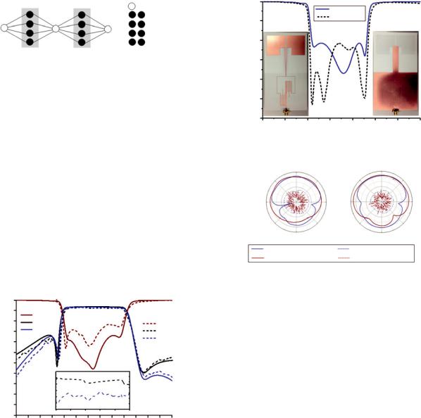
Wideband dipole antenna fed by balun BPF: Now, let’s employ this proposed balun BPF to feed a balanced dipole antenna with flat shape as shown in part 2 of Fig. 1, aiming to achieve wideband radiation performance and high selectivity out of the desired band of radiation. Two sectional microstrip lines are adopted herein to link the proposed balun BPF with the dipole antenna. The first section is a folded line with the length of about λ/2 utilised to transmit the balanced signal while keeping the 50-Ω output impedances of the balun BPF unchanged. The second one is a tapered line utilised to transform the 50-Ω output impedance in the 120-Ω input balanced impedance of the flat dipole antenna. The detailed geometrical parameters are listed in Fig. 1. The topand bottom-view photographs of the fabricated antenna are depicted in the leftand right-side insets. Simulated and measured reflection coefficients of the antenna are presented in Fig. 5, and they are found to agree well with each other. The designed antenna covers the operating band from 1.4 to 1.9 GHz or the FBW of about 30%, over which the reflection coefficient is less than −10 dB. The radiation patterns, including coand cross-polarisations, are measured in the two main planes, i.e. E-plane in the XY-plane and H-plane in the YZ-plane, as labelled in Fig. 1. Figs. 6a and b indicate the measured radiation patterns at 1.5 and 1.8 GHz, respectively. They are exhibited to behave like quasi-omnidirectional H-plane and ‘8-shape’ E-plane, similarly to those of an ideal dipole. The maximum radiation gain achieves 2.4 dBi in the band of interest.
0
|
|S11| simulated |
|
|S11| simulated |
|
–5 |
dB |
–10 |
|
|
parameters,-S |
–15 |
|
|
|
–20 |
|
–25 |
|
–30 |
1.0 |
1.2 |
1.4 |
1.6 |
1.8 |
2.0 |
2.2 |
2.4 |
|
|
|
frequency, GHz |
|
|
|
|
Fig. 5 Simulated and measured reflection coefficient of balun BPF integrated dipole antenna
315º |
–10 dB |
45º |
|
315º |
–10 dB |
45º |
|
|
|
|
|
||
|
–20 dB |
|
|
|
–20 dB |
|
270º |
|
|
90º |
270º |
|
90º |
225º |
|
135º |
|
225º |
|
135º |
1.5 GHz |
180º |
|
|
1.8 GHz |
180º |
|
co-polarisation at E-plane |
|
cross-polarisation at E-plane |
||||
co-polarisation at H-plane |
|
cross-polarisation at H-plane |
||||
Fig. 6 Measured radiation patterns of balun BPF integrated dipole antenna
Conclusion: In this Letter, a new wideband balun BPF adopting the quadruple mode resonator has been presented and it has been further integrated with a balanced fat dipole antenna for enhancement of frequency selectivity. Both simulated and measured results indicate that the proposed balun BPF exhibits good properties of wide operation band, high frequency selectivity, and excellent balanced performance. The predicted reflection coefficient and radiation patterns are well verified by testing a fabricated antenna fed by a balun BPF.
© The Institution of Engineering and Technology 2016 Submitted: 4 March 2016 E-first: 1 June 2016
doi: 10.1049/el.2016.0716
One or more of the Figures in this Letter are available in colour online.
Gang Zhang, Jianpeng Wang and Wen Wu (Ministerial Key Laboratory of JGMT, Nanjing University of Science and Technology, Nanjing 210094, People’s Republic of China)
E-mail: eejpwang@gmail.com
References
1Zhang, G.Q., Chen, J.X., Shi, J., Tang, H., Chu, H., and Bao, Z.H.: ‘Design of multilayer balun filter with independently controllable dual
passbands’, IEEE Microw. Wirel. Compon. Lett., 2015, 25, (1), pp. 10–12, doi: 10.1109/LMWC.2014.2363018
2Yeung, L.K., and Wu, K.: ‘A dual-band coupled-line balun filter’, IEEE Trans. Microw. Theory Tech., 2007, 55, (11), pp. 2406–2411, doi: 10.1109/TMTT.2007.907402
3Sun, S., and Menzel, W.: ‘Novel dual-mode balun bandpass filters using single cross-slotted patch resonator’, IEEE Microw. Wirel Compon. Lett., 2011, 21, (8), pp. 415–417, doi: 10.1109/LMWC.2011.2158535
4Chu, H., and Chen, J.X.: ‘Dual-band substrate integrated waveguide balun bandpass filter with high selectivity’, IEEE Microw. Wirel. Compon. Lett., 2014, 24, (6), pp. 379–381, doi: 10.1109/LMWC.2014. 2313474
5Cai, C., Wang, J., Zhu, L., and Wu, W.: ‘A new approach to design microstrip wideband balun bandpass filter’, IEEE Microw. Wirel. Compon. Lett., 2016, 26, (2), pp. 116–118, doi: 10.1109/LMWC.2016. 2516760
6Pozar, D.M.: ‘Microwave engineering’ (Wiley, New York, 2005, 3rd edn.)
ELECTRONICS LETTERS 23rd June 2016 Vol. 52 No. 13 pp. 1153–1155