

диафрагмированные волноводные фильтры / 7d13a3f9-af0d-4d2c-adeb-ac0eb15472d1
.pdfProceedings of Asia-Pacific Microwave Conference 2006
Leaky Wave Radiation from Left-Handed Transmission Lines Composed of a Cut-off Parallel-Plate Waveguide Loaded with Dielectric Resonators
Tetsuya Ueda1, 2, Anthony Lai1, Naobumi Michishita1, and Tatsuo Itoh1
1. Department of Electrical Engineering, University of California, Los Angeles, CA 90095, USA
Tel: +1-310-206-4820, Fax: +1-310-206-4819
2. Department of Electronics, Kyoto Institute of Technology, Kyoto 606-8585, Japan Tel: +81-75-724-7469, Fax: +81-75-724-7400, E-mail: ueda@kit.ac.jp
Abstract — Leaky wave radiation from a onedimensional left-handed transmission line is investigated that is composed of a cut-off parallel plate waveguide loaded with dielectric resonators (DR). The left-handedness is established by the combination of negative effective permittivity due to the cut-off TE parallel plate waveguide mode and negative effective permeability originating from the macroscopic behavior of DRs under the fundamental TE resonance. The DRs are placed near an aperture on the side wall of the parallel plates. The numerical simulation and the measurement of the radiation patterns verify the backward wave propagation along the proposed waveguide, and the promising characteristics for applications to leaky wave antennas.
Index Terms — Left-handed transmission lines, parallel-plate waveguides, leaky wave antennas.
I. INTRODUCTION
Left-handed (LH) metamaterials have been intensively investigated for applications to planar lens, near field imaging, antennas, and so forth [1], [2]. The LH metamaterials have negative effective permittivity and permeability simultaneously, and permit backward wave propagation. Most of such artificial materials are classified into two structures; one is the combination of split ring resonators (SRR) and thin wires, and the other is the transmission line loaded with series capacitive and shunt inductive elements. It is noted that they are both made of metals. However, metals are no longer a good conductor and can cause some serious insertion loss when they are used in resonant sections at higher frequencies, such as terahertz region and beyond.
Recently, some types of LH metamaterials have been proposed without metals by using dielectric resonators (DR). One is two-DR scheme, which is composed of both TE and TM resonances of DRs, the operation of which corresponds to split ring
resonators and thin wires, respectively [3], [4]. However, from the point of view of fabrication tolerance, it is difficult to adjust both TE and TM resonant frequencies of DRs because of their narrow operational bands. The other type is one-DR scheme [5]. It is constructed based on the mutual coupling between DRs. They can have a wide operational band due to the coupling between DRs. However, the operation is sensitive to the arrangements of lattice structures.
On the other hand, it is well-known that the effective dielectric constant of TE modes in metallic waveguides becomes negative at frequencies below the cut-off. A rectangular waveguide below the cutoff loaded with SRR has been proposed and demonstrated as a one-dimensional (1-D) LH transmission waveguide since the SRR shows negative effective permeability [6]. It is noted that the operation is very similar to conventional evanescent mode filters using DRs in rectangular waveguides [7], [8]. Recently, the authors proposed and demonstrated a two-dimensional (2-D) negative refraction in one-DR scheme in the cut-off background using a square lattice of DRs under the TE resonance that is inserted in a cut-off parallel plate waveguide [9]. Although the parallel plates are made of metal, the resonant structure is dielectric so that the metal loss is expected to be much smaller than the SRR type. Hence, the structure is suited at higher frequencies.
In this work, we investigate the leaky wave radiation from the 1-D left-handed transmission line that is composed of cut-off parallel-plate waveguide loaded with DRs under the TE resonance to confirm backward wave propagation of the leaky mode in the waveguide, and to open up the applications to leaky wave antennas.
Copyright 2006 IEICE
II. GEOMETRY OF THE STRUCTURE
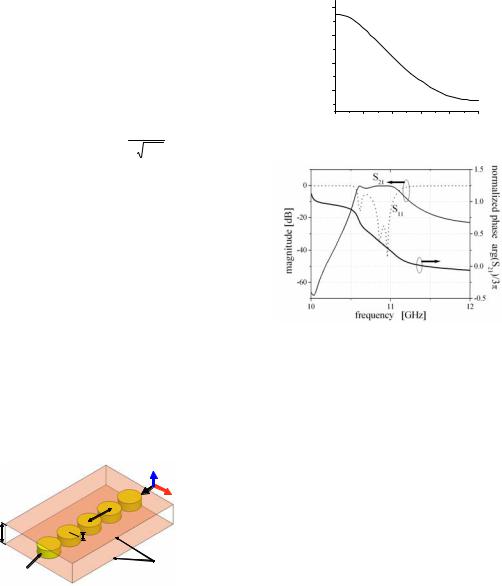
The geometry of the proposed 1-D LH transmission line is shown in Fig. 1. It is composed of a parallelplate waveguide loaded with disc type DRs. The TEn modes propagating along the parallel-plate waveguide without the dielectric resonators have the effective permittivity Heff,n in the following,
|
|
|
|
ª |
§Zc,n · |
2 º |
, |
Z |
|
|
nS c |
(1) |
||
H |
eff ,n |
H |
BG |
«1 |
¨ |
|
¸ |
» |
|
c,n |
|
|
|
|
|
|
|
|
|
||||||||||
|
|
« |
¨ |
Z |
¸ |
» |
|
|
d |
HBG |
|
|||
|
|
|
|
© |
¹ |
|
|
|
|
|||||
|
|
|
|
¬ |
|
|
|
¼ |
|
|
|
|
|
|
where Zc,n denotes the cut-off frequency of TEn mode, and d and HBG are the distance and dielectric constant of host medium between parallel plates, respectively. Therefore, the effective permittivity of the TEn modes becomes negative below the cut-off frequencies. In addition, fields of a fundamental TE01G resonant mode of disc type DRs behave like a magnetic dipole, so that their macroscopic behavior can gives negative effective permeability near and above the resonant frequency when the magnetic field component of the incident electromagnetic wave is parallel to the axis of the magnetic dipoles [10]. As seen from (1), the cut-off parallel-plate waveguide provides a wide stop band with a negative permittivity region. Therefore, it is easy to realize simultaneously negative permittivity and permeability even when the negative permeability is created by the TE resonance of the DRs.
|
H Incident wave |
|
E |
|
p |
d |
a |
|
h |
|
Parallel-plate waveguide |
|
Disc-type DR |
Fig. 1 Geometry of the problem.
III. DISPERSION DIAGRAM
In this section, we will numerically verify the lefthanded transmission characteristics of the proposed structure by showing the dispersion diagram for the case where the fields are well-confined inside the waveguide (Case without any radiation).
The various parameters used in the calculation are as follows; the dielectric constant, height, and radius of DRs are HDR = 38, h = 2.03 mm, and a = 2.55 mm, respectively. The parallel-pate waveguide is filled with a dielectric material with the dielectric constant of HBG = 2.2. The distance of the parallel plates d = 5mm and the length of the unit cell p = 6mm.
[GHz] |
11.2 |
|
|
|
|
|
11.0 |
|
|
|
|
|
|
|
|
|
|
|
|
|
frequency |
10.8 |
|
|
|
|
|
10.6 |
|
|
|
|
|
|
|
|
|
|
|
|
|
|
0.0 |
0.2 |
0.4 |
0.6 |
0.8 |
1.0 |
|
propagation constant |
E p / S |
||||
Fig. 2 Dispersion diagram for the proposed LHTL.
Fig. 3 Calculated transmission characteristics for 3-cell waveguide.
The obtained dispersion curve is shown in Fig. 2. It is noted that the cut-off frequency of TE1 parallelplate waveguide mode without DRs is estimated to be 20.2 GHz from (1), and that the resonant frequency of TE01G mode for a single dielectric resonator is numerically estimated to be 10.45 GHz for the isolated case where the DR is surrounded by the host medium with the dielectric constant of 2.2. As seen in Fig. 2, the backward wave mode is obtained above and near the resonant frequency of the TE01G DR mode but below the cut off frequency of the TE1 parallel-plate waveguide mode.
In addition to the dispersion diagram, the transmission characteristics for a finite unit cell structure are shown in Fig. 3. The number of the unit cells is three. The proposed parallel-plate waveguide is directly connected to the input and output terminals which are both composed of a 5mm x 5mm cross sectional rectangular waveguide filled with high dielectric material with the dielectric constant of 10.2 to operate above the cut-off. From the phase of S21 in the passband in Fig. 3, the backward wave characteristics are confirmed, since the phase at the output port gets advanced compared to that at the input port.
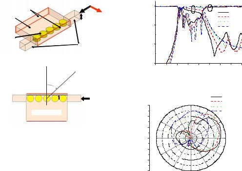
IV. WAVEGUIDE WITH APERTURES
A. Numerical simulation
open to the air |
TE10 mode |
||
E |
|||
host medium |
|
||
|
d = 5.00 mm |
||
HBG = 2.2 |
|
|
|
( fC = 20.2GHz) |
|
rectangular |
|
dielectric |
|
||
|
waveguide |
||
resonator |
|
||
|
Hr = 10.2 |
||
eDR = 38 |
|
||
Perspective view |
( fC = 9.4GHz) |
||
(a)
radiation
T
 s Input signal
RWG |
|
RWG |
Cut-off parallel plate
Fig. 4 Geometry of the LH transmission lines with apertures. (a) Perspective view. (b) Top view.
In this section, we consider the cut-off parallel plate waveguide including DRs that are placed near an aperture, that is, the side wall of the parallel plates. The configuration is shown in Fig. 4. The quantity s denotes the depth of DRs placed inside the waveguide measured from a surface of the side wall of the waveguide. When the depth s is small, the propagated wave mode is coupled to the TEM mode propagating in the air and becomes a leaky wave mode.
The simulated transmission characteristics of the 5-cell waveguide are shown in Fig. 5, as a function of the depth s. As the depth s gets smaller, the radiation loss becomes larger. Therefore, the insertion loss of the waveguide increases with the reduction in depth of DRs in the higher frequency region of the LH passband where the operation is within radiation region.
In Fig. 6, the calculated E-plane far-field radiation patterns are shown for the depth s = 1mm. As predicted, backward wave radiation is obtained at frequencies where the insertion loss is significant in the LH passband. From the figure, the radiation angle is estimated to be T = 64 deg, 48 deg, 41deg, at 10.7 GHz, 10.9 GHz, and 11.0 GHz, respectively. The numerical results verify the backward wave propagation along the proposed waveguide.
B. Experiments
Based on the numerical simulation, the cut-off parallel-plate waveguide loaded with DRs was fabricated, and the transmission and radiation characteristics were measured. RT/Duroid 5880 substrate with dielectric constant of 2.2 was used as a host medium between the parallel plates, and
|
0 |
|
S21 |
S11 |
|
|
|
|
|
|
|
|
|
|
|
|
d = 0.45 mm |
[dB] |
|
|
|
|
d = 1 mm |
-20 |
|
|
|
d = 2 mm |
|
|
|
|
d = 3 mm |
||
magnitude |
-40 |
|
|
|
|
|
|
|
|
|
|
|
-60 |
|
|
|
|
|
10.0 |
10.5 |
11.0 |
11.5 |
12.0 |
|
|
frequency [GHz] |
|
||
Fig. 5 Calculated transmission characteristics for 5- cell waveguide as a function of the depth of DRs.
|
|
|
f = 10.7 GHz |
10 |
0 |
|
f = 10.9 GHz |
330 |
30 |
f = 11.0 GHz |
|
|
|
|
f = 11.2 GHz |
0 |
300 |
|
60 |
|
|
||
-10 |
|
|
|
-20 |
270 |
|
90 |
-10 |
|
|
|
0 |
240 |
|
120 |
|
|
|
|
10 |
210 |
150 |
|
180 |
|
|
|
|
|
|
Fig. 6 Simulated E-plane radiation patterns from 5- cell LHTL for s = 1mm.
RT/Duroid 6010 substrate was chosen as a dielectric medium filling 30mm-long and 5mm x 5mm crosssectional rectangular waveguides for input and output ports. It should be mentioned that the 5mm x 5mm TE10 rectangular waveguide mode was excited and received with X-band rectangular waveguides, WR-90, at input and output ports, respectively.
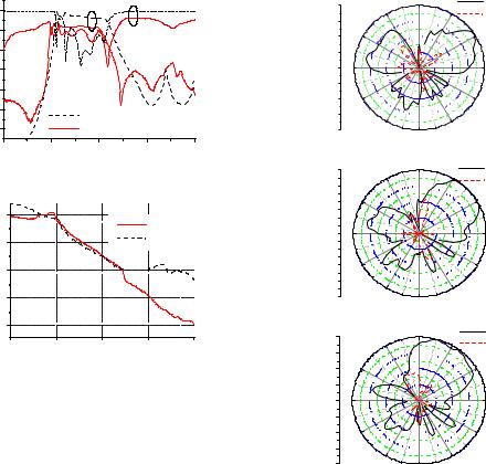
In Fig. 7, the measured transmission characteristics for the depth s = 1 mm are shown along with the numerical simulation for comparison. As seen in Fig. 7(a), the passband measured in the experiment appears from 10.5 GHz to 11.0 GHz, as predicted in the numerical simulation. But the measured insertion loss is more significant with the difference by 5dB. It is found from Fig. 7(b) that the measured phase characteristics are in a good agreement with the numerical results.
In Fig. 8, measured E-plane radiation patterns are shown together with cross-polarized radiation patterns. The cross-polarized radiation powers were less than -10 dB compared to the E-plane radiation. From the radiated patterns, backward wave radiation is confirmed with ș = 57 deg, 44 deg, and 39 deg at 10.7 GHz, 10.9 GHz, and 11.0 GHz, respectively. Therefore, the radiation measurements verify that the leaky mode propagating along the proposed waveguide is backward waves. In addition, the
|
|
|
|
|
S21 |
S11 |
|
|
|
|
|
|
0 |
|
|
0 |
E-plane |
||
|
|
|
0 |
|
|
|
|
|
|
|
|
330 |
30 |
||||||
|
|
|
|
|
|
|
|
|
|
|
cross |
||||||||
|
|
|
|
|
|
|
|
|
|
|
|
|
|
-5 |
|
|
|
||
|
|
-10 |
|
|
|
|
|
|
|
|
|
|
|
|
|
|
|||
|
[dB] |
|
|
|
|
|
|
|
|
|
|
-10 |
|
300 |
60 |
|
|||
|
|
|
|
|
|
|
|
|
|
|
|
|
|
|
|
|
|||
|
-20 |
|
|
|
|
|
|
|
|
|
|
-15 |
|
|
|
|
|||
|
magnitude |
-30 |
|
|
|
|
|
|
|
|
|
|
-20 |
|
270 |
|
9 0 |
||
|
-50 |
|
|
|
|
|
|
|
|
|
|
-15 |
|
|
|
|
|||
|
|
-40 |
|
|
|
|
|
|
|
|
|
|
-10 |
|
|
|
|
||
|
|
|
|
|
|
|
|
|
|
|
|
|
|
|
240 |
120 |
|||
|
|
-60 |
|
|
simulated |
|
|
|
|
|
|
-5 |
|
|
|
|
|||
|
|
|
|
measured |
|
|
|
|
|
|
0 |
|
210 |
150 |
|
||||
|
|
|
|
|
|
|
|
|
|
|
|
|
|
|
|
|
180 |
|
|
|
|
|
10.0 |
10.5 |
11.0 |
11.5 |
12.0 |
|
|
|
|
|
|
(a) |
|
||||
|
|
|
|
|
frequency |
[GHz] |
|
|
|
|
|
0 |
|
|
0 |
E-plane |
|||
|
|
|
|
|
|
(a) |
|
|
|
|
|
|
|
|
330 |
30 |
|||
|
|
|
|
|
|
|
|
|
|
|
|
|
-5 |
|
|
|
cross |
||
|
|
|
|
|
|
|
|
|
|
|
|
|
|
-10 |
|
300 |
60 |
|
|
|
|
|
|
|
|
|
|
|
|
|
|
|
|
|
|
|
|
||
|
|
|
1.0 |
|
|
|
|
measured |
|
|
|
|
-15 |
|
|
|
|
||
|
|
|
|
|
|
|
|
|
|
|
|
-20 |
|
270 |
|
90 |
|||
|
|
|
0.5 |
|
|
|
|
simulated |
|
|
|
|
|
|
|||||
|
|
|
|
|
|
|
|
|
|
|
-15 |
|
|
|
|
||||
|
S |
|
|
|
|
|
|
|
|
|
|
|
|
|
|
|
|||
|
|
|
|
|
|
|
|
|
|
|
|
|
|
|
|
|
|||
|
/ 5 |
|
0.0 |
|
|
|
|
|
|
|
|
|
|
-10 |
|
240 |
120 |
||
|
arg(S21) |
|
|
|
|
|
|
|
|
|
|
|
|
||||||
|
|
|
|
|
|
|
|
|
|
|
|
0 |
|
|
180 |
|
|||
|
|
-0.5 |
|
|
|
|
|
|
|
|
|
|
|
|
|
||||
|
|
|
|
|
|
|
|
|
|
|
|
|
|
-5 |
|
|
|
|
|
|
|
|
|
|
|
|
|
|
|
|
|
|
|
|
|
210 |
150 |
|
|
|
|
|
-1.0 |
|
|
|
|
|
|
|
|
|
|
|
|
|
(b) |
|
|
|
|
|
|
|
|
|
|
|
|
|
|
|
0 |
|
|
0 |
E-plane |
||
|
|
|
|
|
|
|
|
|
|
|
|
|
|
|
330 |
30 |
|||
|
|
|
10.0 |
|
10.5 |
11.0 |
11.5 |
12.0 |
|
|
|
|
cross |
||||||
|
|
|
|
|
|
|
-5 |
|
|
|
|||||||||
|
|
|
|
|
|
|
|
|
|
|
|||||||||
|
|
|
|
|
frequency |
[GHz] |
|
|
|
|
|
|
|
|
|
||||
|
|
|
|
|
|
|
|
|
|
-10 |
|
300 |
60 |
|
|||||
|
|
|
|
|
|
|
|
|
|
|
|
|
|
|
|
||||
Fig. |
7 |
|
Simulated |
and |
measured |
transmission |
|
|
|
|
|
|
|
||||||
|
|
|
|
-15 |
|
|
|
|
|||||||||||
characteristics |
for |
5-cell |
LHTL with s |
= 1 mm. (a) |
|
|
|
|
|
|
|
||||||||
|
|
|
-20 |
270 |
|
90 |
|||||||||||||
Magnitude of scattering parameters. (b) Phase of S21. |
|
|
|
|
|||||||||||||||
|
|
|
-15 |
|
|
|
|
||||||||||||
|
|
|
|
|
|
|
|
|
|
|
|
|
|
|
|
|
|
||
radiation angle approaches normal to the waveguide |
|
|
|
-10 |
|
240 |
120 |
||||||||||||
|
|
|
-5 |
|
|
|
|
||||||||||||
as the operational frequency increases. The result is |
|
|
|
0 |
|
210 |
150 |
|
|||||||||||
also in a good agreement with the numerical results |
|
|
|
|
|
|
180 |
|
|||||||||||
Fig. 8 Measured E-plane radiation patterns from 5-cell |
|||||||||||||||||||
in Fig. 6. It is noted that the significantly large lobes |
|||||||||||||||||||
LHTL with s = 1 mm along with cross polarization |
|||||||||||||||||||
are found at lower operational frequencies around at |
patterns. (a) f = 10.7 GHz. (b) f = 10.9 GHz. (c) f = 11.0 |
||||||||||||||||||
ș = 300 deg, although they are not found in the |
GHz |
|
|
|
|
|
|
||||||||||||
simulation. It may originate from the radiated wave |
Manufacturing Co. Ltd. for providing dielectric resonators. |
||||||||||||||||||
reflection from the obstacle rectangular waveguides, |
|||||||||||||||||||
|
|
|
|
|
|
|
|
||||||||||||
WR-90, that were used for terminals because of the |
|
|
|
|
|
|
|
|
|||||||||||
short LH waveguide section and its large radiation |
|
|
|
|
|
REFERENCES |
|
||||||||||||
angle. |
|
|
|
|
|
|
|
|
|
|
[1] V. G. Veselago, Sov. Phys. Usp., 10, 509, 1968. |
||||||||
|
|
|
|
|
|
|
|
|
|
|
|||||||||
|
|
|
|
|
|
|
|
|
|
|
[2] D. R. Smith, W. J. Padilla, D. C. Vier, S. C. Nemat- |
||||||||
|
|
|
|
VI. CONCLUSION |
|
|
|
|
|
Nasser, S. Schultz, Phys. Rev. Lett., 84, 4184, 2000. |
|||||||||
|
|
|
|
|
|
|
[3] C. L. Holloway, E. Kuester, J. Baker-Javis, P. Kabos, |
||||||||||||
|
|
|
|
|
|
|
|
|
|
|
|||||||||
Leaky wave radiation from a one-dimensional |
|
|
IEEE Trans. Antenna Propagation, 51, 2596, 2003. |
||||||||||||||||
[4] |
|
O. G. Vendik, M. S. Gashinova, |
Proc. of 34th |
||||||||||||||||
left-handed transmission line was investigated that |
|
|
European Microwave Conference, (Amsterdam, The |
||||||||||||||||
is composed of a cut-off parallel-plate waveguide |
|
|
|||||||||||||||||
|
|
Netherlands, 2004), 1209. |
|
||||||||||||||||
loaded with DRs. The numerical and experimental |
[5] E. A. Semouchkina, G. B. Semouchkin, M. Lanagan, |
||||||||||||||||||
radiation |
patterns |
verified |
the |
backward |
wave |
|
|
C. A. Randall, IEEE Trans. Microwave Theory Tech., |
|||||||||||
propagation along the proposed waveguide, and the |
|
|
53, |
1477, |
2005. |
|
|
||||||||||||
[6] |
|
R. Marques, J. Martel, F. Mesa, F. Medina, Phys. |
|||||||||||||||||
radiation |
characteristics |
promising |
for |
leaky |
wave |
|
|||||||||||||
antennas. |
|
|
|
|
|
|
|
|
|
|
Rev. Lett., 89, 183901, 2002. |
|
|||||||
|
|
|
|
|
|
|
|
[7] |
S. B. Cohn, IEEE Trans. Microwave Theory Tech., |
||||||||||
|
|
|
|
|
|
|
|
|
|
|
|
|
16, 218, 1968. |
|
|
||||
|
|
|
|
ACKNOWLEDGEMENT |
|
|
[8] Y. Konishi, Microwave Integrated Circuits, Dekker, |
||||||||||||
|
|
|
|
|
|
|
|
1991. |
|
|
|
|
|||||||
The authors would like to thank Dr. Kikuo Wakino, Dr. |
[9] T. Ueda, A. Lai, T. Itoh, to be presented in the 36th |
||||||||||||||||||
|
|
European Microwave Conference, EuMC23-4, 2006. |
|||||||||||||||||
Hiroshi |
Tamura, and Dr. Yukio Higuchi at |
Murata |
|
|
|||||||||||||||
[10] L. Lewin, Proc. Inst. Elec. Eng., 94, 65, 1947. |
|||||||||||||||||||
|
|
|
|
|
|
|
|
|
|
|
|||||||||