

59.3.1 Single current signalling
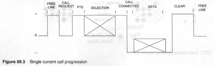
This describes a system using the presence or absence of current to indicate a start or stop polarity on the line. Usually the transmitter and receiver are connected in series to obtain the local record. The current source is led from the telex exchange to the machine, down Ihe telex line. The polarity of the current can change during signalling as well as being at an intermediate level. Single current operation normally works from a 120 volt exchange feed. (Figure 59.3)
59.3.2 Double current signalling
This describes a system using voltage/currents of equal magnitude hut opposite polarity, to indicate start or stop information on the line. The system generally has discrete send and receive paths with a common return and is inherently full duplex in operation. Mow-ever for normal telex use the local record is generated by linking the transmitter to the receive path in the machine and hence making this system effectively half duplex. Telex machines operate at the following voltages and currents at 20mA, 40mA, and 60mA Line currents for negative mark or positive space: (Figure 59.4)
80.0-80 Volts.
60-0-60 Volts.
48-0-48 Volts.
59.3.3 Single channel voice frequency signalling
Single channel voice frequency signalling (SCVF) was adopted by CCITT R 20 to improve the telex network for the following reasons:
To reduce the incidence of single or double current high level signals, inducing noise in adjacent cable pairs.
To reduce the power consumption of the telex exchange.
To enable connections to be made between telex machines over non metallic circuits.
To achieve full duplex transmission using relatively inexpensive CCITT V2I modems over 2 wire circuits.
The method of signalling is based on CCITT V21 with the following frequency allocations:
Telex exchange to telex machine, Space 0 = 1180 Hz; Mark 1= 980 Hz.
Telex machine to telex exchange, Space 0 = 1850 Hz; Mark I= 1650 Hz.

Figure 59.4 Double current call progression
59.3.4 Type a and Type b signalling
Two further subdivisions of the signalling systems have evolved, corresponding to the different types of national network employed. It has been agreed that, where two countries with different types of signalling system are trying to make connection, the country setting up the call will convert its outgoing signals to that of the country receiving the call. Both types of signals convey the same information, the difference is in the detail of implementation. In general Type A signalling has been used where the telex keyboard has been used lo send the address signals to the network and Type B signalling where the address signals were sent lo the network with dial pulses, much like a telephone. Figure 59.5 shows the sequence of signals in each system.
59.4 Answerback
CCITT recommendation F.60 specifies that every telex machine will have a unique answerback code made up of a one or two letter country code, telex line number and abbreviated subscriber's name. Sending a 'who are you' when connected through to the distant end will trigger the distant telex lo transmit the answerback aide embedded in the distant telex to the sending telex. This technique enables telex users to confirm that they have reached the correct distant party, before message transmission can begin, so protecting the confidentiality of the message.