

Figure 9 Comparisons of the k wave vectors given by the FDTD analysis with the k wave vectors obtained by the analytical plane-wave method. The FDTD analysis in the reciprocal space provides the propagative modes excited in the finite-size PBG structure
the structure. Moreover, this method is very easy to implement in an FDTD computational code.
REFERENCES
1.E. Yablonovitch and T.J. Gmitter, Photonic band structure: The face-centered-cubic case, J Opt Soc Amer A 7 1990..
2.D.R. Smith et al., Photonic band-gap structure and defects in one and two dimensions, J Opt Soc Amer B 10 1993..
3.A. Reinex and B. Jecko, A new photonic band gap equivalent model using finite difference time domain method, Ann Telecomun´ ´ 51 1996..
4.H.Y.D. Yang, Finite difference analysis of 2-D photonic crystals, IEEE Trans Microwave Theory Tech 44 1996..
5.M.M. Sigalas et al., Dipole antennas on photonic band-gap crystals}Experiment and simulation, Microwave Opt Technol Lett 15 1997..
6.J.G. Maloney, M.P. Kesler, B.L. Shirley, and G.S. Smith, A simple description for waveguiding in photonic bandgap materials, Microwave Opt Technol Lett 14 1997..
7.K.S. Yee, Numerical solution of initial boundary value problems involving Maxwell’s equations in isotropic media, IEEE Trans Antennas Propagat AP-14 1966., 302]307.
8.A. Taflove and M.E. Brodwin, Numerical solution of steady state electromagnetic scattering problems using the time-domain dependent Maxwell’s equations, IEEE Trans Microwave Theory Tech MTT-23 1975., 623]630.
Q 1999 John Wiley & Sons, Inc.
CCC 0895-2477r99
COMMUNITY GENETIC ALGORITHM DESIGN OF SYMMETRIC E-PLANE MICROWAVE FILTERS
Daniel S. Weile1 and Eric Michielssen1
1 Department of Electrical and Computer Engineering Center for Computational Electromagnetics University of Illinois at Urbana ] Champaign
Urbana, Illinois 61801
Recei¨ed 7 September 1998
ABSTRACT: The design of inducti¨e E-plane microwa¨e filters using a community genetic algorithm is discussed. The analysis of such de¨ices
necessary for their optimization is accomplished using an accurate equi¨- alent circuit technique that speeds the electromagnetic characterization of the filters, making stochastic optimization feasible. The community genetic algorithm is introduced as a two-tiered simple genetic algorithm. The stratified nature of this no¨el algorithm allows it to reuse redundant computations in the filter characterizations, speeding its con¨ergence compared to a simple genetic algorithm. Moreo¨er, the community structure of the algorithm is shown to enhance its robustness. The algorithm is applied to the design of bandpass filters with a prescribed maximum passband rejection, and numerical results are shown for a four-post and a six-post filter. Q 1999 John Wiley & Sons, Inc. Microwave Opt Technol Lett 21: 28]35, 1999.
Key words: microwa¨e filters; community genetic algorithm; E-plane filters
1. INTRODUCTION
Genetic algorithms GAs. have been applied extensively in the design of electromagnetic devices ranging from strip gratings to antenna arrays to microwave absorbers w1]3x. GAs are optimization techniques that mimic natural evolution, and that have attained popularity because they robustly locate global or strong local optima, operate without derivatives, and optimize functions of both discrete and continuous parameters. Moreover, unlike classical design and optimization techniques, GAs need no initial starting design, beginning instead with random designs and optimizing them. Despite all of these positive qualities, GAs typically require many more function evaluations than classical optimization schemes; as a result, their application to problems involving computationally intensive objective function evaluations is still in its infancy. This study, therefore, introduces a GA specifically designed for problems involving heavy computational loads and tailored to optimize in-line E-plane microwave filters.
In-line, inductive, E-plane microwave filters are used extensively in microwave circuits because they are easily mass produced and typically exhibit low losses w4]6x. Their salutary qualities with respect to construction derive from their simplicity: E-plane filters are generally composed of symmetrically placed inductive posts or fins situated inside a rectangular waveguide Fig. 1.. Because the band of operation of the filter generally precludes the existence of propagating waves in areas along the guide adjacent to the posts, these filters operate as a succession of cavities inductively coupled by the evanescent fields in the post regions.
This study introduces a community GA CGA. that retains the benefits of the simple GA SGA. w7x while accelerating its convergence. Based on a two-tiered SGA approach using an equivalent circuit model of the filter posts, the CGA will also be seen to improve GA robustness. Specifically, given a number of posts Np and waveguide width a, the CGA will optimize the length si and width ti for each post i s 1, . . . , Np, and the length li of the intervening guide cavity length. after each post i s 1, . . . , Np y 1 to achieve a desired bandpass filtering characteristic Fig. 1..
The rest of this paper is organized as follows. Section 2 describes the electromagnetic analysis of the filtering structure and the CGA itself. Section 3 demonstrates the CGA optimization process by presenting several numerical results. Finally, Section 4 relates the conclusions of this study.
2. FORMULATION
This section outlines the construction of the CGA for the optimization of microwave filters. Section 2.1 reviews the
28 MICROWAVE AND OPTICAL TECHNOLOGY LETTERS / Vol. 21, No. 1, April 5 1999

Figure 1 Two views of a two-post E-plane microwave filter, illustrating quantities relevant to its design
full-wave electromagnetic analysis of E-plane microwave filters and an equivalent circuit technique used by the CGA. The method used in this paper is due to Rozzi et al., and the discussion presented herein is essentially a summary of w4x. Section 2.2 then describes the CGA itself, with emphasis on its relationship to the problem at hand.
2.1. Analysis of E-Plane Microwa¨e Filters. Consider the construction of the na q 1. = na q 1. impedance Z. matrix of the single inductive post shown in Figure 2, detailing the interaction of the ‘‘accessible’’ TEn0 modes, n s 1, 3, . . . , na w4x. Because both the fields of the excitation and structure itself are symmetric with respect to x s ar2, a perfect magnetic conductor PMC. may be inserted there without altering the fields. Similarly, due to the symmetry of the post at the plane z s sr2, under oddreven excitation, the fields are unchanged by the insertion of a perfect electric conductorPEC.rPMC at z s sr2. Thus, the problem is reduced to finding the na q 1.r2 = na q 1.r2 impedance matrices Z e and Z o of a one-port step discontinuity terminated in a PMC and a PEC, respectively.
To analyze the step discontinuity, each mode in the both the guide to the left of the discontinuity z - 0. and the stub region 0 - z - sr2. can be described in terms of its z-di- rected electric field and admittance. The admittances are normalized so that the characteristic admittance of the fundamental guide mode is unity, resulting in the expressions
|
|
|
|
|
|
|
|
|
|
|
|
|
|
|
|
|
|
|
|
|
|
|
|
|
|
eXn x . s ( |
2 |
|
sin |
np x |
, |
|
|
||||||||||||||
¡yXo |
d |
|
|
d |
|
|
|||||||||||||||||
1 |
|
' |
|
|
|
|
|
|
|
|
|
|
|
|
|||||||||
n92 |
|
|
1 |
|
|
|
|
|
2 |
tanh gX s |
2, |
||||||||||||
|
|
|
|
|
|
|
|
v |
|||||||||||||||
|
|
|
|
|
|
|
|
|
|
||||||||||||||
|
n |
s |
|
|
|
|
|
|
y |
|
y |
|
|
|
|
|
|
|
n r |
|
|||
|
|
|
jv |
|
|
|
|
|
|
|
|
|
|
|
|
|
|
|
|
|
|||
ynX s~ for odd excitation |
|
|
|
|
|
|
|
|
1. |
||||||||||||||
|
Xe |
|
1 |
' |
|
|
|
|
|
|
|
|
|
|
|
|
|
||||||
|
|
|
92 |
|
|
|
|
|
|
2 |
|
|
gX |
|
|||||||||
|
|
|
|
|
|
|
v |
|
|
|
|||||||||||||
|
|
|
|
|
|
|
|
|
|
|
|
|
|
||||||||||
|
yn |
s j |
v |
|
|
n |
|
y 1 y |
|
|
|
|
|
coth |
n sr2, |
||||||||
¢ |
|
|
|
|
|
|
|
|
|
|
|
|
|||||||||||
for even excitation |
|
|
|
|
|
|
|
|
|
||||||||||||||
where the primes denote stub modes and admittances, d sa y t.r2, n9 s nard, and the normalized frequency v and
stub propagation constants |
gX |
are given by |
|
||||||||||||
|
|
|
|
|
|
|
n |
|
|
|
|
|
|
|
|
|
|
|
|
|
|
|
|
|
|
|
|
|
|
|
|
|
|
s ( |
ka |
2 |
|
|
|
p |
|
|
|
|
|
||
|
|
|
|
|
|
|
|
|
|
||||||
|
|
|
/ |
y 1 , gnX |
s |
|
'n92 y 1 y |
|
2 |
2. |
|||||
|
v |
v |
|||||||||||||
|
p |
a |
|||||||||||||
where k s v'm0 «0 is the free-space wavenumber of the exciting wave w4x. Assuming that the Z-matrix only includes interactions between the accessible modes and enforcing the continuity of tangential fields at the junction yields a set of integral equations w4x
em x . s Hd Y er o x N x9. Eme r o x9. dx9, |
m s 1, 3, . . . , na |
0 |
|
|
|
|
|
|
2 |
|
|
np x |
|
1 |
|
' |
|
|
|
|
|
3. |
||
|
|
|
. |
|
|
|
|
|
2 |
|
|
2 |
|
|||||||
|
|
|
|
|
|
|
|
|
v |
|
||||||||||
|
|
|
|
|
|
sin |
|
, yn s j |
|
|
y 1 y |
|
||||||||
en |
|
x |
|
s |
' |
a |
|
a |
|
n |
|
|
|
|
||||||
|
|
|
v |
|
|
where E er o |
x. is the unknown z-directed electric field in the |
|||||||||||||
|
|
|
|
|
|
|
|
|
|
|
|
|
|
|
|
|
|
|
n |
|
Figure 2 Cutaway top view of a single post
MICROWAVE AND OPTICAL TECHNOLOGY LETTERS / Vol. 21, No. 1, April 5 1999 |
29 |

junction due to a unit evenrodd of the nth mode and
`
Y er o x N x9. s yn en x . en x9.
nsn aq2 n odd
`
q yXne r oeXn x . eXn x9.. 4.
ns1
The notation n er o where n is any variable means that the same expression is valid for both even modes by replacing n er o with n e . and odd modes by replacing n er o with n o ..
Due to the edge condition at the post corner, the kernel of this integral vanishes as r 2r3 where r is the distance to the corner. To make the solution of 3. more efficient, its kernel can be made singular at the corner by integrating the equation with respect to x, and integrating by parts with respect to x9 w4x. This process yields a new set of integral equations
|
1 |
fm x . s Hd |
|
er o x N x |
|||||||
Y |
|||||||||||
|
|
|
|||||||||
|
m |
0 |
|
|
|
|
|
|
|||
where |
|
|
|
|
|
|
|
||||
|
|
|
|
|
` |
yn |
|||||
|
|
|
|
|
|
|
|
||||
Y er o x , x9. s |
|
|
|||||||||
|
|
n |
2 |
|
|||||||
|
|
|
|
|
nsn aq2 |
|
|
||||
|
|
|
|
|
|
|
|
||||
n odd
9. Eme r o x9. dx9,
m s 1, 3, . . . , na 5.
fn x .fn x9.
` |
ynXe r o |
||
q |
|
|
cn x .cnX x . |
n9 |
2 |
||
ns1 |
|
|
|
|
|
|
|
|
2 |
|
|
np x |
|
2 |
|
|
|
np x |
|
|
||||||
fn x . s |
|
|
|
cos |
|
, cn x . |
s ( |
|
|
cos |
|
|
|
, |
|
|
||
' |
|
|
a |
d |
|
|
d |
|
|
|||||||||
a |
|
|
|
|
||||||||||||||
|
|
|
|
|
|
|
|
|
|
|
|
a |
|
dE er o |
x . |
|||
|
|
|
|
|
|
Ener o x |
. s |
|
|
|
|
n |
|
. 6. |
||||
|
|
|
|
|
|
p |
|
|
dx |
|
||||||||
|
|
|
|
|
|
|
|
|
|
|
|
|
|
|
|
|||
The entry in the matrix Z er o |
relating the magnetic field of |
|||||||||||||||||
the TEm0 mode to the electric field of the TEk 0 mode, Zkemr o, m, k s 1, 3, . . . , na, can then be found formally. from w4x
Zkemr o s Hd ek x . Eme r o x . dx
0 |
|
|
|
|
|
s |
1 |
Hd fk x . ? |
|
e r o x N x9..y1 ? fm x9. dx. 7. |
|
Y |
|||||
km |
|||||
|
0 |
|
|
This equation must be discretized to find the Zkemr o numerically. This can be accomplished by projecting the functions of x and x9 onto a suitable basis. Because this procedure is not essential to the rest of the development, it is only noted that this procedure results in the approximation
|
Zke mr o s |
1 |
aTk Y e r o .y1a m |
|
|
|
8. |
||||||
|
km |
|
|
|
|||||||||
|
|
|
|
|
|
|
|
|
|
|
|
||
where the superscript ‘‘T ’’ denotes the transpose, |
|
|
|||||||||||
|
` |
y |
|
|
|
|
` |
|
yXe r o |
|
|
||
|
Ykemr o s |
|
n |
akn amn q |
|
n |
|
aXkn aXmn |
9. |
||||
|
|
2 |
|
n9 |
2 |
||||||||
|
nsn aq2 |
n |
|
ns1 |
|
|
|
|
|
||||
|
n odd |
|
|
|
|
|
|
|
|
|
|
|
|
and a k s wak1 ak 2 ??? xT, aXk s waXk1 |
aXk 2 ??? xT, where |
ak n |
and |
||||||||||
aX |
are the projections of |
f x. |
and |
c x. onto |
the |
kth |
|||||||
kn |
|
|
|
|
|
n |
|
|
n |
|
|
|
|
basis, respectively. Obviously, in practice, the vectors a k and a m and the matrix Y er o will need to be truncated at some
finite value Npoles , which will be seen to dictate the number of poles retained in the eventual circuit model. Generally,
retaining fewer than four poles results in a very accurate model, with an error of less than 0.1%. Once the elements of Z e and Z o, the impedance matrices of the step under even or odd excitation, are found using Eq. 8., the na q 1. = na q 1. impedance matrix of the post is given by
1 |
|
|
Z e q Z o |
Z e y Z o |
|
. |
10. |
|||||
|
|
|||||||||||
Z s |
|
|
|
e |
y Z |
o |
e |
q Z |
o |
|
||
|
|
|
||||||||||
2 |
|
|
Z |
|
Z |
|
|
|
|
|||
To arrive at an equivalent circuit, note that the only terms in 8.] 10. that depend on v are yn and yXne r o. Thus, these variables are approximated as lumped impedances:
jv yn v . f ynL y v 2 ynC , jv yXne r o v . f yXnL e r o y v 2 yXnC e r o .
11.
For n - 5, the constants ynL, ynC, yXnL e r o, and yXnC e r o can be found by minimizing the relative error in expansion 11.; for
n G 5, these values can be taken as the coefficients of the
Maclaurin |
series in |
the expansions |
of |
j |
v |
yn |
v |
. |
and |
||||||||||
j |
|
ynXe r o |
|
. with respect to the variable |
|
2 |
with very little |
||||||||||||
v |
v |
v |
|||||||||||||||||
error. |
|
|
|
|
|
|
|
|
|
|
|
|
|
|
|
||||
|
|
Due to the lossless nature of the post, Y er o can be written |
|||||||||||||||||
as jBer o |
where Be r o |
is purely real. Equations 11. |
then |
||||||||||||||||
imply that |
the matrix |
|
Ber o can be approximated in the |
||||||||||||||||
v |
|||||||||||||||||||
form |
|
|
|
|
|
|
|
|
|
|
|
|
|
|
|
||||
|
|
|
|
|
|
|
Ber o s Le r o y |
|
2 C e r o . |
|
|
|
|
|
12. |
||||
|
|
|
|
|
v |
v |
|
|
|
|
|
||||||||
The matrices Ler o and C er o are symmetric, and Ler o can be shown to be positive definite w4x. Thus, defining Ler o .1r2 as the matrix square root of Ler o, and writing
Le r o .y1r2C e r o Le r o .y1r2 s V e r oLe r o V e r o .T 13.
where the columns of V er o and diagonal elements of Ler o are the eigenvectors and eigenvalues of Le r o .y1r2 C er o Ler o .y1r2 , respectively, the elements of the impedance matrix can be written as
Ze r o s jv a V e r o .T Le r o .1r2.T I y v 2Le r o .y1 km km k
= V e r o .T Le r o .1r2.a m 14.
where I is the identity matrix. Because the matrix I y v 2L is diagonal, 14. has explicit frequency dependence. Using 14. to find Z er o, the full impedance matrix of the post can be calculated from 10..
Once the Z-matrices of the posts composing the filter are constructed, they may be converted to equivalent scattering representations using well-known techniques. The S-matrix of the entire filter can then be found from standard transmission line theory w8x. Because na F 5 for practical problems, once the post equivalent circuits are constructed, the response of the filter can be found very rapidly.
2.2. The Community Genetic Algorithm. Although the cost of analyzing an E-plane filter is dominated by the characterization of its posts, the location of the resonance is set primarily
30 MICROWAVE AND OPTICAL TECHNOLOGY LETTERS / Vol. 21, No. 1, April 5 1999
by the resonator lengths between posts. This asymmetry between the amount of computation dependent on the different sets of parameters and their importance in influencing the transfer function of the filter is exploited by the CGA.
As mentioned briefly in the Introduction, the CGA is a two-tiered simple GA SGA.. The SGA works by successively applying three genetic operators selection, crossover, and mutation. to a population of chromosomes, each of which is an encoded representation of a single design, and we refer the reader to the extensive literature on GAs for a description of the basics of the SGA w2, 3, 7, 9, 10x. While many different chromosome encodings are possible, most SGAsand the CGA presented here. use a binary coding to describe the design parameters that are to be optimized as outlined in w7x.
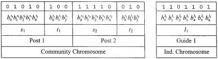
Unlike the SGA, however, the CGA population contains two different types of chromosomes, indi¨idual chromosomes and community chromosomes Fig. 3.. The description of a single microwave filter design with Np posts requires a community chromosome encoding the post parameters si and ti,
i s 1, . . . , Np, and an |
individual chromosome encoding the |
||
resonator parameters |
li, |
i s 1, . . . , Np y 1. If x is a |
given |
type of parameter i.e., |
x g s, t, l4., it is encoded using Nx |
||
bits, and can be decoded to yield real values between |
xmin |
||
and xmax using the |
standard decoding scheme shown in |
||
Figure 3 and described in w2, 3, 7x. |
|
||
The CGA begins with the random initialization of the |
|||
population Fig. 4.. A CGA population contains N c |
com- |
||
|
|
pop |
|
munity chromosomes, each of which is associated with a different community of Npopi individual chromosomes. In other words, the CGA population contains a total of Npop s Npopc = Npopi filter designs, organized in Npopc subpopulations or communities, and a unique post configuration characterizes each community. Each filter design k s 1, . . . , Npop is then analyzed using the technique of Section 2.1, and assigned a fitness value fki to be minimized. with the objective function
Npass
fki s max Rk vpass, j ., Rgoal . js1
Nstop
q max Tk vstop, j ., Tgoal . 15. js1
where vpass, j, j s 1, . . . , Npass are passband test frequencies, vstop, j , j s 1, . . . , Nstop are stopband test frequencies, Rk v.
and Tk v. are the reflection and transmission of the filter in
decibels., and Rgoal and Tgoal are the desired passband reflection and stopband transmission, respectively. As will be
outlined shortly, the CGA not only requires each individual to be evaluated, but also that communities as a whole are evaluated. If community l s 1, . . . , Npopc contains individuals
l y 1. Npopi q 1 through lNpopi , then it can be assigned an objective function value flc according to
flc s a min f ily1. Npoi pqk N k s 1, . . . , Npopi 4
|
1 y a . |
Npopi |
|
q |
f ily1. Npoi pqk 16. |
||
N i |
|||
|
pop |
ks1 |
where 0 F a F 1 dictates the relative importance of the best community member versus the community average in evaluating communities. As the optimization progresses, a should be increased to ensure that the best single design is found.
Once the individuals and communities are evaluated, the CGA operators are applied. While the SGA has three operators selection, crossover, and mutation., the CGA has six}selection, crossover, and mutation for both community and individual chromosomes. The algorithm operates in two distinct phases as highlighted in Figure 4: one in which community operators are applied, and another in which individual operators are applied. The community phase is discussed first.
The first operator applied during the community phase is community selection. Stochastic binary tournament selection is used; that is, two communities are chosen at random from the population, and their objective function values are compared. The community with the better objective function value is then placed in a new population. The process is repeated until this new population contains Npopc communities.
After community selection, the community crossover operator is applied. Two chromosomes are chosen at random from the population, and the community crossover operator is applied with probability pcc. If a given pair is to be crossed, a random point is chosen between two bits on the community chromosome. The community chromosomes swap all bits to the left of this crossover point to produce children, which are placed in a new population; the individual chromosomes associated with each community chromosome are unaffected by this operation Fig. 5.. Uncrossed pairs are simply copied into the new population. The process is repeated until, again, the new population contains Npopc communities.
Figure 3 Community chromosome and individual chromosome describing a single design, with two posts, and Ns s 5, Nt s 3, and
Nl s 6. If smin s 0.1 mm and smax s 1.0 mm, s1 decodes to 0.1 q 10 1.0 y 0.1.r31 s 0.3903 mm since the bits 01010 decode to 10 and the greatest integer encodable by 5 bits is 31 note that in a full CGA population, a community chromosome is associated with Npopi
individuals.
MICROWAVE AND OPTICAL TECHNOLOGY LETTERS / Vol. 21, No. 1, April 5 1999 |
31 |