

- •CONTENTS
- •FOREWORD
- •INTRODUCTION
- •SUMMARY OF CHANGES
- •100 GENERAL
- •102 DESIGN CRITERIA
- •103 CRITERIA FOR PRESSURE DESIGN OF PIPING COMPONENTS
- •104 PRESSURE DESIGN OF COMPONENTS
- •105 PIPE
- •106 FITTINGS, BENDS, AND INTERSECTIONS
- •107 VALVES
- •108 PIPE FLANGES, BLANKS, FLANGE FACINGS, GASKETS, AND BOLTING
- •110 PIPING JOINTS
- •111 WELDED JOINTS
- •112 FLANGED JOINTS
- •113 EXPANDED OR ROLLED JOINTS
- •114 THREADED JOINTS
- •115 FLARED, FLARELESS, AND COMPRESSION JOINTS, AND UNIONS
- •116 BELL END JOINTS
- •117 BRAZED AND SOLDERED JOINTS
- •118 SLEEVE COUPLED AND OTHER PROPRIETARY JOINTS
- •119 EXPANSION AND FLEXIBILITY
- •120 LOADS ON PIPE SUPPORTING ELEMENTS
- •121 DESIGN OF PIPE SUPPORTING ELEMENTS
- •122 DESIGN REQUIREMENTS PERTAINING TO SPECIFIC PIPING SYSTEMS
- •123 GENERAL REQUIREMENTS
- •124 LIMITATIONS ON MATERIALS
- •125 MATERIALS APPLIED TO MISCELLANEOUS PARTS
- •126 MATERIAL SPECIFICATIONS AND STANDARDS FOR STANDARD AND NONSTANDARD PIPING COMPONENTS
- •127 WELDING
- •128 BRAZING AND SOLDERING
- •129 BENDING AND FORMING
- •130 REQUIREMENTS FOR FABRICATING AND ATTACHING PIPE SUPPORTS
- •131 WELDING PREHEAT
- •132 POSTWELD HEAT TREATMENT
- •133 STAMPING
- •135 ASSEMBLY
- •136 INSPECTION AND EXAMINATION
- •137 PRESSURE TESTS
- •138 GENERAL
- •139 OPERATION AND MAINTENANCE PROCEDURES
- •140 CONDITION ASSESSMENT OF CPS
- •141 CPS RECORDS
- •Figures
- •Tables
- •102.4.3 Longitudinal Weld Joint Efficiency Factors
- •MANDATORY APPENDICES
- •Table A-4 Nickel and High Nickel Alloys
- •Chart D-1 Flexibility Factor, k, and Stress Intensification Factor, i
- •Chart D-2 Correction Factor, c
- •Fig. D-1 Branch Connection Dimensions
- •NONMANDATORY APPENDICES
- •INDEX
- •ASME B31.1 INTERPRETATIONS VOLUME 45
- •B31.1 — Cases No. 35

ASME B31.1-2010
Table A-4 Nickel and High Nickel Alloys
Maximum Allowable Stress Values in Tension, ksi, for Metal Temperature, °F, Not Exceeding |
|
|
−20 |
UNS |
|
to |
Alloy |
Spec. |
100 200 300 400 500 600 650 700 750 800 850 900 950 1,000 1,050 1,100 1,150 1,200 |
No. |
No. |
|
|
|
|
|
|
|
|
|
|
|
|
|
|
|
|
|
|
|
|
Seamless Pipe and Tube |
||
10.0 |
10.0 |
10.0 |
10.0 |
10.0 |
10.0 . . . . . . . . . . . . . . . . . . . . . |
. . . |
. . . |
. . . |
. . . |
. . . |
N02200 |
B 161 |
|||||||
8.0 |
8.0 |
8.0 |
8.0 |
8.0 |
8.0 . . . . . . . . . . . . . . . . . . . . . |
. . . |
. . . |
. . . |
. . . |
. . . |
N02200 |
|
|||||||
18.6 |
18.6 |
18.6 |
18.6 |
18.3 |
17.7 . . . . . . . . . . . . . . . . . . . . . |
. . . |
. . . |
. . . |
. . . |
. . . |
N02200 |
|
|||||||
8.0 |
7.7 |
7.5 |
7.5 |
7.5 |
7.5 |
7.5 |
7.4 |
7.4 |
7.2 |
5.8 |
4.5 |
3.7 |
3.0 |
2.4 |
2.0 |
1.5 |
1.2 |
N02201 |
B 161 |
6.7 |
6.4 |
6.3 |
6.2 |
6.2 |
6.2 |
6.2 |
6.2 |
6.1 |
6.0 |
5.8 |
4.5 |
3.7 |
3.0 |
2.4 |
2.0 |
1.5 |
1.2 |
N02201 |
|
17.1 |
17.1 |
17.0 |
17.0 |
16.8 |
16.3 . . . . . . . . . . . . . . . . . . . . . |
. . . |
. . . |
. . . |
. . . |
. . . |
N02201 |
|
|||||||
20.0 |
18.5 |
17.8 |
17.2 |
16.8 |
16.3 |
16.1 |
15.9 |
15.7 |
15.5 |
15.3 |
15.1 |
14.9 |
14.7 |
14.5 |
13.0 |
9.8 |
6.6 |
N08800 |
B 163 |
20.0 |
20.0 |
20.0 |
20.0 |
20.0 |
20.0 |
20.0 |
20.0 |
20.0 |
20.0 |
20.0 |
20.0 |
20.0 |
19.9 |
17.0 |
13.0 |
9.8 |
6.6 |
N08800 |
|
16.7 |
15.4 |
14.4 |
13.6 |
12.9 |
12.2 |
11.9 |
11.6 |
11.4 |
11.1 |
10.9 |
10.7 |
10.5 |
10.4 |
10.2 |
10.0 |
9.3 |
7.4 |
N08810 |
|
16.7 |
16.7 |
16.7 |
16.7 |
16.7 |
16.7 |
16.1 |
15.7 |
15.3 |
15.0 |
14.7 |
14.5 |
14.2 |
14.0 |
13.8 |
11.6 |
9.3 |
7.4 |
N08810 |
|
18.7 |
16.4 |
15.2 |
14.7 |
14.7 |
14.7 |
14.7 |
14.6 |
14.5 |
14.3 |
11.0 |
8.0 . . . |
. . . |
. . . |
. . . |
. . . |
. . . |
N04400 |
B 165 |
|
16.7 |
14.6 |
13.6 |
13.2 |
13.1 |
13.1 |
13.1 |
13.0 |
12.9 |
12.7 |
11.0 |
8.0 . . . |
. . . |
. . . |
. . . |
. . . |
. . . |
N04400 |
|
|
24.3 |
24.3 |
24.3 |
24.3 |
24.3 . . . . . . . . . . . . . . . . . . . . . . . . |
. . . |
. . . |
. . . |
. . . |
. . . |
N04400 |
|
||||||||
20.0 |
19.1 |
18.3 |
17.5 |
16.8 |
16.2 |
15.9 |
15.7 |
15.5 |
15.2 |
15.1 |
14.9 |
10.6 |
7.0 |
4.5 |
3.0 |
2.2 |
2.0 |
N06600 |
B 167 |
20.0 |
20.0 |
20.0 |
20.0 |
20.0 |
20.0 |
20.0 |
20.0 |
20.0 |
20.0 |
20.0 |
16.0 |
10.6 |
7.0 |
4.5 |
3.0 |
2.2 |
2.0 |
N06600 |
|
16.7 |
15.9 |
15.2 |
14.6 |
14.0 |
13.5 |
13.3 |
13.1 |
12.9 |
12.7 |
12.5 |
12.4 |
10.6 |
7.0 |
4.5 |
3.0 |
2.2 |
2.0 |
N06600 |
|
16.7 |
16.7 |
16.7 |
16.7 |
16.7 |
16.7 |
16.7 |
16.7 |
16.7 |
16.7 |
16.7 |
16.0 |
10.6 |
7.0 |
4.5 |
3.0 |
2.2 |
2.0 |
N06600 |
|
22.9 |
21.3 |
20.8 |
20.5 |
20.2 |
19.9 |
19.8 |
19.6 |
19.4 |
19.1 |
18.7 |
16.0 |
10.6 |
7.0 |
4.5 |
3.0 |
2.2 |
2.0 |
N06600 |
B 167 |
22.9 |
22.9 |
22.9 |
22.9 |
22.9 |
22.9 |
22.9 |
22.9 |
22.9 |
22.9 |
22.4 |
16.0 |
10.6 |
7.0 |
4.5 |
3.0 |
2.2 |
2.0 |
N06600 |
|
20.0 |
19.1 |
18.3 |
17.5 |
16.8 |
16.2 |
15.9 |
15.7 |
15.5 |
15.2 |
15.1 |
14.9 |
10.6 |
7.0 |
4.5 |
3.0 |
2.2 |
2.0 |
N06600 |
|
20.0 |
20.0 |
20.0 |
20.0 |
20.0 |
20.0 |
20.0 |
20.0 |
20.0 |
20.0 |
20.0 |
16.0 |
10.6 |
7.0 |
4.5 |
3.0 |
2.2 |
2.0 |
N06600 |
|
23.3 |
20.8 |
19.2 |
18.1 |
17.2 |
16.6 |
16.4 |
16.2 |
16.0 |
15.9 |
15.8 |
15.7 |
15.6 |
15.5 |
15.4 |
15.4 |
15.3 |
15.3 |
N06617 |
B 167 |
23.3 |
23.3 |
23.3 |
23.3 |
23.3 |
22.5 |
22.1 |
21.9 |
21.7 |
21.5 |
21.3 |
21.2 |
21.0 |
20.9 |
20.9 |
20.8 |
20.7 |
18.1 |
N06617 |
|
20.0 |
18.5 |
17.8 |
17.2 |
16.8 |
16.3 |
16.1 |
15.9 |
15.7 |
15.5 |
15.3 |
15.1 |
14.9 |
14.7 |
14.5 |
13.0 |
9.8 |
6.6 |
N08800 |
B 407 |
20.0 |
20.0 |
20.0 |
20.0 |
20.0 |
20.0 |
20.0 |
20.0 |
20.0 |
20.0 |
20.0 |
20.0 |
20.0 |
19.9 |
17.0 |
13.0 |
9.8 |
6.6 |
N08800 |
|
16.7 |
15.4 |
14.4 |
13.6 |
12.9 |
12.2 |
11.9 |
11.6 |
11.4 |
11.1 |
10.9 |
10.7 |
10.5 |
10.4 |
10.2 |
10.0 |
9.3 |
7.4 |
N08810 |
|
16.7 |
16.7 |
16.7 |
16.7 |
16.7 |
16.5 |
16.1 |
15.7 |
15.3 |
15.0 |
14.7 |
14.5 |
14.2 |
14.0 |
13.8 |
11.6 |
9.3 |
7.4 |
N08810 |
|
23.3 |
21.4 |
20.3 |
19.4 |
18.5 |
17.8 |
17.5 |
17.3 |
17.2 |
17.0 . . . . . . . . . |
. . . |
. . . |
. . . |
. . . |
. . . |
N08825 |
B 423 |
|||
23.3 |
23.3 |
23.3 |
23.3 |
23.3 |
23.3 |
23.3 |
23.3 |
23.2 |
23.0 . . . . . . . . . |
. . . |
. . . |
. . . |
. . . |
. . . |
N08825 |
|
|||
26.7 |
24.9 |
23.6 |
22.6 |
21.8 |
21.1 |
20.8 |
20.6 |
20.3 |
20.1 |
20.0 |
19.8 |
19.7 |
19.5 |
19.4 |
19.4 |
19.3 |
19.3 |
N06625 |
B 444 |
34.3 |
34.3 |
34.3 |
33.6 |
32.9 |
32.4 |
32.1 |
31.8 |
31.5 |
31.2 |
30.9 |
30.6 |
30.3 |
29.9 |
29.5 |
29.0 |
21.0 |
13.2 |
N06625 |
|
28.6 |
26.7 |
24.6 |
22.9 |
21.5 |
20.4 |
20.0 |
19.6 |
19.3 |
19.0 . . . . . . . . . |
. . . |
. . . |
. . . |
. . . |
. . . |
N06022 |
B 622 |
|||
28.6 |
28.6 |
28.2 |
27.2 |
26.5 |
26.0 |
25.8 |
25.6 |
25.4 |
25.3 . . . . . . . . . |
. . . |
. . . |
. . . |
. . . |
. . . |
N06022 |
|
|||
27.3 |
24.9 |
23.0 |
21.3 |
19.9 |
18.8 |
18.2 |
17.8 |
17.4 |
17.1 |
16.9 |
16.7 |
16.6 |
16.5 |
. . . |
. . . |
. . . |
. . . |
N10276 |
|
27.3 |
27.3 |
27.3 |
27.3 |
26.9 |
25.2 |
24.6 |
24.0 |
23.5 |
23.1 |
22.8 |
22.6 |
22.4 |
22.3 |
. . . |
. . . |
. . . |
. . . |
N10276 |
|
28.6 |
25.6 |
23.1 |
21.3 |
20.1 |
19.3 |
18.9 |
18.7 |
18.4 |
18.2 |
18.0 |
17.8 |
17.6 |
17.5 |
17.3 |
17.1 |
16.9 |
13.6 |
R30556 |
|
28.6 |
28.6 |
28.0 |
27.1 |
26.4 |
26.0 |
25.6 |
25.2 |
24.9 |
24.6 |
24.3 |
24.1 |
23.8 |
23.6 |
23.3 |
21.2 |
17.0 |
13.6 |
R30556 |
|
24.9 |
23.2 |
21.3 |
19.8 |
18.3 |
17.3 |
17.0 |
16.9 |
16.9 |
16.9 . . . . . . . . . |
. . . |
. . . |
. . . |
. . . |
. . . |
N08925 |
B 677 |
|||
24.9 |
24.9 |
23.9 |
23.0 |
22.1 |
21.4 |
21.1 |
20.8 |
20.4 |
20.1 . . . . . . . . . |
. . . |
. . . |
. . . |
. . . |
. . . |
N08925 |
|
|||
26.9 |
24.1 |
21.5 |
19.7 |
18.7 |
18.0 |
17.7 |
17.5 |
17.4 . . . . . . . . . . . . |
. . . |
. . . |
. . . |
. . . |
. . . |
N08926 |
|
||||
26.9 |
26.9 |
26.2 |
24.8 |
23.7 |
22.8 |
22.4 |
22.0 |
21.6 . . . . . . . . . . . . |
. . . |
. . . |
. . . |
. . . |
. . . |
N08926 |
|
||||
--`,,```````,,```,`,`,,,,`,`,`,`-`-`,,`,,`,`,,`---
165
Copyright ASME International
Provided by IHS under license with ASME
No reproduction or networking permitted without license from IHS

ASME B31.1-2010
Table A-4 Nickel and High Nickel Alloys (Cont’d)
|
|
|
|
|
|
Specified |
Specified |
|
|
UNS |
|
|
|
|
Minimum |
Minimum |
E |
Spec. |
Alloy |
Temper or |
Nominal |
P- |
|
Tensile, |
Yield, |
or |
No. |
No. |
Condition |
Composition |
No. |
Notes |
ksi |
ksi |
F |
|
|
|
|
|
|
|
||
Seamless Pipe and Tube (Cont’d) |
|
|
|
|
|
|
||
B 690 |
N08367 |
Sol. ann. |
Fe–Ni–Cr–Mo–Cu–N |
45 |
(1)(8)(22) |
95 |
45 |
1.00 |
|
N08367 |
Sol. ann. |
Fe–Ni–Cr–Mo–Cu–N |
45 |
(1)(2)(8)(22) |
95 |
45 |
1.00 |
|
N08367 |
Sol. ann. |
Fe–Ni–Cr–Mo–Cu–N |
45 |
(1)(21) |
100 |
45 |
1.00 |
|
N08367 |
Sol. ann. |
Fe–Ni–Cr–Mo–Cu–N |
45 |
(1)(2)(21) |
100 |
45 |
1.00 |
B 729 |
N08020 |
Annealed |
Ni–Fe–Cr–Mo–Cu–Cb |
45 |
(1) |
80 |
35 |
1.00 |
|
N08020 |
Annealed |
Ni–Fe–Cr–Mo–Cu–Cb |
45 |
(1)(2) |
80 |
35 |
1.00 |
Welded Pipe and Tube |
|
|
|
|
|
|
|
|
B 464 |
N08020 |
Annealed |
Ni–Fe–Cr–Mo–Cu–Cb |
45 |
(1) |
80 |
35 |
0.85 |
|
N08020 |
Annealed |
Ni–Fe–Cr–Mo–Cu–Cb |
45 |
(1)(2) |
80 |
35 |
0.85 |
B 468 |
N08020 |
Annealed |
Ni–Fe–Cr–Mo–Cu–Cb |
45 |
(1) |
80 |
35 |
0.85 |
|
N08020 |
Annealed |
Ni–Fe–Cr–Mo–Cu–Cb |
45 |
(1)(2) |
80 |
35 |
0.85 |
B 546 |
N06617 |
Annealed |
52Ni–22Cr–13Co–9Mo |
43 |
(1)(7) |
95 |
35 |
0.85 |
|
N06617 |
Annealed |
52Ni–22Cr–13Co–9Mo |
43 |
(1)(2)(7) |
95 |
35 |
0.85 |
B 619 |
N06022 |
Sol. ann. |
Ni–Mo–Cr–Low C |
44 |
(1)(12) |
100 |
45 |
0.85 |
|
N06022 |
Sol. ann. |
Ni–Mo–Cr–Low C |
44 |
(1)(2)(12) |
100 |
45 |
0.85 |
|
N10276 |
Sol. ann. |
Low C–Ni–Mo–Cr |
43 |
(1)(12) |
100 |
41 |
0.85 |
|
N10276 |
Sol. ann. |
Low C–Ni–Mo–Cr |
43 |
(1)(2)(12) |
100 |
41 |
0.85 |
|
R30556 |
Annealed |
Ni–Fe–Cr–Co–Mo–W |
45 |
(1) |
100 |
45 |
0.85 |
|
R30556 |
Annealed |
Ni–Fe–Cr–Co–Mo–W |
45 |
(1)(2) |
100 |
45 |
0.85 |
B 626 |
N06022 |
Sol. ann. |
Ni–Mo–Cr–Low C |
44 |
(1)(12) |
100 |
45 |
0.85 |
|
N06022 |
Sol. ann. |
Ni–Mo–Cr–Low C |
44 |
(1)(2)(12) |
100 |
45 |
0.85 |
|
N10276 |
Sol. ann. |
Low C–Ni–Mo–Cr |
43 |
(1)(12) |
100 |
41 |
0.85 |
|
N10276 |
Sol. ann. |
Low C–Ni–Mo–Cr |
43 |
(1)(2)(12) |
100 |
41 |
0.85 |
|
R30556 |
Annealed |
Ni–Fe–Cr–Co–Mo–W |
45 |
(1) |
100 |
45 |
0.85 |
|
R30556 |
Annealed |
Ni–Fe–Cr–Co–Mo–W |
45 |
(1)(2) |
100 |
45 |
0.85 |
B 673 |
N08925 |
Annealed |
Ni–Fe–Cr–Mo–Cu–Low C |
45 |
(1) |
87 |
43 |
0.85 |
|
N08925 |
Annealed |
Ni–Fe–Cr–Mo–Cu–Low C |
45 |
(1)(2) |
87 |
43 |
0.85 |
|
N08926 |
Annealed |
Ni–Fe–Cr–Mo–Cu–N–Low C |
45 |
(1)(19)(20) |
94 |
43 |
0.85 |
|
N08926 |
Annealed |
Ni–Fe–Cr–Mo–Cu–N–Low C |
45 |
(1)(2)(19)(20) |
94 |
43 |
0.85 |
B 674 |
N08925 |
Annealed |
Ni–Fe–Cr–Mo–Cu–Low C |
45 |
(1) |
87 |
43 |
0.85 |
|
N08925 |
Annealed |
Ni–Fe–Cr–Mo–Cu–Low C |
45 |
(1)(2) |
87 |
43 |
0.85 |
|
N08926 |
Annealed |
Ni–Fe–Cr–Mo–Cu–N–Low C |
45 |
(1)(19)(20) |
94 |
43 |
0.85 |
|
N08926 |
Annealed |
Ni–Fe–Cr–Mo–Cu–N–Low C |
45 |
(1)(2)(19)(20) |
94 |
43 |
0.85 |
B 675 |
N08367 |
Sol. ann. |
Fe–Ni–Cr–Mo–Cu–N |
45 |
(1)(8)(22) |
95 |
45 |
0.85 |
|
N08367 |
Sol. ann. |
Fe–Ni–Cr–Mo–Cu–N |
45 |
(1)(2)(8)(22) |
95 |
45 |
0.85 |
|
N08367 |
Sol. ann. |
Fe–Ni–Cr–Mo–Cu–N |
45 |
(1)(8)(21) |
100 |
45 |
0.85 |
|
N08367 |
Sol. ann. |
Fe–Ni–Cr–Mo–Cu–N |
45 |
(1)(2)(8)(21) |
100 |
45 |
0.85 |
B 676 |
N08367 |
Sol. ann. |
Fe–Ni–Cr–Mo–Cu–N |
45 |
(1)(8)(22) |
95 |
45 |
0.85 |
|
N08367 |
Sol. ann. |
Fe–Ni–Cr–Mo–Cu–N |
45 |
(1)(2)(8)(22) |
95 |
45 |
0.85 |
|
N08367 |
Sol. ann. |
Fe–Ni–Cr–Mo–Cu–N |
45 |
(1)(8)(21) |
100 |
45 |
0.85 |
|
N08367 |
Sol. ann. |
Fe–Ni–Cr–Mo–Cu–N |
45 |
(1)(2)(8)(21) |
100 |
45 |
0.85 |
166
--`,,```````,,```,`,`,,,,`,`,`,`-`-`,,`,,`,`,,`---
Copyright ASME International
Provided by IHS under license with ASME
No reproduction or networking permitted without license from IHS

ASME B31.1-2010
Table A-4 Nickel and High Nickel Alloys (Cont’d)
|
|
Maximum Allowable Stress Values in Tension, ksi, for Metal Temperature, °F, Not Exceeding |
|
|
|
||||||||||||||
−20 |
|
|
|
|
|
|
|
|
|
|
|
|
|
|
|
|
|
UNS |
|
to |
|
|
|
|
|
|
|
|
|
|
|
|
|
|
|
|
|
Alloy |
Spec. |
100 |
200 |
300 |
400 |
500 |
600 |
650 |
700 |
750 |
800 |
850 |
900 |
950 |
1,000 |
1,050 |
1,100 |
1,150 |
1,200 |
No. |
No. |
|
|
|
|
|
|
|
|
|
|
|
|
|
|
|
|
|
|||
|
|
|
|
|
|
|
|
|
|
|
|
|
|
|
|
Seamless Pipe and Tube (Cont’d) |
|||
27.1 |
26.2 |
23.8 |
21.9 |
20.5 |
19.4 |
19.0 |
18.6 |
18.3 |
18.0 . . . . . . . . . |
. . . |
. . . |
. . . |
. . . |
. . . |
N08367 |
B 690 |
|||
27.1 |
27.1 |
25.7 |
24.6 |
23.8 |
23.3 |
23.1 |
22.9 |
22.8 |
22.6 . . . . . . . . . |
. . . |
. . . |
. . . |
. . . |
. . . |
N08367 |
|
|||
28.6 |
26.2 |
23.8 |
21.9 |
20.5 |
19.4 |
19.0 |
18.6 |
18.3 |
18.0 . . . . . . . . . |
. . . |
. . . |
. . . |
. . . |
. . . |
N08367 |
|
|||
28.6 |
28.6 |
27.0 |
25.8 |
25.0 |
24.5 |
24.3 |
24.1 |
24.0 |
23.8 . . . . . . . . . |
. . . |
. . . |
. . . |
. . . |
. . . |
N08367 |
|
|||
22.9 |
20.6 |
19.7 |
18.9 |
18.2 |
17.7 |
17.5 |
17.4 |
17.2 |
16.8 . . . . . . . . . |
. . . |
. . . |
. . . |
. . . |
. . . |
N08020 |
B 729 |
|||
22.9 |
22.9 |
22.6 |
22.2 |
22.1 |
22.1 |
22.0 |
21.9 |
21.8 |
21.8 . . . . . . . . . |
. . . |
. . . |
. . . |
. . . |
. . . |
N08020 |
|
|||
|
|
|
|
|
|
|
|
|
|
|
|
|
|
|
|
|
Welded Pipe and Tube |
||
19.4 |
17.5 |
16.7 |
16.1 |
15.5 |
15.0 |
14.9 |
14.8 |
14.6 |
14.3 . . . . . . . . . |
. . . |
. . . |
. . . |
. . . |
. . . |
N08020 |
B 464 |
|||
19.4 |
19.4 |
19.2 |
18.8 |
18.8 |
18.8 |
18.7 |
18.6 |
18.5 |
18.5 . . . . . . . . . |
. . . |
. . . |
. . . |
. . . |
. . . |
N08020 |
|
|||
19.4 |
17.5 |
16.7 |
16.1 |
15.5 |
15.0 |
14.9 |
14.8 |
14.6 |
14.3 . . . . . . . . . |
. . . |
. . . |
. . . |
. . . |
. . . |
N08020 |
B 468 |
|||
19.4 |
19.4 |
19.2 |
18.8 |
18.8 |
18.8 |
18.7 |
18.6 |
18.5 |
18.5 . . . . . . . . . |
. . . |
. . . |
. . . |
. . . |
. . . |
N08020 |
|
|||
19.8 |
17.7 |
16.3 |
15.4 |
14.6 |
14.1 |
13.9 |
13.8 |
13.6 |
13.5 |
13.4 |
13.3 |
13.3 |
13.2 |
13.1 |
13.1 |
13.0 |
13.0 |
N06617 |
B 546 |
19.8 |
19.8 |
19.8 |
19.8 |
19.8 |
19.1 |
18.8 |
18.6 |
18.4 |
18.3 |
18.1 |
18.0 |
17.9 |
17.8 |
17.8 |
17.7 |
17.6 |
15.4 |
N06617 |
|
24.3 |
22.7 |
20.9 |
19.4 |
18.3 |
17.4 |
17.0 |
16.7 |
16.4 |
16.2 . . . . . . . . . |
. . . |
. . . |
. . . |
. . . |
. . . |
N06022 |
B 619 |
|||
24.3 |
22.7 |
20.9 |
19.4 |
18.3 |
17.4 |
17.0 |
16.7 |
16.4 |
16.2 . . . . . . . . . |
. . . |
. . . |
. . . |
. . . |
. . . |
N06022 |
|
|||
23.2 |
21.2 |
19.6 |
18.1 |
16.9 |
16.0 |
15.5 |
15.1 |
14.8 |
14.5 |
14.4 |
14.2 |
14.1 |
14.0 |
. . . |
. . . |
. . . |
. . . |
N10276 |
|
23.2 |
23.2 |
23.2 |
23.2 |
22.9 |
21.4 |
20.9 |
20.4 |
20.0 |
19.6 |
19.4 |
19.2 |
19.0 |
19.0 |
. . . |
. . . |
. . . |
. . . |
N10276 |
|
24.3 |
21.8 |
19.6 |
18.1 |
17.1 |
16.4 |
16.1 |
15.9 |
15.7 |
15.5 |
15.3 |
15.2 |
15.0 |
14.8 |
14.7 |
14.5 |
14.4 |
11.6 |
R30556 |
|
24.3 |
24.3 |
23.8 |
23.0 |
22.5 |
22.1 |
21.7 |
21.4 |
21.1 |
20.9 |
20.7 |
20.5 |
20.2 |
20.0 |
19.8 |
18.0 |
14.4 |
11.6 |
R30556 |
|
24.3 |
24.3 |
23.9 |
23.1 |
22.6 |
22.1 |
21.9 |
21.8 |
21.6 |
21.5 . . . . . . . . . |
. . . |
. . . |
. . . |
. . . |
. . . |
N06022 |
B 626 |
|||
24.3 |
24.3 |
23.9 |
23.1 |
22.6 |
22.1 |
21.9 |
21.8 |
21.6 |
21.5 . . . . . . . . . |
. . . |
. . . |
. . . |
. . . |
. . . |
N06022 |
|
|||
23.2 |
21.2 |
19.6 |
18.1 |
16.9 |
16.0 |
15.5 |
15.1 |
14.8 |
14.5 |
14.4 |
14.2 |
14.1 |
14.0 |
. . . |
. . . |
. . . |
. . . |
N10276 |
|
23.2 |
23.2 |
23.2 |
23.2 |
22.9 |
21.4 |
20.9 |
20.4 |
20.0 |
19.6 |
19.4 |
19.2 |
19.0 |
19.0 |
. . . |
. . . |
. . . |
. . . |
N10276 |
|
24.3 |
21.8 |
19.6 |
18.1 |
17.1 |
16.4 |
16.1 |
15.9 |
15.7 |
15.5 |
15.3 |
15.2 |
15.0 |
14.8 |
14.7 |
14.5 |
14.4 |
11.6 |
R30556 |
|
24.3 |
24.3 |
23.8 |
23.0 |
22.5 |
22.1 |
21.7 |
21.4 |
21.1 |
20.9 |
20.7 |
20.5 |
20.2 |
20.0 |
19.8 |
18.0 |
14.4 |
11.6 |
R30556 |
|
21.1 |
19.7 |
18.1 |
16.8 |
15.6 |
14.7 |
14.4 |
14.4 |
14.4 |
14.4 . . . . . . . . . |
. . . |
. . . |
. . . |
. . . |
. . . |
N08925 |
B 673 |
|||
21.1 |
21.1 |
20.4 |
19.5 |
18.8 |
18.2 |
17.9 |
17.7 |
17.4 |
17.0 . . . . . . . . . |
. . . |
. . . |
. . . |
. . . |
. . . |
N08925 |
|
|||
22.9 |
20.5 |
18.3 |
16.7 |
15.9 |
15.3 |
15.0 |
14.9 |
14.8 . . . . . . . . . . . . |
. . . |
. . . |
. . . |
. . . |
. . . |
N08926 |
|
||||
22.9 |
22.9 |
22.3 |
21.1 |
20.1 |
19.4 |
19.0 |
18.7 |
18.4 . . . . . . . . . . . . |
. . . |
. . . |
. . . |
. . . |
. . . |
N08926 |
|
||||
21.1 |
19.7 |
18.1 |
16.8 |
15.6 |
14.7 |
14.4 |
14.4 |
14.4 |
14.4 . . . . . . . . . |
. . . |
. . . |
. . . |
. . . |
. . . |
N08925 |
B 674 |
|||
21.1 |
21.1 |
20.4 |
19.5 |
18.8 |
18.2 |
17.9 |
17.7 |
17.4 |
17.0 . . . . . . . . . |
. . . |
. . . |
. . . |
. . . |
. . . |
N08925 |
|
|||
22.9 |
20.5 |
18.3 |
16.7 |
15.9 |
15.3 |
15.0 |
14.9 |
14.8 . . . . . . . . . . . . |
. . . |
. . . |
. . . |
. . . |
. . . |
N08926 |
|
||||
22.9 |
22.9 |
22.3 |
21.1 |
20.1 |
19.4 |
19.0 |
18.7 |
18.4 . . . . . . . . . . . . |
. . . |
. . . |
. . . |
. . . |
. . . |
N08926 |
|
||||
23.1 |
22.2 |
20.2 |
18.7 |
17.4 |
16.5 |
16.1 |
15.8 |
15.5 |
15.3 . . . . . . . . . |
. . . |
. . . |
. . . |
. . . |
. . . |
N08367 |
B 675 |
|||
23.1 |
23.1 |
21.8 |
20.9 |
20.2 |
19.8 |
19.6 |
19.5 |
19.4 |
19.2 . . . . . . . . . |
. . . |
. . . |
. . . |
. . . |
. . . |
N08367 |
|
|||
24.3 |
22.2 |
20.2 |
18.7 |
17.4 |
16.5 |
16.1 |
15.8 |
15.5 |
15.3 . . . . . . . . . |
. . . |
. . . |
. . . |
. . . |
. . . |
N08367 |
|
|||
24.3 |
24.3 |
23.0 |
22.0 |
21.3 |
20.8 |
20.7 |
20.5 |
20.4 |
20.2 . . . . . . . . . |
. . . |
. . . |
. . . |
. . . |
. . . |
N08367 |
|
|||
23.1 |
22.2 |
20.2 |
18.7 |
17.4 |
16.5 |
16.1 |
15.8 |
15.5 |
15.3 . . . . . . . . . |
. . . |
. . . |
. . . |
. . . |
. . . |
N08367 |
B 676 |
|||
23.1 |
23.1 |
21.8 |
20.9 |
20.2 |
19.8 |
19.6 |
19.5 |
19.4 |
19.2 . . . . . . . . . |
. . . |
. . . |
. . . |
. . . |
. . . |
N08367 |
|
|||
24.3 |
22.2 |
20.2 |
18.7 |
17.4 |
16.5 |
16.1 |
15.8 |
15.5 |
15.3 . . . . . . . . . |
. . . |
. . . |
. . . |
. . . |
. . . |
N08367 |
|
|||
24.3 |
24.3 |
23.0 |
22.0 |
21.3 |
20.8 |
20.7 |
20.5 |
20.4 |
20.2 . . . . . . . . . |
. . . |
. . . |
. . . |
. . . |
. . . |
N08367 |
|
|||
167 |
--`,,```````,,```,`,`,,,,`,`,`,`-`-`,,`,,`,`,,`--- |
|
Copyright ASME International
Provided by IHS under license with ASME
No reproduction or networking permitted without license from IHS

ASME B31.1-2010
Table A-4 Nickel and High Nickel Alloys (Cont’d)
|
|
|
|
|
|
Specified |
Specified |
|
|
UNS |
|
|
|
|
Minimum |
Minimum |
E |
Spec. |
Alloy |
Temper or |
Nominal |
P- |
|
Tensile, |
Yield, |
or |
No. |
No. |
Condition |
Composition |
No. |
Notes |
ksi |
ksi |
F |
|
|
|
|
|
|
|
||
Welded Pipe and Tube (Cont’d) |
|
|
|
|
|
|
||
B 704 |
N06625 |
Annealed |
Ni–Cr–Mo–Cb |
43 |
(1)(14) |
120 |
60 |
0.85 |
B 705 |
N06625 |
Annealed |
Ni–Cr–Mo–Cb |
43 |
(1)(14) |
120 |
60 |
0.85 |
B 804 |
N08367 |
Sol. ann. |
Fe–Ni–Cr–Mo–Cu–N |
45 |
(1)(8) |
95 |
45 |
0.85 |
|
N08367 |
Sol. ann. |
Fe–Ni–Cr–Mo–Cu–N |
45 |
(1)(2)(8) |
95 |
45 |
0.85 |
|
N08367 |
Sol. ann. |
Fe–Ni–Cr–Mo–Cu–N |
45 |
(1)(8)(21) |
100 |
45 |
0.85 |
|
N08367 |
Sol. ann. |
Fe–Ni–Cr–Mo–Cu–N |
45 |
(1)(2)(8)(21) |
100 |
45 |
0.85 |
Plate, Sheet, and Strip |
|
|
|
|
|
|
|
|
B 168 |
N06600 |
Annealed |
Ni–Cr–Fe |
43 |
(1) |
80 |
35 |
1.00 |
|
N06600 |
Annealed |
Ni–Cr–Fe |
43 |
(1)(2) |
80 |
35 |
1.00 |
|
N06600 |
Hot rolled |
Ni–Cr–Fe |
43 |
(1)(4) |
85 |
35 |
1.00 |
|
N06600 |
Hot rolled |
Ni–Cr–Fe |
43 |
(1)(2)(4) |
85 |
35 |
1.00 |
B 168 |
N06617 |
Annealed |
52Ni–22Cr–13Co–9Mo |
43 |
(1)(7) |
95 |
35 |
1.00 |
|
N06617 |
Annealed |
52Ni–22Cr–13Co–9Mo |
43 |
(1)(2)(7) |
95 |
35 |
1.00 |
B 409 |
N08800 |
Annealed |
Ni–Cr–Fe |
45 |
(4)(7) |
75 |
30 |
1.00 |
|
N08800 |
Annealed |
Ni–Cr–Fe |
45 |
(2)(4)(7) |
75 |
30 |
1.00 |
|
N08810 |
Annealed |
Ni–Cr–Fe |
45 |
(4)(7) |
65 |
25 |
1.00 |
|
N08810 |
Annealed |
Ni–Cr–Fe |
45 |
(2)(4)(7) |
65 |
25 |
1.00 |
B 424 |
N08825 |
Annealed |
Ni–Fe–Cr–Mo–Cu |
45 |
(1)(7) |
85 |
35 |
1.00 |
|
N08825 |
Annealed |
Ni–Fe–Cr–Mo–Cu |
45 |
(1)(2)(7) |
85 |
35 |
1.00 |
B 435 |
R30556 |
Annealed |
Ni–Fe–Cr–Co–Mo–W |
45 |
(1) |
100 |
45 |
1.00 |
|
R30556 |
Annealed |
Ni–Fe–Cr–Co–Mo–W |
45 |
(1)(2) |
100 |
45 |
1.00 |
B 443 |
N06625 |
Sol. ann. |
Ni–Cr–Mo–Cb |
43 |
(1)(14)(18) |
100 |
40 |
1.00 |
|
N06625 |
Annealed |
Ni–Cr–Mo–Cb |
43 |
(1)(14) |
110 |
55 |
1.00 |
|
N06625 |
Annealed |
Ni–Cr–Mo–Cb |
43 |
(1)(14)(15) |
120 |
60 |
1.00 |
B 463 |
N08020 |
Annealed |
Ni–Fe–Cr–Mo–Cu–Cb |
45 |
(1) |
80 |
35 |
1.00 |
|
N08020 |
Annealed |
Ni–Fe–Cr–Mo–Cu–Cb |
45 |
(1)(12) |
80 |
35 |
1.00 |
B 575 |
N06022 |
Sol. ann. |
Ni–Mo–Cr–Low C |
44 |
(1)(12) |
100 |
45 |
1.00 |
|
N06022 |
Sol. ann. |
Ni–Mo–Cr–Low C |
44 |
(1)(2)(12) |
100 |
45 |
1.00 |
|
N10276 |
Sol. ann. |
Low C–Ni–Mo–Cr |
43 |
(1)(12) |
100 |
41 |
1.00 |
|
N10276 |
Sol. ann. |
Low C–Ni–Mo–Cr |
43 |
(1)(2)(12) |
100 |
41 |
1.00 |
B 625 |
N08925 |
Annealed |
Ni–Fe–Cr–Mo–Cu–Low C |
45 |
(1) |
87 |
43 |
1.00 |
|
N08925 |
Annealed |
Ni–Fe–Cr–Mo–Cu–Low C |
45 |
(1)(2) |
87 |
43 |
1.00 |
|
N08926 |
Annealed |
Ni–Fe–Cr–Mo–Cu–N–Low C |
45 |
(1)(19)(20) |
94 |
43 |
1.00 |
|
N08926 |
Annealed |
Ni–Fe–Cr–Mo–Cu–N–Low C |
45 |
(1)(2)(19)(20) |
94 |
43 |
1.00 |
B 688 |
N08367 |
Sol. ann. |
Fe–Ni–Cr–Mo–Cu–N |
45 |
(1)(7)(11)(22) |
95 |
45 |
1.00 |
|
N08367 |
Sol. ann. |
Fe–Ni–Cr–Mo–Cu–N |
45 |
(1)(2)(7)(11)(22) |
95 |
45 |
1.00 |
|
N08367 |
Sol. ann. |
Fe–Ni–Cr–Mo–Cu–N |
45 |
(1)(7)(10)(21) |
100 |
45 |
1.00 |
|
N08367 |
Sol. ann. |
Fe–Ni–Cr–Mo–Cu–N |
45 |
(1)(2)(7)(10)(21) |
100 |
45 |
1.00 |
168
--`,,```````,,```,`,`,,,,`,`,`,`-`-`,,`,,`,`,,`---
Copyright ASME International
Provided by IHS under license with ASME
No reproduction or networking permitted without license from IHS
---`,,`,,`,`,,`-`-`,,```````,,```,`,`,,,,`,`,`,`--
ASME B31.1-2010
Table A-4 Nickel and High Nickel Alloys (Cont’d)
|
|
Maximum Allowable Stress Values in Tension, ksi, for Metal Temperature, °F, Not Exceeding |
|
|
|
|
|||||||||||||
−20 |
|
|
|
|
|
|
|
|
|
|
|
|
|
|
|
|
|
UNS |
|
to |
|
|
|
|
|
|
|
|
|
|
|
|
|
|
|
|
|
Alloy |
Spec. |
100 |
200 |
300 |
400 |
500 |
600 |
650 |
700 |
750 |
800 |
850 |
900 |
950 |
1,000 |
1,050 |
1,100 |
1,150 |
1,200 |
No. |
No. |
|
|
|
|
|
|
|
|
|
|
|
|
|
|
|
|
|
|||
|
|
|
|
|
|
|
|
|
|
|
|
|
|
|
|
Welded Pipe and Tube (Cont’d) |
|||
29.1 |
29.1 |
29.1 |
28.5 |
28.0 |
27.5 |
27.3 |
27.0 |
26.8 |
26.5 |
26.3 |
26.0 |
25.7 |
25.4 |
25.1 |
24.7 |
17.9 |
11.2 |
N06625 |
B 704 |
29.1 |
29.1 |
29.1 |
28.5 |
28.0 |
27.5 |
27.3 |
27.0 |
26.8 |
26.5 |
26.3 |
26.0 |
25.7 |
25.4 |
25.1 |
24.7 |
17.9 |
11.2 |
N06625 |
B 705 |
23.1 |
22.2 |
20.2 |
18.7 |
17.4 |
16.5 |
16.1 |
15.8 |
15.5 |
15.3 . . . . . . . . . |
. . . |
. . . |
. . . |
. . . |
. . . |
N08367 |
B 804 |
|||
23.1 |
23.1 |
21.8 |
20.9 |
20.2 |
19.8 |
19.6 |
19.5 |
19.4 |
19.2 . . . . . . . . . |
. . . |
. . . |
. . . |
. . . |
. . . |
N08367 |
|
|||
24.3 |
22.2 |
20.2 |
18.7 |
17.4 |
16.5 |
16.1 |
15.8 |
15.5 |
15.3 . . . . . . . . . |
. . . |
. . . |
. . . |
. . . |
. . . |
N08367 |
|
|||
24.3 |
24.3 |
23.0 |
22.0 |
21.3 |
20.8 |
20.7 |
20.5 |
20.4 |
20.2 . . . . . . . . . |
. . . |
. . . |
. . . |
. . . |
. . . |
N08367 |
|
|||
|
|
|
|
|
|
|
|
|
|
|
|
|
|
|
|
|
Plate, Sheet, and Strip |
||
22.9 |
21.3 |
20.8 |
20.5 |
20.2 |
19.9 |
19.8 |
19.6 |
19.4 |
19.1 |
18.7 |
16.0 |
10.6 |
7.0 |
4.5 |
3.0 |
2.2 |
2.0 |
N06600 |
B 168 |
22.9 |
22.9 |
22.9 |
22.9 |
22.9 |
22.9 |
22.9 |
22.9 |
22.9 |
22.9 |
22.4 |
16.0 |
10.6 |
7.0 |
4.5 |
3.0 |
2.2 |
2.0 |
N06600 |
|
23.3 |
22.1 |
21.5 |
21.3 |
21.3 |
21.2 |
21.1 |
21.0 |
20.8 |
20.5 |
20.1 |
19.7 |
19.3 |
14.5 |
10.3 |
7.2 |
5.8 |
5.5 |
N06600 |
|
23.3 |
23.3 |
23.3 |
23.3 |
23.3 |
23.3 |
23.3 |
23.3 |
23.3 |
23.3 |
23.3 |
23.3 |
23.3 |
14.5 |
10.3 |
7.2 |
5.8 |
5.5 |
N06600 |
|
23.3 |
20.8 |
19.2 |
18.1 |
17.2 |
16.6 |
16.4 |
16.2 |
16.0 |
15.9 |
15.8 |
15.7 |
15.6 |
15.5 |
15.4 |
15.4 |
15.3 |
15.3 |
N06617 |
B 168 |
23.3 |
23.3 |
23.3 |
23.3 |
23.3 |
22.5 |
22.1 |
21.9 |
21.7 |
21.5 |
21.3 |
21.2 |
21.0 |
20.9 |
20.9 |
20.8 |
20.7 |
18.1 |
N06617 |
|
20.0 |
18.5 |
17.8 |
17.2 |
16.8 |
16.3 |
16.1 |
15.9 |
15.7 |
15.5 |
15.3 |
15.1 |
14.9 |
14.7 |
14.5 |
13.0 |
9.8 |
6.6 |
N08800 |
B 409 |
20.0 |
20.0 |
20.0 |
20.0 |
20.0 |
20.0 |
20.0 |
20.0 |
20.0 |
20.0 |
20.0 |
20.0 |
20.0 |
19.9 |
17.0 |
13.0 |
9.8 |
6.6 |
N08800 |
|
16.7 |
15.4 |
14.4 |
13.6 |
12.9 |
12.2 |
11.9 |
11.6 |
11.4 |
11.1 |
10.9 |
10.7 |
10.5 |
10.4 |
10.2 |
10.0 |
9.3 |
7.4 |
N08810 |
|
16.7 |
16.7 |
16.7 |
16.7 |
16.7 |
16.5 |
16.1 |
15.7 |
15.3 |
15.0 |
14.7 |
14.5 |
14.2 |
14.0 |
13.8 |
11.6 |
9.3 |
7.4 |
N08810 |
|
23.3 |
21.4 |
20.3 |
19.4 |
18.5 |
17.8 |
17.5 |
17.3 |
17.2 |
17.0 . . . . . . . . . |
. . . |
. . . |
. . . |
. . . |
. . . |
N08825 |
B 424 |
|||
23.3 |
23.3 |
23.3 |
23.3 |
23.3 |
23.3 |
23.3 |
23.3 |
23.2 |
23.0 . . . . . . . . . |
. . . |
. . . |
. . . |
. . . |
. . . |
N08825 |
|
|||
28.6 |
25.6 |
23.1 |
21.3 |
20.1 |
19.3 |
18.9 |
18.7 |
18.4 |
18.2 |
18.0 |
17.8 |
17.6 |
17.5 |
17.3 |
17.1 |
16.9 |
13.6 |
R30556 |
B 435 |
28.6 |
28.6 |
28.0 |
27.1 |
26.4 |
26.0 |
25.6 |
25.2 |
24.9 |
24.6 |
24.3 |
24.1 |
23.8 |
23.6 |
23.3 |
21.2 |
17.0 |
13.6 |
R30556 |
|
26.7 |
24.9 |
23.6 |
22.6 |
21.8 |
21.1 |
20.8 |
20.6 |
20.3 |
20.1 |
20.0 |
19.8 |
19.7 |
19.5 |
19.4 |
19.4 |
19.3 |
19.3 |
N06625 |
B 443 |
31.4 |
31.4 |
31.4 |
30.8 |
30.2 |
29.7 |
29.4 |
29.1 |
28.9 |
28.6 |
28.3 |
28.0 |
27.7 |
27.4 |
27.0 |
26.6 |
21.0 |
13.2 |
N06625 |
|
34.3 |
34.3 |
34.3 |
33.6 |
32.9 |
32.4 |
32.1 |
31.8 |
31.5 |
31.2 |
30.9 |
30.6 |
30.3 |
29.9 |
29.5 |
29.0 |
21.0 |
13.2 |
N06625 |
|
22.9 |
20.6 |
19.7 |
18.9 |
18.2 |
17.7 |
17.5 |
17.4 |
17.2 |
16.8 . . . . . . . . . |
. . . |
. . . |
. . . |
. . . |
. . . |
N08020 |
B 463 |
|||
22.9 |
22.9 |
22.9 |
22.6 |
22.2 |
22.1 |
22.1 |
22.0 |
21.9 |
21.8 . . . . . . . . . |
. . . |
. . . |
. . . |
. . . |
. . . |
N08020 |
|
|||
28.6 |
28.6 |
28.2 |
27.2 |
26.5 |
26.0 |
25.8 |
25.6 |
25.4 |
25.3 . . . . . . . . . |
. . . |
. . . |
. . . |
. . . |
. . . |
N06022 |
B 575 |
|||
28.6 |
28.6 |
28.2 |
27.2 |
26.5 |
26.0 |
25.8 |
25.6 |
25.4 |
25.3 . . . . . . . . . |
. . . |
. . . |
. . . |
. . . |
. . . |
N06022 |
|
|||
27.3 |
24.9 |
23.0 |
21.3 |
19.9 |
18.8 |
18.2 |
17.8 |
17.4 |
17.1 |
16.8 |
16.7 |
16.5 |
16.5 |
. . . |
. . . |
. . . |
. . . |
N10276 |
|
27.3 |
27.3 |
27.3 |
27.3 |
26.9 |
25.2 |
24.6 |
24.0 |
23.5 |
23.1 |
22.8 |
22.6 |
22.4 |
22.3 |
. . . |
. . . |
. . . |
. . . |
N10276 |
|
24.9 |
23.2 |
21.3 |
19.8 |
18.3 |
17.3 |
17.0 |
16.9 |
16.9 |
16.9 . . . . . . . . . |
. . . |
. . . |
. . . |
. . . |
. . . |
N08925 |
B 625 |
|||
24.9 |
24.9 |
23.9 |
23.0 |
22.1 |
21.4 |
21.1 |
20.8 |
20.4 |
20.1 . . . . . . . . . |
. . . |
. . . |
. . . |
. . . |
. . . |
N08925 |
|
|||
26.9 |
24.1 |
21.5 |
19.7 |
18.7 |
18.0 |
17.7 |
17.5 |
17.4 . . . . . . . . . . . . |
. . . |
. . . |
. . . |
. . . |
. . . |
N08926 |
|
||||
26.9 |
26.9 |
26.2 |
24.8 |
23.7 |
22.8 |
22.4 |
22.0 |
21.6 . . . . . . . . . . . . |
. . . |
. . . |
. . . |
. . . |
. . . |
N08926 |
|
||||
27.1 |
26.2 |
23.8 |
21.9 |
20.5 |
19.4 |
19.0 |
18.6 |
18.3 |
18.0 . . . . . . . . . |
. . . |
. . . |
. . . |
. . . |
. . . |
N08367 |
B 688 |
|||
27.1 |
27.1 |
25.7 |
24.6 |
23.8 |
23.3 |
23.1 |
22.9 |
22.8 |
22.6 . . . . . . . . . |
. . . |
. . . |
. . . |
. . . |
. . . |
N08367 |
|
|||
28.6 |
26.2 |
23.8 |
21.9 |
20.5 |
19.4 |
19.0 |
18.6 |
18.3 |
18.0 . . . . . . . . . |
. . . |
. . . |
. . . |
. . . |
. . . |
N08367 |
|
|||
28.6 |
28.6 |
27.0 |
25.8 |
25.0 |
24.5 |
24.3 |
24.1 |
24.0 |
23.8 . . . . . . . . . |
. . . |
. . . |
. . . |
. . . |
. . . |
N08367 |
|
|||
169
Copyright ASME International
Provided by IHS under license with ASME
No reproduction or networking permitted without license from IHS

ASME B31.1-2010
Table A-4 Nickel and High Nickel Alloys (Cont’d)
|
|
|
|
|
|
Specified |
Specified |
|
|
UNS |
|
|
|
|
Minimum |
Minimum |
E |
Spec. |
Alloy |
Temper or |
Nominal |
P- |
|
Tensile, |
Yield, |
or |
No. |
No. |
Condition |
Composition |
No. |
Notes |
ksi |
ksi |
F |
|
|
|
|
|
|
|
||
Bars, Rods, Shapes, and Forgings |
|
|
|
|
|
|
||
B 166 |
N06617 |
Annealed |
52Ni–22Cr–13Co–9Mo |
43 |
(1)(7) |
95 |
35 |
1.00 |
|
N06617 |
Annealed |
52Ni–22Cr–13Co–9Mo |
43 |
(1)(2)(7) |
95 |
35 |
1.00 |
B 408 |
N08800 |
Annealed |
Ni–Cr–Fe |
45 |
(7) |
75 |
30 |
1.00 |
|
N08800 |
Annealed |
Ni–Cr–Fe |
45 |
(2)(7) |
75 |
30 |
1.00 |
|
N08810 |
Annealed |
Ni–Cr–Fe |
45 |
(7) |
65 |
25 |
1.00 |
|
N08810 |
Annealed |
Ni–Cr–Fe |
45 |
(2)(7) |
65 |
25 |
1.00 |
B 425 |
N08825 |
Annealed |
Ni–Fe–Cr–Mo–Cu |
45 |
(1)(7) |
85 |
35 |
1.00 |
|
N08825 |
Annealed |
Ni–Fe–Cr–Mo–Cu |
45 |
(1)(2)(7) |
85 |
35 |
1.00 |
B 446 |
N06625 |
Sol. ann. |
Ni–Cr–Mo–Cb |
43 |
(1)(14)(18) |
100 |
40 |
1.00 |
|
N06625 |
Annealed |
Ni–Cr–Mo–Cb |
43 |
(1)(2)(14)(16) |
110 |
50 |
1.00 |
|
N06625 |
Annealed |
Ni–Cr–Mo–Cb |
43 |
(1)(2)(14)(15)(17) |
120 |
60 |
1.00 |
B 462 |
N08020 |
Annealed |
Ni–Fe–Cr–Mo–Cu–Cb |
45 |
(1) |
80 |
35 |
1.00 |
|
N08020 |
Annealed |
Ni–Fe–Cr–Mo–Cu–Cb |
45 |
(1)(2) |
80 |
35 |
1.00 |
B 473 |
N08020 |
Annealed |
Cr–Ni–Fe–Mo–Cu–Cb |
45 |
(1) |
80 |
35 |
1.00 |
|
N08020 |
Annealed |
Cr–Ni–Fe–Mo–Cu–Cb |
45 |
(1)(2) |
80 |
35 |
1.00 |
B 564 |
N06617 |
Annealed |
52Ni–22Cr–13Co–9Mo |
43 |
(1)(7) |
95 |
35 |
1.00 |
|
N06617 |
Annealed |
52Ni–22Cr–13Co–9Mo |
43 |
(1)(2)(7) |
95 |
35 |
1.00 |
|
N06625 |
Annealed |
Ni–Cr–Mo–Cb |
43 |
(1)(2)(14)(16) |
110 |
50 |
1.00 |
|
N06625 |
Annealed |
Ni–Cr–Mo–Cb |
43 |
(1)(2)(14)(15)(17) |
120 |
60 |
1.00 |
B 564 |
N08367 |
Sol. ann. |
Fe–Ni–Cr–Mo–Cu–N |
45 |
(1)(8)(22) |
95 |
45 |
1.00 |
|
N08367 |
Sol. ann. |
Fe–Ni–Cr–Mo–Cu–N |
45 |
(1)(2)(8)(22) |
95 |
45 |
1.00 |
|
N08800 |
Annealed |
Ni–Cr–Fe |
45 |
(1) |
75 |
30 |
1.00 |
|
N08800 |
Annealed |
Ni–Cr–Fe |
45 |
(1)(2) |
75 |
30 |
1.00 |
|
N08810 |
Annealed |
Ni–Cr–Fe |
45 |
(1) |
65 |
25 |
1.00 |
|
N08810 |
Annealed |
Ni–Cr–Fe |
45 |
(1)(2) |
65 |
25 |
1.00 |
B 572 |
R30556 |
Annealed |
Ni–Fe–Cr–Co–Mo–W |
45 |
(1) |
100 |
45 |
1.00 |
|
R30556 |
Annealed |
Ni–Fe–Cr–Co–Mo–W |
45 |
(1)(2) |
100 |
45 |
1.00 |
B 574 |
N06022 |
Sol. ann. |
Ni–Mo–Cr–Low C |
44 |
(1)(12) |
100 |
45 |
1.00 |
|
N06022 |
Sol. ann. |
Ni–Mo–Cr–Low C |
44 |
(1)(2)(12) |
100 |
45 |
1.00 |
|
N10276 |
Sol. ann. |
Low C–Ni–Mo–Cr |
43 |
(1)(12) |
100 |
41 |
1.00 |
|
N10276 |
Sol. ann. |
Low C–Ni–Mo–Cr |
43 |
(1)(2)(12) |
100 |
41 |
1.00 |
B 649 |
N08925 |
Annealed |
Ni–Fe–Cr–Mo–Cu–Low C |
45 |
(1) |
87 |
43 |
1.00 |
|
N08925 |
Annealed |
Ni–Fe–Cr–Mo–Cu–Low C |
45 |
(1)(2) |
87 |
43 |
1.00 |
|
N08926 |
Annealed |
Ni–Fe–Cr–Mo–Cu–N–Low C |
. . . |
(1) |
94 |
43 |
1.00 |
|
N08926 |
Annealed |
Ni–Fe–Cr–Mo–Cu–N–Low C |
. . . |
(1)(2) |
94 |
43 |
1.00 |
B 691 |
N08367 |
Sol. ann. |
Fe–Ni–Cr–Mo–Cu–N |
45 |
(1)(8)(22) |
95 |
45 |
1.00 |
|
N08367 |
Sol. ann. |
Fe–Ni–Cr–Mo–Cu–N |
45 |
(1)(2)(8)(22) |
95 |
45 |
1.00 |
170
--`,,```````,,```,`,`,,,,`,`,`,`-`-`,,`,,`,`,,`---
Copyright ASME International
Provided by IHS under license with ASME
No reproduction or networking permitted without license from IHS

ASME B31.1-2010
Table A-4 Nickel and High Nickel Alloys (Cont’d)
|
|
Maximum Allowable Stress Values in Tension, ksi, for Metal Temperature, °F, Not Exceeding |
|
|
|
||||||||||||||
−20 |
|
|
|
|
|
|
|
|
|
|
|
|
|
|
|
|
|
UNS |
|
to |
|
|
|
|
|
|
|
|
|
|
|
|
|
|
|
|
|
Alloy |
Spec. |
100 |
200 |
300 |
400 |
500 |
600 |
650 |
700 |
750 |
800 |
850 |
900 |
950 |
1,000 |
1,050 |
1,100 |
1,150 |
1,200 |
No. |
No. |
|
|
|
|
|
|
|
|
|
|
|
|
|
|
|
|
|
|||
|
|
|
|
|
|
|
|
|
|
|
|
|
|
|
|
Bars, Rods, Shapes, and Forgings |
|||
23.3 |
20.8 |
19.2 |
18.1 |
17.2 |
16.6 |
16.4 |
16.2 |
16.0 |
15.9 |
15.8 |
15.7 |
15.6 |
15.5 |
15.4 |
15.4 |
15.3 |
15.3 |
N06617 |
B 166 |
23.3 |
23.3 |
23.3 |
23.3 |
23.3 |
22.5 |
22.1 |
21.9 |
21.7 |
21.5 |
21.3 |
21.2 |
21.0 |
20.9 |
20.9 |
20.8 |
20.7 |
18.1 |
N06617 |
|
20.0 |
18.5 |
17.8 |
17.2 |
16.8 |
16.3 |
16.1 |
15.9 |
15.7 |
15.5 |
15.3 |
15.1 |
14.9 |
14.7 |
14.5 |
13.0 |
9.8 |
6.6 |
N08800 |
B 408 |
20.0 |
20.0 |
20.0 |
20.0 |
20.0 |
20.0 |
20.0 |
20.0 |
20.0 |
20.0 |
20.0 |
20.0 |
20.0 |
19.9 |
17.0 |
13.0 |
9.8 |
6.6 |
N08800 |
|
16.7 |
15.4 |
14.4 |
13.6 |
12.9 |
12.2 |
11.9 |
11.6 |
11.4 |
11.1 |
10.9 |
10.7 |
10.5 |
10.4 |
10.2 |
10.0 |
9.3 |
7.4 |
N08810 |
|
16.7 |
16.7 |
16.7 |
16.7 |
16.7 |
16.5 |
16.1 |
15.7 |
15.3 |
15.0 |
14.7 |
14.5 |
14.2 |
14.0 |
13.8 |
11.6 |
9.3 |
7.4 |
N08810 |
|
23.3 |
21.4 |
20.3 |
19.4 |
18.5 |
17.8 |
17.5 |
17.3 |
17.2 |
17.0 . . . . . . . . . |
. . . |
. . . |
. . . |
. . . |
. . . |
N08825 |
B 425 |
|||
23.3 |
23.3 |
23.3 |
23.3 |
23.3 |
23.3 |
23.3 |
23.3 |
23.2 |
23.0 . . . . . . . . . |
. . . |
. . . |
. . . |
. . . |
. . . |
N08825 |
|
|||
26.7 |
24.9 |
23.6 |
22.6 |
21.8 |
21.1 |
20.8 |
20.6 |
20.3 |
20.1 |
20.0 |
19.8 |
19.7 |
19.5 |
19.4 |
19.4 |
19.3 |
19.3 |
N06625 |
B 446 |
31.4 |
31.4 |
31.4 |
30.8 |
30.2 |
29.7 |
29.4 |
29.1 |
28.9 |
28.6 |
28.3 |
28.0 |
27.7 |
27.4 |
27.0 |
26.6 |
21.0 |
13.2 |
N06625 |
|
34.3 |
34.3 |
34.3 |
33.6 |
32.9 |
32.4 |
32.1 |
31.8 |
31.5 |
31.2 |
30.9 |
30.6 |
30.3 |
29.9 |
29.5 |
29.0 |
21.0 |
13.2 |
N06625 |
|
22.9 |
20.6 |
19.7 |
18.9 |
18.2 |
17.7 |
17.5 |
17.4 |
17.2 |
16.8 . . . . . . . . . |
. . . |
. . . |
. . . |
. . . |
. . . |
N08020 |
B 462 |
|||
22.9 |
22.9 |
22.6 |
22.2 |
22.1 |
22.1 |
22.0 |
21.9 |
21.8 |
21.8 . . . . . . . . . |
. . . |
. . . |
. . . |
. . . |
. . . |
N08020 |
|
|||
22.9 |
20.6 |
19.7 |
18.9 |
18.2 |
17.7 |
17.5 |
17.4 |
17.2 |
16.8 . . . . . . . . . |
. . . |
. . . |
. . . |
. . . |
. . . |
N08020 |
B 473 |
|||
22.9 |
22.9 |
22.6 |
22.2 |
22.1 |
22.1 |
22.0 |
21.9 |
21.8 |
21.8 . . . . . . . . . |
. . . |
. . . |
. . . |
. . . |
. . . |
N08020 |
|
|||
23.3 |
20.8 |
19.2 |
18.1 |
17.2 |
16.6 |
16.4 |
16.2 |
16.0 |
15.9 |
15.8 |
15.7 |
15.6 |
15.5 |
15.4 |
15.4 |
15.3 |
15.3 |
N06617 |
B 564 |
23.3 |
23.3 |
23.3 |
23.3 |
23.3 |
22.5 |
22.1 |
21.9 |
21.7 |
21.5 |
21.3 |
21.2 |
21.0 |
20.9 |
20.9 |
20.8 |
20.7 |
18.1 |
N06617 |
|
31.4 |
31.4 |
31.4 |
30.8 |
30.2 |
29.7 |
29.4 |
29.1 |
28.9 |
28.6 |
28.3 |
28.0 |
27.7 |
27.4 |
27.0 |
26.6 |
21.0 |
13.2 |
N06625 |
|
34.3 |
34.3 |
34.3 |
33.6 |
32.9 |
32.4 |
32.1 |
31.8 |
31.5 |
31.2 |
30.9 |
30.6 |
30.3 |
29.9 |
29.5 |
29.0 |
21.0 |
13.2 |
N06625 |
|
27.1 |
26.2 |
23.8 |
21.9 |
20.5 |
19.4 |
19.0 |
18.6 |
18.3 |
18.0 . . . . . . . . . |
. . . |
. . . |
. . . |
. . . |
. . . |
N08367 |
B 564 |
|||
27.1 |
27.1 |
25.7 |
24.6 |
23.8 |
23.3 |
23.1 |
22.9 |
22.8 |
22.6 . . . . . . . . . |
. . . |
. . . |
. . . |
. . . |
. . . |
N08367 |
|
|||
20.0 |
18.5 |
17.8 |
17.2 |
16.8 |
16.3 |
16.1 |
15.9 |
15.7 |
15.5 |
15.3 |
15.1 |
14.9 |
14.7 |
14.5 |
13.0 |
9.8 |
6.6 |
N08800 |
|
20.0 |
20.0 |
20.0 |
20.0 |
20.0 |
20.0 |
20.0 |
20.0 |
20.0 |
20.0 |
20.0 |
20.0 |
20.0 |
19.9 |
17.0 |
13.0 |
9.8 |
6.6 |
N08800 |
|
16.7 |
15.4 |
14.4 |
13.6 |
12.9 |
12.2 |
11.9 |
11.6 |
11.4 |
11.1 |
10.9 |
10.7 |
10.5 |
10.4 |
10.2 |
10.0 |
9.3 |
7.4 |
N08810 |
|
16.7 |
16.7 |
16.7 |
16.7 |
16.7 |
16.5 |
16.1 |
15.7 |
15.3 |
15.0 |
14.7 |
14.5 |
14.2 |
14.0 |
13.8 |
11.6 |
9.3 |
7.4 |
N08810 |
|
28.6 |
25.6 |
23.1 |
21.3 |
20.1 |
19.3 |
18.9 |
18.7 |
18.4 |
18.2 |
18.0 |
17.8 |
17.6 |
17.5 |
17.3 |
17.1 |
16.9 |
13.6 |
R30556 |
B 572 |
28.6 |
28.6 |
28.0 |
27.1 |
26.4 |
26.0 |
25.6 |
25.2 |
24.9 |
24.6 |
24.3 |
24.1 |
23.8 |
23.6 |
23.3 |
21.2 |
17.0 |
13.6 |
R30556 |
|
28.6 |
22.9 |
22.9 |
22.6 |
22.2 |
22.1 |
22.1 |
22.0 |
21.9 |
21.8 . . . . . . . . . |
. . . |
. . . |
. . . |
. . . |
. . . |
N06022 |
B 574 |
|||
28.6 |
28.6 |
28.2 |
27.2 |
26.5 |
26.0 |
25.8 |
25.6 |
25.4 |
25.3 . . . . . . . . . |
. . . |
. . . |
. . . |
. . . |
. . . |
N06022 |
|
|||
27.3 |
24.9 |
23.0 |
21.3 |
19.9 |
18.8 |
18.2 |
17.8 |
17.4 |
17.1 |
16.9 |
16.7 |
16.6 |
16.5 |
. . . |
. . . |
. . . |
. . . |
N10276 |
|
27.3 |
27.3 |
27.3 |
27.3 |
26.9 |
25.2 |
24.6 |
24.0 |
23.5 |
23.1 |
22.8 |
22.6 |
22.4 |
22.3 |
. . . |
. . . |
. . . |
. . . |
N10276 |
|
24.9 |
23.2 |
21.3 |
19.8 |
18.3 |
17.3 |
17.0 |
16.9 |
16.9 |
16.9 . . . . . . . . . |
. . . |
. . . |
. . . |
. . . |
. . . |
N08925 |
B 649 |
|||
24.9 |
24.9 |
23.9 |
23.0 |
22.1 |
21.4 |
21.1 |
20.8 |
20.4 |
20.1 . . . . . . . . . |
. . . |
. . . |
. . . |
. . . |
. . . |
N08925 |
|
|||
26.9 |
24.1 |
21.5 |
19.7 |
18.7 |
18.0 |
17.7 |
17.5 |
17.4 . . . . . . . . . . . . |
. . . |
. . . |
. . . |
. . . |
. . . |
N08926 |
|
||||
26.9 |
26.9 |
26.2 |
24.8 |
23.7 |
22.8 |
22.4 |
22.0 |
21.6 . . . . . . . . . . . . |
. . . |
. . . |
. . . |
. . . |
. . . |
N08926 |
|
||||
27.1 |
26.2 |
23.8 |
21.9 |
20.5 |
19.4 |
19.0 |
18.6 |
18.3 |
18.0 . . . . . . . . . |
. . . |
. . . |
. . . |
. . . |
. . . |
N08367 |
B 691 |
|||
27.1 |
27.1 |
25.7 |
24.6 |
23.8 |
23.3 |
23.1 |
22.9 |
22.8 |
22.6 . . . . . . . . . |
. . . |
. . . |
. . . |
. . . |
. . . |
N08367 |
|
|||
171
Copyright ASME International--`,,```````,,```,`,`,,
Provided by IHS under license with ASME
No reproduction or networking permitted without license from IHS

ASME B31.1-2010
Table A-4 Nickel and High Nickel Alloys (Cont’d)
|
|
|
|
|
|
|
|
Specified |
Specified |
|
|
|
|
UNS |
|
|
|
|
Minimum |
Minimum |
E |
|
|
Spec. |
Alloy |
Temper or |
Nominal |
P- |
|
Tensile, |
Yield, |
or |
|
|
No. |
No. |
Condition |
Composition |
No. |
Notes |
ksi |
ksi |
F |
|
|
|
|
|
|
|
|
|
|
|
|
Seamless Fittings |
|
|
|
|
|
|
|
||
(10) |
B 366 |
N06022 |
Sol. ann. |
Low C–Ni–Mo–Cr |
44 |
(1)(12) |
100 |
45 |
1.00 |
|
(10) |
|
|
N06022 |
Sol. ann. |
Low C–Ni–Mo–Cr |
44 |
(1)(2)(12) |
100 |
45 |
1.00 |
(10) |
|
|
N06625 |
Annealed |
Ni–Cr–Mo–Cb |
43 |
(1)(14) |
110 |
50 |
1.00 |
|
B 366 |
N08020 |
Annealed |
Cr–Ni–Fe–Mo–Cu–Cb |
45 |
(1) |
80 |
35 |
. . . |
|
|
|
|
N08020 |
Annealed |
Cr–Ni–Fe–Mo–Cu–Cb |
45 |
(1)(2) |
80 |
35 |
. . . |
(10) |
|
|
N08367 |
Annealed |
Fe–Ni–Cr–Mo–N |
45 |
(1)(8)(22) |
95 |
45 |
1.00 |
(10) |
|
|
N08367 |
Annealed |
Fe–Ni–Cr–Mo–N |
45 |
(1)(2)(8)(22) |
95 |
45 |
1.00 |
(10) |
B 366 |
N08925 |
Annealed |
Low C–Ni–Fe–Cr–Mo–Cu |
45 |
(1) |
87 |
43 |
1.00 |
|
(10) |
|
|
N08925 |
Annealed |
Low C–Ni–Fe–Cr–Mo–Cu |
45 |
(1)(2) |
87 |
43 |
1.00 |
(10) |
|
|
N08926 |
Annealed |
Low C–Ni–Fe–Cr–Mo–Cu–N |
45 |
(1) |
94 |
43 |
1.00 |
(10) |
|
|
N08926 |
Annealed |
Low C–Ni–Fe–Cr–Mo–Cu–N |
45 |
(1)(2) |
94 |
43 |
1.00 |
|
B 366 |
N10276 |
Sol. ann. |
Low C–Ni–Mo–Cr |
43 |
(1)(12) |
100 |
41 |
1.00 |
|
|
|
|
N10276 |
Sol. ann. |
Low C–Ni–Mo–Cr |
43 |
(1)(2)(12) |
100 |
41 |
1.00 |
|
|
|
R30556 |
Annealed |
Ni–Fe–Cr–Co–Mo–W |
45 |
(1) |
100 |
45 |
1.00 |
|
|
|
R30556 |
Annealed |
Ni–Fe–Cr–Co–Mo–W |
45 |
(1)(2) |
100 |
45 |
1.00 |
(10) |
B 462 |
N08367 |
Sol. ann. |
Fe–Ni–Cr–Mo–N |
45 |
(1)(8)(22) |
95 |
45 |
1.00 |
|
(10) |
|
|
N08367 |
Sol. ann. |
Fe–Ni–Cr–Mo–N |
45 |
(1)(2)(8)(22) |
95 |
45 |
1.00 |
|
Welded Fittings |
|
|
|
|
|
|
|
||
(10) |
B 366 |
N06022 |
Sol. ann. |
Low C–Ni–Mo–Cr |
44 |
(1)(12) |
100 |
45 |
0.85 |
|
(10) |
|
|
N06022 |
Sol. ann. |
Low C–Ni–Mo–Cr |
44 |
(1)(12)(13) |
100 |
45 |
1.00 |
(10) |
|
|
N06022 |
Sol. ann. |
Low C–Ni–Mo–Cr |
44 |
(1)(2)(12) |
100 |
45 |
0.85 |
(10) |
|
|
N06022 |
Sol. ann. |
Low C–Ni–Mo–Cr |
44 |
(1)(2)(12)(13) |
100 |
45 |
1.00 |
(10) |
|
|
N06625 |
Annealed |
Ni–Cr–Mo–Cb |
43 |
(1)(14) |
110 |
50 |
0.85 |
(10) |
|
|
N06625 |
Annealed |
Ni–Cr–Mo–Cb |
43 |
(1)(13)(14) |
110 |
50 |
1.00 |
(10) |
B366 |
N08020 |
Annealed |
Cr–Ni–Fe–Mo–Cu–Cb |
45 |
(1) |
80 |
35 |
0.85 |
|
(10) |
|
|
N08020 |
Annealed |
Cr–Ni–Fe–Mo–Cu–Cb |
45 |
(1)(13) |
80 |
35 |
1.00 |
(10) |
|
|
N08020 |
Annealed |
Cr–Ni–Fe–Mo–Cu–Cb |
45 |
(1)(2) |
80 |
35 |
0.85 |
(10) |
|
|
N08020 |
Annealed |
Cr–Ni–Fe–Mo–Cu–Cb |
45 |
(1)(2)(13) |
80 |
35 |
1.00 |
(10) |
B 366 |
N08367 |
Sol. ann. |
Fe–Ni–Cr–Mo–N |
45 |
(1)(8)(22) |
95 |
45 |
0.85 |
|
(10) |
|
|
N08367 |
Sol. ann. |
Fe–Ni–Cr–Mo–N |
45 |
(1)(8)(13)(22) |
95 |
45 |
1.00 |
(10) |
|
|
N08367 |
Sol. ann. |
Fe–Ni–Cr–Mo–N |
45 |
(1)(2)(8)(22) |
95 |
45 |
0.85 |
(10) |
|
|
N08367 |
Sol. ann. |
Fe–Ni–Cr–Mo–N |
45 |
(1)(2)(8)(13)(22) |
95 |
45 |
1.00 |
(10) |
B 366 |
N08925 |
Annealed |
Low C–Ni–Fe–Cr–Mo–Cu |
45 |
(1) |
87 |
43 |
0.85 |
|
(10) |
|
|
N08925 |
Annealed |
Low C–Ni–Fe–Cr–Mo–Cu |
45 |
(1)(13) |
87 |
43 |
1.00 |
(10) |
|
|
N08925 |
Annealed |
Low C–Ni–Fe–Cr–Mo–Cu |
45 |
(1)(2) |
87 |
43 |
0.85 |
(10) |
|
|
N08925 |
Annealed |
Low C–Ni–Fe–Cr–Mo–Cu |
45 |
(1)(2)(13) |
87 |
43 |
1.00 |
(10) |
B 366 |
N08926 |
Annealed |
Low C–Ni–Fe–Cr–Mo–Cu–N |
45 |
(1)(19)(20) |
94 |
43 |
0.85 |
|
(10) |
|
|
N08926 |
Annealed |
Low C–Ni–Fe–Cr–Mo–Cu–N |
45 |
(1)(13) |
94 |
43 |
1.00 |
(10) |
|
|
N08926 |
Annealed |
Low C–Ni–Fe–Cr–Mo–Cu–N |
45 |
(1)(2)(19)(20) |
94 |
43 |
0.85 |
(10) |
|
|
N08926 |
Annealed |
Low C–Ni–Fe–Cr–Mo–Cu–N |
45 |
(1)(2)(13) |
94 |
43 |
1.00 |
|
B 366 |
N10276 |
Sol. ann. |
Low C–Ni–Mo–Cr |
43 |
(1)(12) |
100 |
41 |
0.85 |
|
(10) |
|
|
N10276 |
Sol. ann. |
Low C–Ni–Mo–Cr |
43 |
(1)(12)(13) |
100 |
41 |
1.00 |
|
|
|
N10276 |
Sol. ann. |
Low C–Ni–Mo–Cr |
43 |
(1)(2)(12) |
100 |
41 |
0.85 |
(10) |
|
|
N10276 |
Sol. ann. |
Low C–Ni–Mo–Cr |
43 |
(1)(2)(12)(13) |
100 |
41 |
1.00 |
|
B 366 |
R30556 |
Annealed |
Ni–Fe–Cr–Co–Mo–W |
45 |
(1)(12) |
100 |
45 |
0.85 |
|
(10) |
|
|
R30556 |
Annealed |
Ni–Fe–Cr–Co–Mo–W |
45 |
(1)(13) |
100 |
45 |
1.00 |
|
|
|
R30556 |
Annealed |
Ni–Fe–Cr–Co–Mo–W |
45 |
(1)(2)(12) |
100 |
45 |
0.85 |
(10) |
|
|
R30556 |
Annealed |
Ni–Fe–Cr–Co–Mo–W |
45 |
(1)(2)(13) |
100 |
45 |
1.00 |
|
|
|
|
|
|
|
|
|
|
|
172
Copyright ASME International
Provided by IHS under license with ASME
No reproduction or networking permitted without license from IHS
--`,,```````,,```,`,`,,,,`,`,`,`-`-`,,`,,`,`,,`---

ASME B31.1-2010
Table A-4 Nickel and High Nickel Alloys (Cont’d)
|
|
Maximum Allowable Stress Values in Tension, ksi, for Metal Temperature, °F, Not Exceeding |
|
|
|
|
|
|
|||||||||||||
−20 |
|
|
|
|
|
|
|
|
|
|
|
|
|
|
|
|
|
UNS |
|
|
|
to |
|
|
|
|
|
|
|
|
|
|
|
|
|
|
|
|
|
Alloy |
Spec. |
|
|
100 |
200 |
300 |
400 |
500 |
600 |
650 |
700 |
750 |
800 |
850 |
900 |
950 |
1,000 |
1,050 |
1,100 |
1,150 |
1,200 |
No. |
No. |
|
|
|
|
|
|
|
|
|
|
|
|
|
|
|
|
|
|
|
|
|
|
|
|
|
|
|
|
|
|
|
|
|
|
|
|
|
|
|
|
|
|
Seamless Fittings |
|
||
28.6 |
26.7 |
24.6 |
22.9 |
21.5 |
20.4 |
20.0 |
19.6 |
19.3 |
19.0 . . . . . . . . . |
. . . |
. . . |
. . . |
. . . |
. . . |
N06022 |
B 366 |
(10) |
||||
28.6 |
28.6 |
28.2 |
27.2 |
26.5 |
26.0 |
25.8 |
25.6 |
25.4 |
25.3 |
|
. . . . . . |
. . . |
. . . |
. . . |
. . . |
. . . |
N06022 |
|
|
(10) |
|
31.4 |
31.4 |
31.4 |
30.8 |
30.2 |
29.7 |
29.4 |
29.1 |
28.9 |
28.6 |
28.3 |
28.0 |
27.7 |
27.4 |
27.0 |
26.6 |
21.0 |
13.2 |
N06625 |
|
|
(10) |
22.9 |
20.6 |
19.7 |
18.9 |
18.2 |
17.7 |
17.5 |
17.4 |
17.2 |
16.8 . . . . . . . . . |
. . . |
. . . |
. . . |
. . . |
. . . |
N08020 |
B 366 |
|
||||
22.9 |
22.9 |
22.6 |
22.2 |
22.1 |
22.1 |
22.0 |
21.9 |
21.8 |
21.8 . . . . . . . . . |
. . . |
. . . |
. . . |
. . . |
. . . |
N08020 |
|
|
|
|||
27.1 |
26.2 |
23.8 |
21.9 |
20.5 |
19.4 |
19.0 |
18.6 |
18.3 |
18.0 . . . . . . . . . |
. . . |
. . . |
. . . |
. . . |
. . . |
N08367 |
|
|
(10) |
|||
27.1 |
27.1 |
25.7 |
24.6 |
23.8 |
23.3 |
23.1 |
22.9 |
22.8 |
22.6 . . . . . . . . . |
. . . |
. . . |
. . . |
. . . |
. . . |
N08367 |
|
|
(10) |
|||
24.9 |
23.2 |
21.3 |
19.8 |
18.3 |
17.3 |
16.9 |
16.9 |
16.9 . . . . . . . . . . . . |
. . . |
. . . |
. . . |
. . . |
. . . |
N08925 |
B 366 |
(10) |
|||||
24.9 |
24.9 |
23.0 |
23.0 |
22.1 |
21.4 |
20.8 |
20.4 |
20.1 . . . . . . . . . . . . |
. . . |
. . . |
. . . |
. . . |
. . . |
N08925 |
|
|
(10) |
||||
26.9 |
24.1 |
21.5 |
19.7 |
18.7 |
18.0 |
17.7 |
17.5 |
17.4 . . . . . . . . . . . . |
. . . |
. . . |
. . . |
. . . |
. . . |
N08926 |
|
|
(10) |
||||
26.9 |
26.9 |
26.2 |
24.8 |
23.7 |
22.8 |
22.4 |
22.0 |
21.6 . . . . . . . . . . . . |
. . . |
. . . |
. . . |
. . . |
. . . |
N08926 |
|
|
(10) |
||||
27.3 |
24.9 |
23.0 |
21.3 |
19.9 |
18.8 |
18.2 |
17.8 |
17.4 |
17.1 |
16.9 |
16.7 |
16.6 |
16.5 |
. . . |
. . . |
. . . |
. . . |
N10276 |
B 366 |
|
|
27.3 |
27.3 |
27.3 |
27.3 |
26.9 |
25.2 |
24.6 |
24.0 |
23.5 |
23.1 |
22.8 |
22.6 |
22.4 |
22.3 |
. . . |
. . . |
. . . |
. . . |
N10276 |
|
|
|
28.6 |
25.6 |
23.1 |
21.3 |
20.1 |
19.3 |
18.9 |
18.7 |
18.4 |
18.2 |
18.0 |
17.8 |
17.6 |
17.5 |
17.3 |
17.1 |
16.9 |
13.6 |
R30556 |
|
|
|
28.6 |
28.6 |
28.0 |
27.1 |
26.4 |
26.0 |
25.6 |
25.2 |
24.9 |
24.6 |
24.3 |
24.1 |
23.8 |
23.6 |
23.3 |
21.2 |
17.0 |
13.6 |
R30556 |
|
|
|
27.1 |
26.2 |
23.8 |
21.9 |
20.5 |
19.4 |
19.0 |
18.6 |
18.3 |
18.0 . . . . . . . . . |
. . . |
. . . |
. . . |
. . . |
. . . |
N08367 |
B 462 |
(10) |
||||
27.1 |
27.1 |
25.7 |
24.6 |
23.8 |
23.3 |
23.1 |
22.9 |
22.8 |
22.6 . . . . . . . . . |
. . . |
. . . |
. . . |
. . . |
. . . |
N08367 |
|
|
(10) |
|||
|
|
|
|
|
|
|
|
|
|
|
|
|
|
|
|
|
|
Welded Fittings |
|
||
24.3 |
22.7 |
20.9 |
19.4 |
18.3 |
17.4 |
17.0 |
16.7 |
16.4 |
16.2 . . . . . . . . . |
. . . |
. . . |
. . . |
. . . |
. . . |
N06022 |
B 366 |
(10) |
||||
28.6 |
26.7 |
24.6 |
22.9 |
21.5 |
20.4 |
20.0 |
19.6 |
19.3 |
19.0 . . . . . . . . . |
. . . |
. . . |
. . . |
. . . |
. . . |
N06022 |
|
|
(10) |
|||
24.3 |
24.3 |
23.9 |
23.1 |
22.6 |
22.1 |
21.9 |
21.8 |
21.6 |
21.5 . . . . . . . . . |
. . . |
. . . |
. . . |
. . . |
. . . |
N06022 |
|
|
(10) |
|||
28.6 |
28.6 |
28.2 |
27.2 |
26.5 |
26.0 |
25.8 |
25.6 |
25.4 |
25.3 . . . . . . . . . |
. . . |
. . . |
. . . |
. . . |
. . . |
N06022 |
|
|
(10) |
|||
26.7 |
26.7 |
26.7 |
26.2 |
26.2 |
25.2 |
25.0 |
24.7 |
24.6 |
24.3 |
24.1 |
23.8 |
23.5 |
23.3 |
23.0 |
22.6 |
17.9 |
11.2 |
N06625 |
|
|
(10) |
31.4 |
31.4 |
31.4 |
30.8 |
30.2 |
29.4 |
29.1 |
29.1 |
28.6 |
28.6 |
28.3 |
28.0 |
27.7 |
27.4 |
27.0 |
26.4 |
21.0 |
13.2 |
N06625 |
|
|
(10) |
19.4 |
17.5 |
16.8 |
16.1 |
15.5 |
15.0 |
14.9 |
14.8 |
14.6 |
14.3 . . . . . . . . . |
. . . |
. . . |
. . . |
. . . |
. . . |
N08020 |
B 366 |
(10) |
||||
22.9 |
20.6 |
19.7 |
18.9 |
18.2 |
17.7 |
17.5 |
17.4 |
17.2 |
16.8 . . . . . . . . . |
. . . |
. . . |
. . . |
. . . |
. . . |
N08020 |
|
|
(10) |
|||
19.4 |
19.4 |
19.2 |
18.8 |
18.8 |
18.8 |
18.7 |
18.6 |
18.5 |
18.5 . . . . . . . . . |
. . . |
. . . |
. . . |
. . . |
. . . |
N08020 |
|
|
(10) |
|||
22.9 |
22.9 |
22.6 |
22.2 |
22.1 |
22.1 |
22.0 |
21.9 |
21.8 |
21.8 . . . . . . . . . |
. . . |
. . . |
. . . |
. . . |
. . . |
N08020 |
|
|
(10) |
|||
23.1 |
22.2 |
20.2 |
18.7 |
17.4 |
16.5 |
16.1 |
15.8 |
15.5 |
15.3 . . . . . . . . . |
. . . |
. . . |
. . . |
. . . |
. . . |
N08367 |
B 366 |
(10) |
||||
27.1 |
26.2 |
23.8 |
21.9 |
20.5 |
19.4 |
19.0 |
18.6 |
18.3 |
18.0 . . . . . . . . . |
. . . |
. . . |
. . . |
. . . |
. . . |
N08367 |
|
|
(10) |
|||
23.1 |
23.1 |
21.8 |
20.9 |
20.2 |
19.8 |
19.6 |
19.5 |
19.4 |
19.2 . . . . . . . . . |
. . . |
. . . |
. . . |
. . . |
. . . |
N08367 |
|
|
(10) |
|||
27.1 |
27.1 |
25.7 |
24.6 |
23.8 |
23.3 |
23.1 |
22.9 |
22.8 |
22.6 . . . . . . . . . |
. . . |
. . . |
. . . |
. . . |
. . . |
N08367 |
|
|
(10) |
|||
21.1 |
19.7 |
18.1 |
16.8 |
15.6 |
14.7 |
14.4 |
14.4 |
14.4 |
14.4 . . . . . . . . . |
. . . |
. . . |
. . . |
. . . |
. . . |
N08925 |
B366 |
(10) |
||||
24.9 |
23.2 |
21.3 |
19.8 |
18.3 |
17.3 |
17.0 |
16.9 |
16.9 |
16.9 . . . . . . . . . |
. . . |
. . . |
. . . |
. . . |
. . . |
N08925 |
|
|
(10) |
|||
21.1 |
21.1 |
20.4 |
19.5 |
18.8 |
18.2 |
17.9 |
17.7 |
17.4 |
17.0 . . . . . . . . . |
. . . |
. . . |
. . . |
. . . |
. . . |
N08925 |
|
|
(10) |
|||
24.9 |
24.9 |
23.9 |
23.0 |
22.1 |
21.4 |
21.1 |
20.8 |
20.4 |
20.1 . . . . . . . . . |
. . . |
. . . |
. . . |
. . . |
. . . |
N08925 |
|
|
(10) |
|||
22.9 |
20.5 |
18.3 |
16.7 |
15.9 |
15.3 |
15.0 |
14.9 |
14.8 . . . . . . . . . . . . |
. . . |
. . . |
. . . |
. . . |
. . . |
N08926 |
B 366 |
(10) |
|||||
26.9 |
24.1 |
21.5 |
19.7 |
18.7 |
18.0 |
17.7 |
17.5 |
17.4 . . . . . . . . . . . . |
. . . |
. . . |
. . . |
. . . |
. . . |
N08926 |
|
|
(10) |
||||
22.9 |
22.9 |
22.3 |
21.1 |
20.1 |
19.4 |
19.0 |
18.7 |
18.4 . . . . . . . . . . . . |
. . . |
. . . |
. . . |
. . . |
. . . |
N08926 |
|
|
(10) |
||||
26.9 |
26.9 |
26.2 |
24.8 |
23.7 |
22.8 |
22.4 |
22.0 |
21.6 . . . . . . . . . . . . |
. . . |
. . . |
. . . |
. . . |
. . . |
N08926 |
|
|
(10) |
||||
23.2 |
21.2 |
19.6 |
18.1 |
16.9 |
16.0 |
15.5 |
15.1 |
14.8 |
14.5 |
14.4 |
14.2 |
14.1 |
14.0 |
. . . |
. . . |
. . . |
. . . |
N10276 |
B 366 |
|
|
27.3 |
24.9 |
23.0 |
21.3 |
19.9 |
18.8 |
18.2 |
17.8 |
17.4 |
17.1 |
16.9 |
16.7 |
16.6 |
16.5 |
. . . |
. . . |
. . . |
. . . |
N10276 |
|
|
(10) |
23.2 |
23.2 |
23.2 |
23.2 |
22.9 |
21.4 |
20.9 |
20.4 |
20.0 |
19.6 |
19.4 |
19.2 |
19.0 |
19.0 |
. . . |
. . . |
. . . |
. . . |
N10276 |
|
|
|
27.3 |
27.3 |
27.3 |
27.3 |
26.9 |
25.2 |
24.6 |
24.0 |
23.5 |
23.1 |
22.8 |
22.6 |
22.4 |
22.3 |
. . . |
. . . |
. . . |
. . . |
N10276 |
|
|
(10) |
24.3 |
21.8 |
19.6 |
18.1 |
17.1 |
16.4 |
16.1 |
15.9 |
15.7 |
15.5 |
15.3 |
15.2 |
15.0 |
14.8 |
14.7 |
14.5 |
14.4 |
11.6 |
R30556 |
B 366 |
|
|
28.6 |
25.6 |
23.1 |
21.3 |
20.1 |
19.3 |
18.9 |
18.7 |
18.4 |
18.2 |
18.0 |
17.8 |
17.6 |
17.5 |
17.3 |
17.1 |
16.9 |
13.6 |
R30556 |
|
|
(10) |
24.3 |
24.3 |
23.8 |
23.0 |
22.5 |
22.1 |
21.7 |
21.4 |
21.1 |
20.9 |
20.7 |
20.5 |
20.2 |
20.0 |
19.8 |
18.0 |
14.4 |
11.6 |
R30556 |
|
|
|
28.6 |
28.6 |
28.0 |
27.1 |
26.4 |
26.0 |
25.6 |
25.2 |
24.9 |
24.6 |
24.3 |
24.1 |
23.8 |
23.6 |
23.3 |
21.2 |
17.0 |
13.6 |
R30556 |
|
|
(10) |
|
|
|
|
|
|
|
|
|
|
|
|
|
|
|
|
|
|
|
|
|
|
173
--`,,```````,,```,`,`,,,,`,`,`,`-`-`,,`,,`,`,,`---
Copyright ASME International
Provided by IHS under license with ASME
No reproduction or networking permitted without license from IHS
ASME B31.1-2010
Table A-4 Nickel and High Nickel Alloys (Cont’d)
GENERAL NOTES:
(a)The tabulated specifications are ANSI/ASTM or ASTM. For ASME Boiler and Pressure Vessel Code applications, see related specifications in Section II of the ASME Code.
(b)The stress values in this Table may be interpolated to determine values for intermediate temperatures.
(c)The P-Numbers indicated in this Table are identical to those adopted by the ASME Boiler and Pressure Vessel Code. Qualification of welding procedures, welders, and welding operators is required and shall comply with the ASME Boiler and Pressure Vessel Code, Section IX, except as modified by para. 127.5.
(d)Tensile strengths and allowable stresses shown in “ksi” are “thousands of pounds per square inch.”
(e)The materials listed in this table shall not be used at design temperatures above those for which allowable stress values are given herein or in Table A-8.
(f)The tabulated stress values are S E (weld joint efficiency factor) or S F (material quality factor), as applicable. Weld joint efficiency factors are shown in Table 102.4.3.
(g)Pressure-temperature ratings of piping components, as published in standards referenced in this Code, may be used for components meeting the requirements of those standards. The allowable stress values given in this Table are for use in designing piping components which are not manufactured in accordance with referenced standards.
(h)The y coefficient p 0.4 except where Note (7) applies [see Table 104.1.2(A)].
(i)The tabulated stress values that are shown in italics are at temperatures in the range where creep and stress rupture strength govern the selection of stresses.
NOTES:
(1)THIS MATERIAL IS NOT ACCEPTABLE FOR USE ON BOILER EXTERNAL PIPING — SEE FIGS. 100.1.2(A) AND (B).
(2)Due to the relatively low yield strengths of these materials, these higher allowable stress values were established at temperatures
where the short time tensile properties govern to permit the use of these alloys where slightly greater deformation is acceptable. These stress values exceed 67% but do not exceed 90% of the yield strength at temperature. Use of these values may result in dimensional changes due to permanent strain. These values should not be used for flanges of gasketed joints or other applications where slight amounts of distortion can cause leakage or malfunction.
(3)The maximum temperature is limited to 500°F because harder temper adversely affects design stress in the creep rupture temperature range.
(4)These values may be used for plate material only.
(5)These values apply to sizes NPS 5 and smaller.
(6)These values apply to sizes larger than NPS 5.
(7)See Table 104.1.2(A) for y coefficient value.
(8)Heat treatment after forming or welding is neither required nor prohibited. However, if heat treatment is applied, the solution annealing treatment shall consist of heating to a minimum temperature of 2,025°F and then quenching in water or rapidly cooling by other means.
(9)These values apply to thickness less than 3⁄16 in.
(10)These values apply to thickness from 3⁄16 in. up to and including 3⁄4 in.
(11)These values apply to thickness more than 3⁄4 in.
(12)All filler metal, including consumable insert material, shall comply with the requirements of Section IX of the ASME Boiler and Pressure Vessel Code.
(10)(13) These values (Ep1.00) apply only to Class WX fittings (all welds radiographed or ultrasonically examined).
(14)This alloy is subject to severe loss of impact strength at room temperature after exposure in the range of 1,000°F to 1,400°F.
(15)The minimum tensile strength of reduced tension specimens in accordance with QW-462.1 of Section IX shall not be less than 110,000 psi.
(16)These values apply to material with a thickness of greater than 4 in. prior to machining or fabricating.
(17)These values apply to material with a maximum thickness of 4 in. prior to machining or fabricating.
(18)For service at 1,200°F or higher, the deposited weld metal shall be of the same nominal chemistry as the base metal.
(19)Heat treatment after fabrication and forming is neither required nor prohibited. If heat treatment is performed, the material shall be heated for a sufficient time in the range of 2,010°F to 2,100°F followed by quenching in water or rapidly cooled by another means.
(20)Welding electrodes or filler metal used for welding UNS N08926 shall conform to SFA-5.11 ENiCrMo-3 or ENiCrMo-4, or SFA-5.14 ERNiCrMo-3 or ERNiCrMo-4.
(21)These values apply to thicknesses 3⁄16 in. or less.
(22)These values apply to thicknesses greater than 3⁄16 in.
174
--`,,```````,,```,`,`,,,,`,`,`,`-`-`,,`,,`,`,,`---
Copyright ASME International
Provided by IHS under license with ASME
No reproduction or networking permitted without license from IHS
ASME B31.1-2010
Table A-5 begins on the next page.
175
--`,,```````,,```,`,`,,,,`,`,`,`-`-`,,`,,`,`,,`---
Copyright ASME International
Provided by IHS under license with ASME
No reproduction or networking permitted without license from IHS
ASME B31.1-2010
|
|
Table A-5 |
Cast Iron |
|
|
|
|
|
|
|
|
|
|
|
Specified |
Specified |
E |
|
|
|
Minimum |
Minimum |
or |
Spec. No. |
Class |
Notes |
Tensile, ksi |
Yield, ksi |
F |
|
|
|
|
|
|
Gray Cast Iron |
|
|
|
|
|
A 48 |
20 |
(1)(2)(3)(4) |
20 |
. . . |
. . . |
|
25 |
(1)(2)(3)(4) |
25 |
. . . |
. . . |
|
30 |
(1)(2)(3)(4) |
30 |
. . . |
. . . |
|
35 |
(1)(2)(3)(4) |
35 |
. . . |
. . . |
|
40 |
(1)(2)(3)(4) |
40 |
. . . |
. . . |
|
45 |
(1)(2)(3)(4) |
45 |
. . . |
. . . |
|
50 |
(1)(2)(3)(4) |
50 |
. . . |
. . . |
|
55 |
(1)(2)(3)(4) |
55 |
. . . |
. . . |
|
60 |
(1)(2)(3)(4) |
60 |
. . . |
. . . |
A 126 |
A |
(3)(4)(7) |
21 |
. . . |
. . . |
|
B |
(3)(4)(7) |
31 |
. . . |
. . . |
|
C |
(3)(4)(7) |
41 |
. . . |
. . . |
A 278 |
20 |
(2)(4)(5) |
20 |
. . . |
. . . |
|
25 |
(2)(4)(5) |
25 |
. . . |
. . . |
|
30 |
(2)(4)(5) |
30 |
. . . |
. . . |
|
35 |
(2)(4)(5) |
35 |
. . . |
. . . |
|
40 |
(2)(4)(5) |
40 |
. . . |
. . . |
|
45 |
(2)(4)(5) |
45 |
. . . |
. . . |
|
50 |
(2)(4)(5) |
50 |
. . . |
. . . |
|
55 |
(2)(4)(5) |
55 |
. . . |
. . . |
|
60 |
(2)(4)(5) |
60 |
. . . |
. . . |
Ductile Cast Iron |
|
|
|
|
|
A 395 |
60-40-18 |
(6)(8) |
60 |
40 |
0.80 |
|
65-45-15 |
(6)(8) |
65 |
45 |
0.80 |
A 536 |
60-42-10 |
(1)(8) |
60 |
42 |
0.80 |
|
70-50-05 |
(1)(8) |
70 |
50 |
0.80 |
|
|
|
|
|
|
GENERAL NOTES:
(a)The tabulated specifications are ANSI/ASTM or ASTM. For ASME Boiler and Pressure Vessel Code applications, see related specifications in Section II of the ASME Code.
(b)The stress values in this Table may be interpolated to determine values for intermediate temperatures.
(c)Cast iron components shall not be welded during fabrication or assembly as part of the piping system.
(d)Tensile strengths and allowable stresses shown in “ksi” are “thousands of pounds per square inch.”
(e)The materials listed in this Table shall not be used at design temperatures above those for which allowable stress values are given.
(f)The tabulated stress values for ductile cast iron materials are S F (material quality factor). Material quality factors are not applicable to other types of cast iron.
(g)Pressure–temperature ratings of piping components, as published in standards referenced in this Code, may be used for components meeting the requirements of those standards. The allowable stress values given in this Table are for use in designing piping components which are not manufactured in accordance with referenced standards.
(h)The y coefficient equals 0.4 [see Table 104.1.2(A)].
---`,,`,,`,`,,`-`-`,,```````,,```,`,`,,,,`,`,`,`--
176
Copyright ASME International
Provided by IHS under license with ASME
No reproduction or networking permitted without license from IHS
ASME B31.1-2010
|
|
|
|
|
Table A-5 |
Cast Iron |
|
|
|
|
|
|
|
|
|
||||||
|
Maximum Allowable Stress Values in Tension, ksi, for Metal Temperature, °F, Not Exceeding |
|
|
|||||||
|
|
|
|
|
|
|
|
|
|
|
|
−20 to |
|
|
|
|
−20 to |
|
|
||
|
400 |
450 |
500 |
600 |
650 |
650 |
|
Class |
Spec. No. |
|
|
|
|
|
|
|
|
|
|
|
|
|
|
|
|
|
|
|
|
|
|
Gray Cast Iron |
|
|
2.0 |
. . . |
. . . |
. . . |
. . . |
. . . |
|
20 |
A 48 |
|
|
2.5 |
. . . |
. . . |
. . . |
. . . |
. . . |
|
25 |
|
|
|
3.0 |
. . . |
. . . |
. . . |
. . . |
. . . |
|
30 |
|
|
|
3.5 |
. . . |
. . . |
. . . |
. . . |
. . . |
|
35 |
|
|
|
4.0 |
. . . |
. . . |
. . . |
. . . |
. . . |
|
40 |
|
|
|
4.5 |
. . . |
. . . |
. . . |
. . . |
. . . |
|
45 |
|
|
|
5.0 |
. . . |
. . . |
. . . |
. . . |
. . . |
|
50 |
|
|
|
5.5 |
. . . |
. . . |
. . . |
. . . |
. . . |
|
55 |
|
|
|
6.0 |
. . . |
. . . |
. . . |
. . . |
. . . |
|
60 |
|
|
|
2.1 |
. . . |
. . . |
. . . |
. . . |
. . . |
|
A |
A 126 |
|
|
3.1 |
. . . |
. . . |
. . . |
. . . |
. . . |
|
B |
|
|
|
4.1 |
. . . |
. . . |
. . . |
. . . |
. . . |
|
C |
|
|
|
2.0 |
2.0 |
. . . |
. . . |
. . . |
. . . |
|
20 |
A 278 |
|
|
2.5 |
2.5 |
. . . |
. . . |
. . . |
. . . |
|
25 |
|
|
|
3.0 |
3.0 |
. . . |
. . . |
. . . |
. . . |
|
30 |
|
|
|
3.5 |
3.5 |
. . . |
. . . |
. . . |
. . . |
|
35 |
|
|
|
. . . |
. . . |
. . . |
. . . |
. . . |
4.0 |
|
40 |
|
|
|
. . . |
. . . |
. . . |
. . . |
. . . |
4.5 |
|
45 |
|
|
|
. . . |
. . . |
. . . |
. . . |
. . . |
5.0 |
|
50 |
|
|
|
. . . |
. . . |
. . . |
. . . |
. . . |
5.5 |
|
55 |
|
|
|
. . . |
. . . |
. . . |
. . . |
. . . |
6.0 |
|
60 |
|
|
|
|
|
|
|
|
|
|
|
Ductile Cast Iron |
|
|
. . . |
. . . |
. . . |
. . . |
. . . |
9.6 |
|
60-40-18 |
A 395 |
|
10.4 |
10.4 |
. . . |
. . . |
. . . |
. . . |
|
65-45-15 |
|
|
|
|
. . . |
. . . |
. . . |
. . . |
. . . |
4.8 |
|
60-42-10 |
A 536 |
|
|
. . . |
. . . |
. . . |
. . . |
. . . |
5.6 |
|
70-50-05 |
|
|
|
|
|
|
|
|
|
|
|
|
|
NOTES: |
|
|
|
|
|
|
|
|
|
|
(1) |
THIS MATERIAL IS NOT ACCEPTABLE FOR BOILER EXTERNAL PIPING — SEE FIGS. 100.1.2(A) AND (B). |
|
|
||||||
|
(2) |
Material quality factors are not applicable to these materials. |
|
|
|
|
|
|||
|
(3) |
For saturated steam at 250 psi (406°F), the stress values given at 400°F may be used. |
|
|
||||||
|
(4) |
For limitations on the use of this material, see para. 124.4. |
|
|
|
|
|
|||
|
(5) |
This material shall not be used where the design pressure exceeds 250 psig [1 725 kPa (gage)] or where the design temperature |
||||||||
|
|
exceeds 450°F (230°C). |
|
|
|
|
|
|
|
|
|
(6) |
This material shall not be used for boiler external piping where the design pressure exceeds 350 psig [2 415 kPa (gage)] or where the |
||||||||
|
(7) |
design temperature exceeds 450°F (230°C). |
|
|
|
|
|
|
||
-- |
Piping components conforming to either ASME B16.1 or ASME B16.4 may be used for boiler external piping, subject to all the require- |
|||||||||
---`,,`,,`,`,,`-`-`,,```````,,```,`,`,,,,`,`,`,` |
|
ments of the particular standard. |
|
|
|
|
|
|
|
|
|
|
|
|
|
|
|
|
|
||
|
(8) |
For limitations on the use of this material, see para. 124.6. |
|
|
|
|
|
|||
177
Copyright ASME International
Provided by IHS under license with ASME
No reproduction or networking permitted without license from IHS

ASME B31.1-2010
Table A-6 Copper and Copper Alloys
|
|
|
|
|
|
|
|
Specified |
|
|
|
|
|
|
|
Size or |
|
|
Minimum |
Specified |
E |
|
|
Spec. |
|
Temper or |
Thickness, |
P- |
|
Tensile, |
Minimum |
or |
|
|
No. |
UNS Alloy No. |
Condition |
in. |
No. |
Notes |
ksi |
Yield, ksi |
F |
|
|
|
|
|
|
|
|
|
|
|
|
Seamless Pipe and Tube |
|
|
|
|
|
|
|
||
|
B 42 |
C10200, C12000, C12200 |
Annealed |
. . . |
31 |
(2) |
30 |
9 |
1.00 |
|
|
|
|
C10200, C12000, C12200 |
Drawn |
2 & under |
31 |
(2)(4) |
45 |
40 |
1.00 |
|
|
|
C10200, C12000, C12200 |
Drawn |
Over 2 to 12 |
31 |
(2)(4) |
36 |
30 |
1.00 |
|
B 43 |
C23000 |
Annealed |
. . . |
31 |
(2) |
40 |
12 |
1.00 |
|
(10) |
|
|
C23000 |
Drawn |
. . . |
31 |
(2)(4) |
40 |
18 |
1.00 |
|
B 68 |
C10200, C12000, C12200 |
Annealed |
. . . |
31 |
(1) |
30 |
9 |
1.00 |
|
|
B 75 |
C10200, C12000, C12200 |
Annealed |
. . . |
31 |
(2) |
30 |
9 |
1.00 |
|
|
|
|
C10200, C12000, C12200 |
Light drawn |
. . . |
31 |
(2)(4) |
36 |
30 |
1.00 |
|
|
|
C10200, C12000, C12200 |
Hard drawn |
. . . |
31 |
(2)(4) |
45 |
40 |
1.00 |
|
B 88 |
C10200, C12000, C12200 |
Annealed |
. . . |
31 |
(1) |
30 |
9 |
1.00 |
|
|
|
|
C10200, C12000, C12200 |
Drawn |
. . . |
31 |
(1)(4) |
36 |
30 |
1.00 |
|
B 111 |
C10200, C12000 |
Light drawn |
. . . |
31 |
(1)(3) |
36 |
30 |
1.00 |
|
|
|
|
C10200, C12000 |
Hard drawn |
. . . |
31 |
(1)(3) |
45 |
40 |
1.00 |
|
|
|
C12200, C14200 |
Light drawn |
. . . |
31 |
(1)(3) |
36 |
30 |
1.00 |
|
|
|
C12200, C14200 |
Hard drawn |
. . . |
31 |
(1)(3) |
45 |
40 |
1.00 |
|
B 111 |
C23000 |
Annealed |
. . . |
32 |
(1) |
40 |
12 |
1.00 |
|
|
|
|
C28000 |
Annealed |
. . . |
32 |
(2) |
50 |
20 |
1.00 |
(10) |
|
|
C44300, C44400, C44500 |
Annealed |
. . . |
32 |
(2) |
45 |
15 |
1.00 |
|
|
|
C60800 |
Annealed |
. . . |
35 |
(1) |
50 |
19 |
1.00 |
(10) |
B 111 |
C68700 |
Annealed |
. . . |
32 |
(1) |
50 |
18 |
1.00 |
|
|
|
|
C70400 |
Annealed |
. . . |
34 |
(1) |
38 |
12 |
1.00 |
(10) |
|
|
C70400 |
Light drawn |
. . . |
34 |
(1)(4) |
40 |
30 |
1.00 |
|
B 111 |
C70600 |
Annealed |
. . . |
34 |
(2) |
40 |
15 |
1.00 |
|
(10) |
|
|
C71000 |
Annealed |
. . . |
34 |
(2) |
45 |
16 |
1.00 |
(10) |
|
|
C71500 |
Annealed |
. . . |
34 |
(2) |
52 |
18 |
1.00 |
(10) |
B 280 |
C12200 |
Annealed |
. . . |
31 |
(1) |
30 |
9 |
1.00 |
|
|
|
|
C12200 |
Drawn |
. . . |
31 |
(1)(4) |
36 |
30 |
1.00 |
(10) |
B 302 |
C12000, C12200 |
Drawn |
. . . |
31 |
(1)(3) |
36 |
30 |
1.00 |
|
|
B 315 |
C61300, C61400 |
Annealed |
. . . |
35 |
(1) |
65 |
28 |
1.00 |
|
|
B 466 |
C70600 |
Annealed |
. . . |
34 |
(1) |
38 |
13 |
1.00 |
|
(10) |
|
|
C71500 |
Annealed |
. . . |
34 |
(1) |
52 |
18 |
1.00 |
|
Welded Pipe and Tube |
|
|
|
|
|
|
|
||
(10) |
B 467 |
C70600 |
Annealed |
41⁄2 & under |
34 |
(1) |
40 |
15 |
0.85 |
|
(10) |
|
|
C70600 |
Annealed |
Over 41⁄2 |
34 |
(1) |
38 |
13 |
0.85 |
(10) |
|
|
C71500 |
Annealed |
41⁄2 & under |
34 |
(1) |
50 |
20 |
0.85 |
(10) |
|
|
C71500 |
Annealed |
Over 41⁄2 |
34 |
(1) |
45 |
15 |
0.85 |
|
B 608 |
C61300, C61400 |
Annealed |
. . . |
35 |
(1)(6) |
70 |
30 |
0.80 |
|
178
--`,,```````,,```,`,`,,,,`,`,`,`-`-`,,`,,`,`,,`---
Copyright ASME International
Provided by IHS under license with ASME
No reproduction or networking permitted without license from IHS
---`,,`,,`,`,,`-`-`,,```````,,```,`,`,,,,`,`,`,`--
ASME B31.1-2010
Table A-6 Copper and Copper Alloys
Maximum Allowable Stress Values in Tension, ksi, for Metal Temperature, °F, Not Exceeding |
|
|
|
|
|
||||||||||||
−20 |
|
|
|
|
|
|
|
|
|
|
|
|
|
|
|
|
|
to |
|
|
|
|
|
|
|
|
|
|
|
|
|
|
Spec. |
|
|
100 |
150 |
200 |
250 |
300 |
350 |
400 |
450 |
500 |
550 |
600 |
650 |
700 750 |
800 |
UNS Alloy No. |
No. |
|
|
|
|
|
|
|
|
|
|
|
|
|
|
|
|
|
|
|
|
|
|
|
|
|
|
|
|
|
|
|
|
|
|
Seamless Pipe and Tube |
|
||
6.0 |
5.1 |
4.9 |
4.8 |
4.7 |
4.0 |
3.0 . . . . . . . . . . . . . . . . . . . . . |
. . . |
C10200, C12000, C12200 |
B 42 |
|
|||||||
12.9 |
12.9 |
12.9 |
12.9 |
12.5 |
11.8 |
4.3 . . . . . . . . . . . . . . . . . . . . . |
. . . |
C10200, C12000, C12200 |
|
|
|
||||||
10.3 |
10.3 |
10.3 |
10.3 |
10.0 |
9.7 |
9.4 . . . . . . . . . . . . . . . . . . . . . |
. . . |
C10200, C12000, C12200 |
|
|
|
||||||
8.0 |
8.0 |
8.0 |
8.0 |
8.0 |
7.0 |
5.0 |
2.0 . . . . . . . . . . . . . . . . . . |
. . . |
C23000 |
B 43 |
|
||||||
8.0 |
8.0 |
8.0 |
8.0 |
8.0 |
7.0 |
5.0 |
2.0 . . . . . . . . . . . . . . . . . . |
. . . |
C23000 |
|
|
(10) |
|||||
6.0 |
5.1 |
4.9 |
4.8 |
4.7 |
4.0 |
3.0 . . . . . . . . . . . . . . . . . . . . . |
. . . |
C10200, C12000, C12200 |
B 68 |
|
|||||||
6.0 |
5.1 |
4.9 |
4.8 |
4.7 |
4.0 |
3.0 . . . . . . . . . . . . . . . . . . . . . |
. . . |
C10200, C12000, C12200 |
B 75 |
|
|||||||
10.3 |
10.3 |
10.3 |
10.3 |
10.0 |
9.7 |
9.4 . . . . . . . . . . . . . . . . . . . . . |
. . . |
C10200, C12000, C12200 |
|
|
|
||||||
12.9 |
12.9 |
12.9 |
12.9 |
12.5 |
11.8 |
4.3 . . . . . . . . . . . . . . . . . . . . . |
. . . |
C10200, C12000, C12200 |
|
|
|
||||||
6.0 |
5.1 |
4.9 |
4.8 |
4.7 |
4.0 |
3.0 . . . . . . . . . . . . . . . . . . . . . |
. . . |
C10200, C12000, C12200 |
B 88 |
|
|||||||
10.3 |
10.3 |
10.3 |
10.3 |
10.0 |
9.7 |
9.4 . . . . . . . . . . . . . . . . . . . . . |
. . . |
C10200, C12000, C12200 |
|
|
|
||||||
10.3 |
10.3 |
10.3 |
10.3 |
10.0 |
9.7 |
9.4 . . . . . . . . . . . . . . . . . . . . . |
. . . |
C10200, C12000 |
B 111 |
|
|||||||
12.9 |
12.9 |
12.9 |
12.9 |
12.5 |
11.8 |
4.3 . . . . . . . . . . . . . . . . . . . . . |
. . . |
C10200, C12000 |
|
|
|
||||||
10.3 |
10.3 |
10.3 |
10.3 |
10.0 |
9.7 |
9.4 . . . . . . . . . . . . . . . . . . . . . |
. . . |
C12200, C14200 |
|
|
|
||||||
12.9 |
12.9 |
12.9 |
12.9 |
12.5 |
11.8 |
4.3 . . . . . . . . . . . . . . . . . . . . . |
. . . |
C12200, C14200 |
|
|
|
||||||
8.0 |
8.0 |
8.0 |
8.0 |
8.0 |
7.0 |
5.0 |
2.0 . . . . . . . . . . . . . . . . . . |
. . . |
C23000 |
B 111 |
|
||||||
13.3 |
13.3 |
13.3 |
13.3 |
13.3 |
10.8 |
5.3 . . . . . . . . . . . . . . . . . . . . . |
. . . |
C28000 |
|
|
|
||||||
10.0 |
10.0 |
10.0 |
10.0 |
10.0 |
9.8 |
3.5 |
2.0 . . . . . . . . . . . . . . . . . . |
. . . |
C44300, C44400, C44500 |
|
|
(10) |
|||||
12.7 |
12.2 |
12.2 |
12.2 |
12.0 |
10.0 |
6.0 |
4.0 |
2.0 . . . . . . . . . . . . . . . |
. . . |
C60800 |
|
|
|
||||
12.0 |
11.9 |
11.8 |
11.7 |
11.7 |
6.5 |
3.3 |
1.8 . . . . . . . . . . . . . . . . . . |
. . . |
C68700 |
B 111 |
(10) |
||||||
8.0 |
8.0 . . . . . . . . . . . . . . . . . . . . . . . . . . . . . . . . . . . . |
. . . |
C70400 |
|
|
|
|||||||||||
11.4 |
11.4 . . . . . . . . . . . . . . . . . . . . . . . . . . . . . . . . . . . . |
. . . |
C70400 |
|
|
(10) |
|||||||||||
10.0 |
9.7 |
9.5 |
9.3 |
9.0 |
8.8 |
8.7 |
8.5 |
8.0 |
7.0 |
6.0 . . . . . . . . . |
. . . |
C70600 |
B 111 |
|
|||
10.7 |
10.6 |
10.5 |
10.4 |
10.2 |
10.1 |
9.9 |
9.6 |
9.3 |
8.9 |
8.4 |
7.7 |
7.0 . . . |
. . . |
C71000 |
|
|
(10) |
12.0 |
11.6 |
11.3 |
11.0 |
10.8 |
10.5 |
10.3 |
10.1 |
9.9 |
9.8 |
9.6 |
9.5 |
9.4 . . . |
. . . |
C71500 |
|
|
(10) |
6.0 |
5.1 |
4.9 |
4.8 |
4.7 |
4.0 |
3.0 . . . . . . . . . . . . . . . . . . . . . |
. . . |
C12200 |
B 280 |
(10) |
|||||||
10.3 |
10.3 |
10.3 |
10.3 |
10.0 |
9.7 |
9.4 . . . . . . . . . . . . . . . . . . . . . |
. . . |
C12200 |
|
|
|
||||||
10.3 |
10.3 |
10.3 |
10.3 |
10.0 |
9.7 |
9.4 . . . . . . . . . . . . . . . . . . . . . |
. . . |
C12000, C12200 |
B 302 |
(10) |
|||||||
18.6 |
18.6 |
18.5 |
18.3 |
18.2 |
18.1 |
17.9 |
17.5 |
17.0 . . . . . . . . . . . . . . . |
. . . |
C61300, C61400 |
B 315 |
|
|||||
8.7 |
8.4 |
8.2 |
8.0 |
7.8 |
7.7 |
7.5 |
7.4 |
7.3 |
7.0 |
6.0 . . . . . . . . . |
. . . |
C70600 |
B 466 |
|
|||
12.0 |
11.6 |
11.3 |
11.0 |
10.8 |
10.5 |
10.3 |
10.1 |
9.9 |
9.8 |
9.6 |
9.5 |
9.4 . . . |
. . . |
C71500 |
|
|
(10) |
|
|
|
|
|
|
|
|
|
|
|
|
|
|
Welded Pipe and Tube |
|
||
8.5 |
8.3 |
8.1 |
7.9 |
7.7 |
7.5 |
7.4 |
7.2 |
6.3 |
5.7 |
4.3 . . . . . . . . . |
. . . |
C70600 |
B 467 |
(10) |
|||
7.4 |
7.2 |
7.0 |
6.8 |
6.7 |
6.5 |
6.4 |
6.3 |
6.2 |
5.7 |
4.3 . . . . . . . . . |
. . . |
C70600 |
|
|
(10) |
||
11.3 |
10.9 |
10.7 |
10.4 |
10.2 |
10.0 |
9.7 |
9.6 |
9.4 |
9.2 |
9.1 . . . . . . . . . |
. . . |
C71500 |
|
|
(10) |
||
8.5 |
8.2 |
8.0 |
7.8 |
7.6 |
7.5 |
7.3 |
7.2 |
7.0 |
6.9 |
6.8 . . . . . . . . . |
. . . |
C71500 |
|
|
(10) |
||
16.0 |
15.9 |
15.8 |
15.7 |
15.6 |
15.5 |
15.4 |
15.1 |
14.6 . . . . . . . . . . . . . . . |
. . . |
C61300, C61400 |
B 608 |
|
|||||
179
Copyright ASME International
Provided by IHS under license with ASME
No reproduction or networking permitted without license from IHS

ASME B31.1-2010
Table A-6 Copper and Copper Alloys (Cont’d)
|
|
|
|
|
|
|
|
Specified |
|
|
|
|
|
|
|
Size or |
|
|
Minimum |
Specified |
E |
|
|
Spec. |
|
Temper or |
Thickness, |
P- |
|
Tensile, |
Minimum |
or |
|
|
No. |
UNS Alloy No. |
Condition |
in. |
No. |
Notes |
ksi |
Yield, ksi |
F |
|
|
|
|
|
|
|
|
|
|
|
|
Plate |
|
|
|
|
|
|
|
|
|
|
B 171 |
C70600 |
Annealed |
21⁄2 & under |
34 |
(1) |
40 |
15 |
1.00 |
|
|
|
|
C70600 |
Hot rolled |
21⁄2 & under |
34 |
(1) |
40 |
15 |
1.00 |
(10) |
|
|
C71500 |
Annealed |
21⁄2 & under |
34 |
(1) |
50 |
20 |
1.00 |
(10) |
|
|
C71500 |
Annealed |
Over 21⁄2 to 5 |
34 |
(1) |
45 |
18 |
1.00 |
|
Rod and Bar |
|
|
|
|
|
|
|
||
|
-- |
C37700 |
As forged |
Over 11⁄2 |
. . . |
(1)(3) |
46 |
15 |
1.00 |
|
(10) |
-`,,```````,,```,`,`,,,,`,`,`,` |
|||||||||
B 151 |
C71500 |
Annealed |
Over 1 |
34 |
(1) |
45 |
18 |
1.00 |
||
|
Die Forgings (Hot Pressed) |
|
|
|
|
|
|
|
||
|
B 283 |
C37700 |
As forged |
11⁄2 & under |
. . . |
(1)(3) |
50 |
18 |
1.00 |
|
|
-` |
|
|
|
|
|
|
|
|
|
|
---`,,`,,`,`,,` |
|
|
|
|
|
|
|
|
|
|
Castings |
|
|
|
|
|
|
|
|
|
(10) |
B 61 |
C92200 |
As cast |
. . . |
. . . |
. . . |
34 |
16 |
0.80 |
|
|
B 62 |
C83600 |
As cast |
. . . |
. . . |
. . . |
30 |
14 |
0.80 |
|
|
B 148 |
C95200 |
As cast |
. . . |
35 |
(1) |
65 |
25 |
0.80 |
|
(10) |
|
|
C95400 |
As cast |
. . . |
35 |
(1)(5) |
75 |
30 |
0.80 |
(10) |
B 584 |
C92200 |
As cast |
. . . |
. . . |
. . . |
34 |
16 |
0.80 |
|
(10) |
|
|
C93700 |
As cast |
. . . |
. . . |
(3) |
30 |
12 |
0.80 |
|
|
|
C97600 |
As cast |
. . . |
. . . |
(3) |
40 |
17 |
0.80 |
(10) |
|
|
|
|
|
|
|
|
|
|
|
|
|
|
|
|
|
|
|
|
|
GENERAL NOTES:
(a)The tabulated specifications are ANSI/ASTM or ASTM. For ASME Boiler and Pressure Vessel Code applications, see related specifications in Section II of the ASME Code.
(b)The stress values in this Table may be interpolated to determine values for intermediate temperatures.
(c)The P-Numbers listed in this Table are identical to those adopted by the ASME Boiler and Pressure Vessel Code. Qualification of welding procedures, welders, and welding operators is required and shall comply with the ASME Boiler and Pressure Vessel Code, Section IX, except as modified by para. 127.5.
(d)Tensile strengths and allowable stresses shown in “ksi” are “thousands of pounds per square inch.”
(e)The materials listed in this Table shall not be used at design temperatures above those for which allowable stress values are given. However, for saturated steam at 250 psi (406°F), the allowable stress values given for 400°F may be used.
(f)The tabulated stress values are S E (weld joint efficiency factor) or S F (material quality factor), as applicable. Weld joint efficiency factors are shown in Table 102.4.3.
(g)Pressure-temperature ratings of piping components, as published in standards referenced in this Code, may be used for components meeting the requirements of those standards. The allowable stress values given in this Table are for use in designing piping components that are not manufactured in accordance with referenced standards.
(h)For limitations on the use of copper and copper alloys for flammable liquids and gases, refer to paras. 122.7, 122.8, and 124.7.
(i)The y coefficient equals 0.4 [see Table 104.1.2(A)].
(j)The tabulated stress values that are shown in italics are at temperatures in the range where creep and stress rupture strength govern the selection of stresses.
180
Copyright ASME International
Provided by IHS under license with ASME
No reproduction or networking permitted without license from IHS

ASME B31.1-2010
Table A-6 Copper and Copper Alloys (Cont’d)
Maximum Allowable Stress Values in Tension, ksi, for Metal Temperature, °F, Not Exceeding |
|
|
|
|
||||||||||||
−20 |
|
|
|
|
|
|
|
|
|
|
|
|
|
|
|
|
to |
|
|
|
|
|
|
|
|
|
|
|
|
|
Spec. |
|
|
100 |
150 |
200 |
250 |
300 |
350 |
400 |
450 |
500 |
550 |
600 |
650 |
700 750 800 |
UNS Alloy No. |
No. |
|
|
|
|
|
|
|
|
|
|
|
|
|
|
|
|
|
|
|
|
|
|
|
|
|
|
|
|
|
|
|
|
|
Plate |
|
|
10.0 |
9.7 |
9.5 |
9.3 |
9.0 |
8.8 |
8.7 |
8.5 |
8.0 |
7.0 |
6.0 . . . . . . . . . . . . |
C70600 |
B 171 |
|
|||
10.0 |
9.7 |
9.5 |
9.3 |
9.0 |
8.8 |
8.7 |
8.5 |
8.0 |
7.0 |
6.0 . . . . . . . . . . . . |
C70600 |
|
|
|
||
13.3 |
12.9 |
12.6 |
12.3 |
12.0 |
11.7 |
11.5 |
11.2 |
11.0 |
10.8 |
10.7 |
10.6 |
10.4 . . . . . . |
C71500 |
|
|
(10) |
12.0 |
11.6 |
11.3 |
11.0 |
10.8 |
10.5 |
10.3 |
10.1 |
9.9 |
9.8 |
9.6 |
9.5 |
9.4 . . . . . . |
C71500 |
|
|
(10) |
|
|
|
|
|
|
|
|
|
|
|
|
|
|
Rod and Bar |
|
|
12.0 |
11.6 |
11.3 |
11.0 |
10.8 |
10.5 |
10.3 |
10.1 |
9.9 |
9.8 |
9.6 |
9.5 |
9.4 . . . . . . |
C71500 |
B 151 |
(10) |
|
|
|
|
|
|
|
|
|
|
|
|
|
|
Die Forgings (Hot Pressed) |
|
||
12.0 |
11.3 |
10.8 . . . . . . . . . . . . . . . . . . . . . . . . . . . . . . . . . . . . |
C37700 |
B 283 |
|
|||||||||||
10.0 |
9.4 |
9.0 . . . . . . . . . . . . . . . . . . . . . . . . . . . . . . . . . . . . |
C37700 |
|
|
|
||||||||||
|
|
|
|
|
|
|
|
|
|
|
|
|
|
Castings |
|
|
7.8 |
7.8 |
7.8 |
7.8 |
7.8 |
7.8 |
6.6 |
6.2 |
5.8 |
4.0 . . . . . . . . . . . . . . . |
C92200 |
B 61 |
(10) |
||||
6.9 |
6.9 |
6.9 |
6.9 |
6.6 |
6.5 |
5.5 |
5.4 . . . . . . . . . . . . . . . . . . . . . |
C83600 |
B 62 |
|
||||||
13.4 |
12.6 |
12.2 |
11.8 |
11.6 |
11.4 |
11.4 |
11.4 |
11.4 |
9.4 |
5.9 . . . . . . . . . . . . |
C95200 |
B 148 |
|
|||
16.0 |
15.2 |
15.0 |
14.8 |
14.8 |
14.8 |
14.8 |
12.8 |
11.1 |
8.8 |
6.8 . . . . . . . . . . . . |
C95400 |
|
|
(10) |
||
7.8 |
7.8 |
7.8 |
7.8 |
7.8 |
7.8 |
6.6 |
6.2 |
5.8 |
4.0 . . . . . . . . . . . . . . . |
C92200 |
B 584 |
(10) |
||||
6.4 |
5.9 |
5.5 |
5.3 |
5.3 |
5.2 |
5.1 . . . . . . . . . . . . . . . . . . . . . . . . |
C93700 |
|
|
(10) |
||||||
6.0 |
5.8 |
5.6 |
5.5 |
5.4 . . . . . . . . . . . . . . . . . . . . . . . . . . . . . . |
C97600 |
|
|
|
||||||||
|
|
|
|
|
|
|
|
|
|
|
|
|
|
|
|
(10) |
|
|
|
|
|
|
|
|
|
|
|
|
|
|
|
|
|
NOTES:
(1)THIS MATERIAL IS NOT ACCEPTABLE FOR USE ON BOILER EXTERNAL PIPING — SEE FIGS. 100.1.2(A) and (B).
(2)This material may be used for Boiler External Piping provided that the nominal size does not exceed 3 in. and the design temperature does not exceed 406°F. This material shall not be used for blowoff or blowdown piping except as permitted in para. 122.1.4. Where threaded brass or copper pipe is used for feedwater piping, it shall have a wall thickness not less than that required for schedule 80 steel pipe of the same nominal size.
(3)Welding or brazing of this material is not permitted.
(4)When this material is used for welded or brazed construction, the allowable stress values used shall not exceed those given for the same material in the annealed condition.
(5)Castings that are welded or repair welded shall be heat treated at 1,150°F–1,200°F, followed by moving-air cooling. The required time at temperature is based on the cross-section thicknesses as follows:
(a)11⁄2 hr for the first inch or fraction thereof
(b)1⁄2 hr for each additional inch or fraction thereof
(6)Welds must be made by an electric fusion welding process involving the addition of filler metal.
181
--`,,```````,,```,`,`,,,,`,`,`,`-`-`,,`,,`,`,,`---
Copyright ASME International
Provided by IHS under license with ASME
No reproduction or networking permitted without license from IHS

ASME B31.1-2010
Table A-7 Aluminum and Aluminum Alloys
|
|
|
|
|
|
|
|
Specified |
Specified |
|
|
|
|
|
|
Size or |
|
|
Minimum |
Minimum |
E |
|
|
Spec. |
|
|
Thickness, |
P- |
|
Tensile, |
Yield, |
or |
|
|
No. |
UNS Alloy No. |
Temper |
in. |
No. |
Notes |
ksi |
ksi |
F |
|
|
|
|
|
|
|
|
|
|
|
|
Drawn Seamless Tube |
|
|
|
|
|
|
|
||
(10) |
B 210 |
A93003 |
O |
0.010 to 0.500 |
21 |
(1) |
14 |
5 |
1.00 |
|
(10) |
|
|
A93003 |
H14 |
0.010 to 0.500 |
21 |
(1)(3) |
20 |
17 |
1.00 |
(10) |
|
|
Alclad A93003 |
O |
0.010 to 0.500 |
21 |
(1)(4) |
13 |
4.5 |
1.00 |
(10) |
|
|
Alclad A93003 |
H14 |
0.010 to 0.500 |
21 |
(1)(3)(4) |
19 |
16 |
1.00 |
|
B 210 |
A95050 |
O |
0.018 to 0.500 |
21 |
(1) |
18 |
6 |
1.00 |
|
|
|
|
Alclad A95050 |
O |
0.018 to 0.500 |
21 |
(1)(13)(23) |
17 |
. . . |
1.00 |
|
|
|
A96061 |
T4 |
0.025 to 0.500 |
23 |
(1)(6) |
30 |
16 |
1.00 |
|
|
|
A96061 |
T6 |
0.025 to 0.500 |
23 |
(1)(6) |
42 |
35 |
1.00 |
(10) |
|
|
A96061 |
T4, T6 welded |
0.025 to 0.500 |
23 |
(1)(7) |
24 |
10 |
1.00 |
|
Seamless Pipe and Seamless Extruded Tube |
|
|
|
|
|
|
|||
(10) |
B 241 |
A93003 |
O |
All |
21 |
(1) |
14 |
5 |
1.00 |
|
(10) |
|
|
A93003 |
H18 |
Less than 1.000 |
21 |
(1)(3) |
27 |
24 |
1.00 |
(10) |
B 241 |
A93003 |
H112 |
Note (20) |
21 |
(1)(3)(20) |
14 |
5 |
1.00 |
|
(10) |
|
|
Alclad A93003 |
O |
All |
21 |
(1)(4) |
13 |
4.5 |
1.00 |
(10) |
|
|
Alclad A93003 |
H112 |
All |
21 |
(1)(3)(4) |
13 |
4.5 |
1.00 |
|
B 241 |
A95083 |
O |
All |
25 |
(1)(8) |
39 |
16 |
1.00 |
|
|
|
|
A95083 |
H112 |
All |
25 |
(1)(8) |
39 |
16 |
1.00 |
|
|
|
A95454 |
O |
Up thru 5.000 |
22 |
(1) |
31 |
12 |
1.00 |
|
|
|
A95454 |
H112 |
Up thru 5.000 |
22 |
(1) |
31 |
12 |
1.00 |
(10) |
B 241 |
A96061 |
T4 |
All |
23 |
(1)(6)(9) |
26 |
16 |
1.00 |
|
(10) |
|
|
A96061 |
T6 |
Under 1 in. dia. |
23 |
(1)(2)(5) |
42 |
35 |
1.00 |
|
|
|
A96061 |
T6 |
All |
23 |
(1)(6)(9) |
38 |
35 |
1.00 |
(10) |
|
|
A96061 |
T4, T6 welded |
All |
23 |
(1)(7)(9) |
24 |
10 |
1.00 |
(10) |
|
|
A96063 |
T6 |
Note (10) |
23 |
(1)(6)(10) |
30 |
25 |
1.00 |
|
|
|
A96063 |
T5, T6 welded |
Note (10) |
23 |
(1)(7)(10) |
17 |
10 |
1.00 |
|
Drawn Seamless Condenser and Heat Exchanger Tube |
|
|
|
|
|
|
|||
|
B 234 |
A93003 |
H14 |
0.010 to 0.200 |
21 |
(1)(2) |
20 |
17 |
1.00 |
|
(10) |
|
|
Alclad A93003 |
H14 |
0.010 to 0.200 |
21 |
(1)(2)(4) |
19 |
16 |
1.00 |
|
|
|
A95454 |
H34 |
0.010 to 0.200 |
22 |
(1)(2) |
39 |
29 |
1.00 |
|
B 234 |
A96061 |
T4 |
0.025 to 0.200 |
23 |
(1)(6) |
30 |
16 |
1.00 |
|
|
|
|
A96061 |
T6 |
0.025 to 0.200 |
23 |
(1)(6) |
42 |
35 |
1.00 |
(10) |
|
|
A96061 |
T4, T6 welded |
0.025 to 0.200 |
23 |
(1)(7) |
24 |
10 |
1.00 |
|
Arc-Welded Round Tube |
|
|
|
|
|
|
|
||
|
B 547 |
A93003 |
O |
0.125 to 0.500 |
21 |
(1)(15) |
14 |
5 |
1.00 |
|
|
|
|
A93003 |
O |
0.125 to 0.500 |
21 |
(1)(16) |
14 |
5 |
0.85 |
(10) |
|
|
A93003 |
H112 |
0.250 to 0.400 |
21 |
(1)(14)(15) |
17 |
10 |
1.00 |
|
|
|
A93003 |
H112 |
0.250 to 0.400 |
21 |
(1)(14)(16) |
17 |
10 |
0.85 |
(10) |
B 547 |
Alclad A93003 |
O |
0.125 to 0.499 |
21 |
(1)(4)(15) |
13 |
4.5 |
1.00 |
|
(10) |
|
|
Alclad A93003 |
O |
0.125 to 0.499 |
21 |
(1)(4)(16) |
13 |
4.5 |
0.85 |
(10) |
|
|
Alclad A93003 |
H112 |
0.250 to 0.499 |
21 |
(1)(4)(14)(15) |
16 |
9 |
1.00 |
(10) |
|
|
Alclad A93003 |
H112 |
0.250 to 0.499 |
21 |
(1)(4)(14)(16) |
16 |
9 |
0.85 |
|
-- |
|
|
|
|
|
|
|
|
|
Provided by IHS under`,,```````,,```,`,`,,,,`,`,`,` license with ASME |
|
182 |
|
|
|
|
|
|||
|
|
|
|
|
|
|
|
|
|
|
Copyright ASME International |
|
|
|
|
|
|
|
|
||
|
-`- |
|
|
|
|
|
|
|
|
|
No reproduction or networking permitted without license from IHS |
|
|
|
|
|
|
|
|||
|
`,,`,,` |
|
|
|
|
|
|
|
|
|

ASME B31.1-2010
Table A-7 Aluminum and Aluminum Alloys
Maximum Allowable Stress Values in Tension, ksi, for Metal Temperature, °F, Not Exceeding |
|
|
|
||||||
−20 |
|
|
|
|
|
|
|
|
|
to |
|
|
|
|
|
|
|
Spec. |
|
100 |
150 |
200 |
250 |
300 |
350 |
400 |
UNS Alloy No. |
No. |
|
|
|
|
|
|
|
|
|
|
|
|
|
|
|
|
|
|
Drawn Seamless Tube |
|
|
3.4 |
3.4 |
3.4 |
3.0 |
2.4 |
1.8 |
1.4 |
A93003 |
B 210 |
(10) |
5.7 |
5.7 |
5.7 |
4.9 |
4.3 |
3.0 |
2.4 |
A93003 |
|
(10) |
3.0 |
3.0 |
3.0 |
2.7 |
2.2 |
1.6 |
1.3 |
Alclad A93003 |
|
(10) |
5.1 |
5.1 |
5.1 |
4.5 |
3.9 |
2.7 |
2.1 |
Alclad A93003 |
|
(10) |
4.0 |
4.0 |
4.0 |
4.0 |
4.0 |
2.8 |
1.4 |
A95050 |
B 210 |
|
3.3 |
3.3 |
3.3 |
3.3 |
3.3 |
2.8 |
1.4 |
Alclad A95050 |
|
|
8.6 |
8.6 |
8.6 |
7.4 |
6.9 |
6.3 |
4.5 |
A96061 |
|
|
12.0 |
12.0 |
12.0 |
9.9 |
8.4 |
6.3 |
4.5 |
A96061 |
|
|
6.0 |
6.0 |
6.0 |
5.9 |
5.5 |
4.6 |
3.5 |
A96061 |
|
(10) |
|
|
|
|
|
|
Seamless Pipe and Seamless Extruded Tube |
|
||
3.4 |
3.4 |
3.4 |
3.0 |
2.4 |
1.8 |
1.4 |
A93003 |
B 241 |
(10) |
7.8 |
7.8 |
7.7 |
6.3 |
5.4 |
3.5 |
2.5 |
A93003 |
|
(10) |
3.4 |
3.4 |
3.4 |
3.0 |
2.4 |
1.8 |
1.4 |
A93003 |
B 241 |
(10) |
3.0 |
3.0 |
3.0 |
2.7 |
2.2 |
1.6 |
1.2 |
Alclad A93003 |
|
(10) |
3.0 |
3.0 |
3.0 |
2.7 |
2.2 |
1.6 |
1.2 |
Alclad A93003 |
|
(10) |
10.7 |
10.7 |
. . . |
. . . |
. . . |
. . . |
. . . |
A95083 |
B 241 |
|
10.7 |
10.7 |
. . . |
. . . |
. . . |
. . . |
. . . |
A95083 |
|
|
8.0 |
8.0 |
8.0 |
7.5 |
5.5 |
4.1 |
3.0 |
A95454 |
|
|
8.0 |
8.0 |
8.0 |
7.5 |
5.5 |
4.1 |
3.0 |
A95454 |
|
|
7.4 |
7.4 |
7.4 |
6.4 |
6.0 |
5.8 |
4.5 |
A96061 |
B 241 |
(10) |
12.0 |
12.0 |
12.0 |
9.9 |
8.4 |
6.3 |
4.5 |
A96061 |
|
(10) |
10.9 |
10.9 |
10.9 |
9.1 |
7.9 |
6.3 |
4.5 |
A96061 |
|
|
6.0 |
6.0 |
6.0 |
5.9 |
5.5 |
4.6 |
3.5 |
A96061 |
|
(10) |
8.6 |
8.6 |
8.6 |
6.8 |
5.0 |
3.4 |
2.0 |
A96063 |
|
(10) |
4.3 |
4.3 |
4.3 |
4.2 |
3.9 |
3.0 |
2.0 |
A96063 |
|
|
Drawn Seamless Condenser and Heat Exchanger Tube
5.75.7
5.15.1
11.111.1
8.68.6
12.012.0
6.06.0
-- |
|
|
|
-`-`,,```````,,```,`,`,,,,`,`,`,` |
3.4 |
3.4 |
|
|
|||
|
2.9 |
2.9 |
|
|
4.9 |
4.9 |
|
---`,,`,,`,`,,` |
4.2 |
4.2 |
|
3.0 |
3.0 |
||
|
|||
|
2.6 |
2.6 |
|
|
4.6 |
4.6 |
|
|
3.9 |
3.9 |
5.7 |
4.9 |
4.3 |
3.0 |
2.4 |
A93003 |
B 234 |
|
5.1 |
4.5 |
3.9 |
2.7 |
2.1 |
Alclad A93003 |
|
(10) |
11.1 |
7.5 |
5.5 |
4.1 |
3.0 |
A95454 |
|
|
8.6 |
7.4 |
6.9 |
6.3 |
4.5 |
A96061 |
B 234 |
|
12.0 |
9.9 |
8.4 |
6.3 |
4.5 |
A96061 |
|
|
6.0 |
5.9 |
5.5 |
4.6 |
3.5 |
A96061 |
|
(10) |
|
|
|
|
|
Arc-Welded Round Tube |
|
|
3.4 |
3.0 |
2.4 |
1.8 |
1.4 |
A93003 |
B 547 |
|
2.9 |
2.6 |
2.0 |
1.5 |
1.2 |
A93003 |
|
|
4.9 |
4.0 |
3.6 |
3.0 |
2.4 |
A93003 |
|
(10) |
4.2 |
3.4 |
3.1 |
2.6 |
2.0 |
A93003 |
|
|
3.0 |
2.7 |
2.2 |
1.6 |
1.3 |
Alclad A93003 |
B 547 |
(10) |
2.6 |
2.3 |
1.9 |
1.4 |
1.1 |
Alclad A93003 |
|
(10) |
4.6 |
2.7 |
2.2 |
1.6 |
1.3 |
Alclad A93003 |
|
(10) |
3.9 |
2.3 |
1.9 |
1.4 |
1.1 |
Alclad A93003 |
|
(10) |
183
Copyright ASME International
Provided by IHS under license with ASME
No reproduction or networking permitted without license from IHS

ASME B31.1-2010
Table A-7 Aluminum and Aluminum Alloys (Cont’d)
|
|
|
|
|
|
|
|
Specified |
Specified |
|
|
|
|
|
|
Size or |
|
|
Minimum |
Minimum |
E |
|
|
Spec. |
|
|
Thickness, |
P- |
|
Tensile, |
Yield, |
or |
|
|
No. |
UNS Alloy No. |
Temper |
in. |
No. |
Notes |
ksi |
ksi |
F |
|
|
|
|
|
|
|
|
|
||
|
Arc-Welded Round Tube (Cont’d) |
|
|
|
|
|
|
|||
|
B 547 |
A95083 |
O |
0.125 to 0.500 |
25 |
(1)(8)(15) |
40 |
18 |
1.00 |
|
|
|
|
A95083 |
O |
0.125 to 0.500 |
25 |
(1)(8)(16) |
40 |
18 |
0.85 |
|
B 547 |
A95454 |
O |
0.125 to 0.500 |
22 |
(1)(15) |
31 |
12 |
1.00 |
|
|
|
|
A95454 |
O |
0.125 to 0.500 |
22 |
(1)(16) |
31 |
12 |
0.85 |
|
|
|
A95454 |
H112 |
0.250 to 0.499 |
22 |
(1)(14)(15) |
32 |
18 |
1.00 |
|
|
|
A95454 |
H112 |
0.250 to 0.499 |
22 |
(1)(14)(16) |
32 |
18 |
0.85 |
|
B 547 |
A96061 |
T4 |
0.125 to 0.249 |
23 |
(1)(7)(15)(17) |
30 |
16 |
1.00 |
|
|
|
|
A96061 |
T4 |
0.125 to 0.249 |
23 |
(1)(7)(16)(17) |
30 |
16 |
0.85 |
|
|
|
A96061 |
T451 |
0.250 to 0.500 |
23 |
(1)(7)(15)(17) |
30 |
16 |
1.00 |
|
|
|
A96061 |
T451 |
0.250 to 0.500 |
23 |
(1)(7)(16)(17) |
30 |
16 |
0.85 |
(10) |
B 547 |
A96061 |
T6 |
0.125 to 0.249 |
23 |
(1)(7)(15)(17) |
42 |
35 |
1.00 |
|
(10) |
|
|
A96061 |
T6 |
0.125 to 0.249 |
23 |
(1)(7)(16)(17) |
42 |
35 |
0.85 |
(10) |
|
|
A96061 |
T651 |
0.250 to 0.500 |
23 |
(1)(7)(15)(17) |
42 |
35 |
1.00 |
(10) |
|
|
A96061 |
T651 |
0.250 to 0.500 |
23 |
(1)(7)(16)(17) |
42 |
35 |
0.85 |
|
Sheet and Plate |
|
|
|
|
|
|
|
||
(10) |
B 209 |
A93003 |
O |
0.051 to 3.000 |
21 |
(1) |
14 |
5 |
1.00 |
|
(10) |
|
|
A93003 |
H112 |
0.250 to 0.499 |
21 |
(1)(3) |
17 |
10 |
1.00 |
(10) |
|
|
A93003 |
H112 |
0.500 to 2.000 |
21 |
(1)(3) |
15 |
6 |
1.00 |
(10) |
B 209 |
Alclad A93003 |
O |
0.051 to 0.499 |
21 |
(1)(4) |
13 |
4.5 |
1.00 |
|
(10) |
|
|
Alclad A93003 |
O |
0.500 to 3.000 |
21 |
(1)(18) |
14 |
5 |
1.00 |
(10) |
|
|
Alclad A93003 |
H112 |
0.250 to 0.499 |
21 |
(1)(3)(4) |
16 |
9 |
1.00 |
(10) |
|
|
Alclad A93003 |
H112 |
0.500 to 2.000 |
21 |
(1)(3)(19) |
15 |
6 |
1.00 |
|
B 209 |
A95083 |
O |
0.051 to 1.500 |
25 |
(1)(8) |
40 |
18 |
1.00 |
|
|
|
|
A95454 |
O |
0.051 to 3.000 |
22 |
(1) |
31 |
12 |
1.00 |
|
|
|
A95454 |
H112 |
0.250 to 0.499 |
22 |
(1)(3) |
32 |
18 |
1.00 |
|
|
|
A95454 |
H112 |
0.500 to 3.000 |
22 |
(1)(3) |
31 |
12 |
1.00 |
(10)
(10)
(10)
(10)
(10)
(10)
(10)
(10)
(10)
(10)
(10)
B 209 |
A96061 |
|
|
A96061 |
|
-- |
A96061 |
|
-`-`,,```````,,```,`,`,,,,`,`,`,` |
A96061 |
|
|
A96061 |
|
B 209 |
A96061 |
|
|
A96061 |
|
---`,,`,,`,`,,` |
A96061 |
|
A96061 |
||
|
||
Die and Hand Forgings |
||
B 247 |
A93003 |
|
|
A93003 |
|
T4 |
0.051 to 0.249 |
23 |
(1)(6)(9) |
30 |
16 |
1.00 |
T451 |
0.250 to 3.000 |
23 |
(1)(6)(9) |
30 |
16 |
1.00 |
T4 welded |
0.051 to 0.249 |
23 |
(1)(7)(9) |
24 |
10 |
1.00 |
T451 welded |
0.250 to 3.000 |
23 |
(1)(7)(9) |
24 |
10 |
1.00 |
T6 |
0.051 to 0.249 |
23 |
(1)(6)(9) |
42 |
35 |
1.00 |
T651 |
0.250 to 4.000 |
23 |
(1)(6)(9) |
42 |
35 |
1.00 |
T651 |
4.001 to 6.000 |
23 |
(1)(6)(9) |
40 |
35 |
1.00 |
T6 welded |
0.051 to 0.249 |
23 |
(1)(7)(9) |
24 |
10 |
1.00 |
T651 welded |
0.250 to 6.000 |
23 |
(1)(7)(9) |
24 |
10 |
1.00 |
H112 |
Up thru 4.000 |
21 |
(1)(11) |
14 |
5 |
1.00 |
H112 welded |
Up thru 4.000 |
21 |
(1)(7)(11) |
14 |
5 |
1.00 |
184
Copyright ASME International
Provided by IHS under license with ASME
No reproduction or networking permitted without license from IHS

ASME B31.1-2010
Table A-7 Aluminum and Aluminum Alloys (Cont’d)
Maximum Allowable Stress Values in Tension, ksi, for Metal Temperature, °F, Not Exceeding |
|
|
|
|
||||||
−20 |
|
|
|
|
|
|
|
|
|
|
to |
|
|
|
|
|
|
|
Spec. |
|
|
100 |
150 |
200 |
250 |
300 |
350 |
400 |
UNS Alloy No. |
No. |
|
|
|
|
|
|
|
|
|
|
|
|
|
|
|
|
|
|
|
|
Arc-Welded Round Tube (Cont’d) |
|
||
11.4 |
11.4 |
. . . |
. . . |
. . . |
. . . |
. . . |
A95083 |
B 547 |
|
|
9.7 |
9.7 |
. . . |
. . . |
. . . |
. . . |
. . . |
A95083 |
|
|
|
8.0 |
8.0 |
8.0 |
7.5 |
5.5 |
4.1 |
3.0 |
A95454 |
B 547 |
|
|
6.8 |
6.8 |
6.8 |
6.4 |
4.7 |
3.5 |
2.6 |
A95454 |
|
|
|
9.1 |
9.1 |
9.1 |
7.5 |
5.5 |
4.1 |
3.0 |
A95454 |
|
|
|
7.8 |
7.8 |
7.8 |
6.4 |
4.7 |
3.5 |
2.6 |
A95454 |
|
|
|
8.6 |
8.6 |
8.6 |
7.4 |
6.9 |
6.3 |
4.5 |
A96061 |
B 547 |
|
|
7.3 |
7.3 |
7.3 |
6.3 |
5.9 |
5.4 |
3.8 |
A96061 |
|
|
|
8.6 |
8.6 |
8.6 |
7.4 |
6.9 |
6.3 |
4.5 |
A96061 |
|
|
|
7.3 |
7.3 |
7.3 |
6.3 |
5.9 |
5.4 |
3.8 |
A96061 |
|
|
|
12.0 |
12.0 |
12.0 |
9.9 |
8.4 |
6.3 |
4.5 |
A96061 |
B 547 |
(10) |
|
10.2 |
10.2 |
10.2 |
8.4 |
7.1 |
5.4 |
3.8 |
A96061 |
|
|
(10) |
12.0 |
12.0 |
12.0 |
9.9 |
8.4 |
6.3 |
4.5 |
A96061 |
|
|
(10) |
10.2 |
10.2 |
10.2 |
8.4 |
7.1 |
5.4 |
3.8 |
A96061 |
|
|
(10) |
|
|
|
|
|
|
|
|
Sheet and Plate |
|
|
3.4 |
3.4 |
3.4 |
3.0 |
2.4 |
1.8 |
1.4 |
A93003 |
B 209 |
(10) |
|
4.9 |
4.9 |
4.9 |
4.0 |
3.6 |
3.0 |
2.4 |
A93003 |
|
|
(10) |
3.8 |
3.8 |
3.7 |
3.2 |
2.4 |
1.8 |
1.4 |
A93003 |
|
|
(10) |
3.0 |
3.0 |
3.0 |
2.7 |
2.2 |
1.6 |
1.3 |
Alclad A93003 |
B 209 |
(10) |
|
3.0 |
3.0 |
3.0 |
2.7 |
2.2 |
1.6 |
1.3 |
Alclad A93003 |
|
|
(10) |
4.3 |
4.3 |
4.3 |
3.8 |
3.3 |
2.7 |
2.1 |
Alclad A93003 |
|
|
(10) |
3.9 |
3.9 |
3.9 |
3.0 |
2.2 |
1.6 |
1.3 |
Alclad A93003 |
|
|
(10) |
11.4 |
11.4 |
. . . |
. . . |
. . . |
. . . |
. . . |
A95083 |
B 209 |
|
|
8.0 |
8.0 |
8.0 |
7.5 |
5.5 |
4.1 |
3.0 |
A95454 |
|
|
|
9.1 |
9.1 |
9.1 |
7.5 |
5.5 |
4.1 |
3.0 |
A95454 |
|
|
|
8.0 |
8.0 |
8.0 |
7.5 |
5.5 |
4.1 |
3.0 |
A95454 |
|
|
|
8.6 |
8.6 |
8.6 |
7.4 |
6.9 |
6.3 |
4.5 |
A96061 |
B 209 |
(10) |
|
8.6 |
8.6 |
8.6 |
7.4 |
6.9 |
6.3 |
4.5 |
A96061 |
|
|
(10) |
6.0 |
6.0 |
6.0 |
5.9 |
5.5 |
4.6 |
3.5 |
A96061 |
|
|
(10) |
6.0 |
6.0 |
6.0 |
5.9 |
5.5 |
4.6 |
3.5 |
A96061 |
|
|
(10) |
12.0 |
12.0 |
12.0 |
9.9 |
8.4 |
6.3 |
4.5 |
A96061 |
B 209 |
(10) |
|
12.0 |
12.0 |
12.0 |
9.9 |
8.4 |
6.3 |
4.5 |
A96061 |
|
|
(10) |
11.4 |
11.4 |
11.4 |
9.6 |
8.2 |
6.3 |
4.4 |
A96061 |
|
|
(10) |
6.0 |
6.0 |
6.0 |
5.9 |
5.5 |
4.6 |
3.5 |
A96061 |
|
|
(10) |
6.0 |
6.0 |
6.0 |
5.9 |
5.5 |
4.6 |
3.5 |
A96061 |
|
|
(10) |
|
|
|
|
|
|
|
Die and Hand Forgings |
|
||
3.4 |
3.4 |
3.4 |
3.0 |
2.4 |
1.8 |
1.4 |
A93003 |
B 247 |
(10) |
|
3.4 |
3.4 |
3.4 |
3.0 |
2.4 |
1.8 |
1.4 |
A93003 |
|
|
(10) |
185 |
--`,,```````,,```,`,`,,,,`,`,`,`-`-`,,`,,`,`,,`--- |
Copyright ASME International
Provided by IHS under license with ASME
No reproduction or networking permitted without license from IHS

ASME B31.1-2010
Table A-7 Aluminum and Aluminum Alloys (Cont’d)
|
|
|
|
|
|
|
|
Specified |
Specified |
|
|
|
|
|
|
|
Size or |
|
|
Minimum |
Minimum |
E |
|
|
|
Spec. |
|
|
Thickness, |
P- |
|
Tensile, |
Yield, |
or |
|
|
|
No. |
UNS Alloy No. |
Temper |
in. |
No. |
Notes |
ksi |
ksi |
F |
|
|
|
|
|
|
|
|
|
|
|||
|
Die and Hand Forgings (Cont’d) |
|
|
|
|
|
|
||||
(10) |
B 247 |
A95083 |
H111 |
Up thru 4.000 |
25 |
(1)(6)(8) |
39 |
20 |
1.00 |
||
|
|
|
A95083 |
H112 |
Up thru 4.000 |
25 |
(1)(6)(8) |
39 |
16 |
1.00 |
|
|
|
|
A95083 |
H111, H112 welded |
Up thru 4.000 |
25 |
(1)(7)(8) |
38 |
16 |
1.00 |
|
(10) |
B 247 |
A96061 |
T6 |
Up thru 4.000 |
23 |
(1)(6)(11) |
38 |
35 |
1.00 |
||
(10) |
|
|
A96061 |
T6 |
Up thru 4.000 |
23 |
(1)(6)(12) |
37 |
33 |
1.00 |
|
(10) |
|
|
A96061 |
T6 |
4.001 to 8.000 |
23 |
(1)(6)(12) |
35 |
32 |
1.00 |
|
(10) |
|
|
A96061 |
T6 welded |
Up thru 8.000 |
23 |
(1)(7) |
24 |
10 |
1.00 |
|
|
Rods, Bars, and Shapes |
|
|
|
|
|
|
|
|||
(10) |
B 221 |
A91060 |
O |
All |
21 |
(1)(21)(22) |
8.5 |
2.5 |
1.00 |
||
(10) |
|
|
A91060 |
H112 |
All |
21 |
(1)(3)(21)(22) |
8.5 |
2.5 |
1.00 |
|
(10) |
B 221 |
A91100 |
O |
All |
21 |
(1)(21)(22) |
11 |
3 |
1.00 |
||
(10) |
|
|
A91100 |
H112 |
All |
21 |
(1)(3)(21)(22) |
11 |
3 |
1.00 |
|
(10) |
B 221 |
A93003 |
O |
All |
21 |
(1)(21)(22) |
14 |
5 |
1.00 |
||
(10) |
-- |
A93003 |
H112 |
All |
21 |
(1)(3)(21)(22) |
14 |
5 |
1.00 |
||
-`,,```````,,```,`,`,,,,`,`,`,` |
|||||||||||
(10) |
A92024 |
T3 |
1.500 and over |
. . . |
(1)(2)(9)(21)(22) |
68 |
48 |
1.00 |
|||
(10) |
B 221 |
A92024 |
T3 |
Up thru 0.249 |
. . . |
(1)(2)(9)(21)(22) |
57 |
42 |
1.00 |
||
(10) |
|
|
A92024 |
T3 |
0.250–0.749 |
. . . |
(1)(2)(9)(21)(22) |
60 |
44 |
1.00 |
|
(10) |
|
|
A92024 |
T3 |
0.750–1.499 |
. . . |
(1)(2)(9)(21)(22) |
65 |
46 |
1.00 |
|
|
-` |
|
|
|
|
|
|
|
|
||
|
---`,,`,,`,`,,` |
A95083 |
H111 |
Up thru 5.000 |
25 |
(1)(3)(8)(21)(22) |
40 |
24 |
1.00 |
||
|
B 221 |
A95083 |
O |
Up thru 5.000 |
25 |
(1)(8)(21)(22) |
39 |
16 |
1.00 |
||
|
|
|
A95083 |
H112 |
Up thru 5.000 |
25 |
(1)(3)(8)(21)(22) |
39 |
16 |
1.00 |
|
|
B 221 |
A95086 |
H112 |
Up thru 5.000 |
25 |
(1)(2)(8)(21)(22) |
35 |
14 |
1.00 |
||
|
B 221 |
A95154 |
O |
All |
22 |
(1)(8)(21)(22) |
30 |
11 |
1.00 |
||
|
|
|
A95154 |
H112 |
All |
22 |
(1)(3)(8)(21)(22) |
30 |
11 |
1.00 |
|
|
B 221 |
A95454 |
O |
Up thru 5.000 |
22 |
(1)(21)(22) |
31 |
12 |
1.00 |
||
|
|
|
A95454 |
H111 |
Up thru 5.000 |
22 |
(1)(3)(21)(22) |
33 |
19 |
1.00 |
|
|
|
|
A95454 |
H112 |
Up thru 5.000 |
22 |
(1)(3)(21)(22) |
31 |
12 |
1.00 |
|
|
B 221 |
A95456 |
O |
Up thru 5.000 |
25 |
(1)(8)(21)(22) |
41 |
19 |
1.00 |
||
|
|
|
A95456 |
H111 |
Up thru 5.000 |
25 |
(1)(3)(8)(21)(22) |
42 |
26 |
1.00 |
|
|
|
|
A95456 |
H112 |
Up thru 5.000 |
25 |
(1)(3)(8)(21)(22) |
41 |
19 |
1.00 |
|
(10) |
B 221 |
A96061 |
T4 |
All |
23 |
(1)(2)(9)(21)(22) |
26 |
16 |
1.00 |
||
(10) |
|
|
A96061 |
T6 |
All |
23 |
(1)(2)(9)(21)(22) |
38 |
35 |
1.00 |
|
(10) |
|
|
A96061 |
T4 welded |
All |
23 |
(1)(7)(9)(21)(22) |
24 |
10 |
1.00 |
|
(10) |
|
|
A96061 |
T6 welded |
All |
23 |
(1)(7)(9)(21)(22) |
24 |
10 |
1.00 |
|
186
Copyright ASME International
Provided by IHS under license with ASME
No reproduction or networking permitted without license from IHS

ASME B31.1-2010
Table A-7 Aluminum and Aluminum Alloys (Cont’d)
Maximum Allowable Stress Values in Tension, ksi, for Metal Temperature, °F, Not Exceeding |
|
|
||||||
−20 |
|
|
|
|
|
|
|
|
to |
|
|
|
|
|
|
|
Spec. |
100 |
150 |
200 |
250 |
300 |
350 |
400 |
UNS Alloy No. |
No. |
|
|
|
|
|
|
|
|
|
|
|
|
|
|
|
|
Die and Hand Forgings (Cont’d) |
|
11.1 |
11.1 |
. . . |
. . . |
. . . |
. . . |
. . . |
A95083 |
B 247 |
10.7 |
10.7 |
. . . |
. . . |
. . . |
. . . |
. . . |
A95083 |
|
10.9 |
10.9 |
. . . |
. . . |
. . . |
. . . |
. . . |
A95083 |
|
10.9 |
10.9 |
10.9 |
9.1 |
7.9 |
6.3 |
4.5 |
A96061 |
B 247 |
10.6 |
10.6 |
10.6 |
8.8 |
7.7 |
6.3 |
4.5 |
A96061 |
|
10.0 |
10.0 |
10.0 |
8.4 |
7.4 |
6.1 |
4.5 |
A96061 |
|
6.0 |
6.0 |
6.0 |
5.9 |
5.5 |
4.6 |
3.5 |
A96061 |
|
|
|
|
|
|
|
|
Rods, Bars, and Shapes |
|
1.7 |
1.7 |
1.6 |
1.5 |
1.3 |
1.1 |
0.8 |
A91060 |
B 221 |
1.7 |
1.7 |
1.6 |
1.5 |
1.3 |
1.1 |
0.8 |
A91060 |
|
2.0 |
2.0 |
2.0 |
2.0 |
1.8 |
1.4 |
1.0 |
A91100 |
B 221 |
2.0 |
2.0 |
2.0 |
2.0 |
1.8 |
1.4 |
1.0 |
A91100 |
|
3.4 |
3.4 |
3.4 |
3.0 |
2.4 |
1.8 |
1.4 |
A93003 |
B 221 |
3.4 |
3.4 |
3.4 |
3.0 |
2.4 |
1.8 |
1.4 |
A93003 |
|
16.3 |
16.3 |
16.3 |
12.6 |
9.5 |
6.0 |
4.2 |
A92024 |
B 221 |
17.1 |
17.1 |
17.1 |
13.2 |
10.0 |
6.3 |
4.4 |
A92024 |
|
18.6 |
18.6 |
18.6 |
14.3 |
10.8 |
6.8 |
4.7 |
A92024 |
|
19.4 |
19.4 |
19.4 |
15.0 |
11.3 |
7.1 |
5.0 |
A92024 |
|
10.7 |
10.7 |
. . . |
. . . |
. . . |
. . . |
. . . |
A95083 |
B 221 |
11.4 |
11.4 |
. . . |
. . . |
. . . |
. . . |
. . . |
A95083 |
|
10.7 |
10.7 |
. . . |
. . . |
. . . |
. . . |
. . . |
A95083 |
|
9.3 |
9.3 |
. . . |
. . . |
. . . |
. . . |
. . . |
A95086 |
B 221 |
7.3 |
7.3 |
. . . |
. . . |
. . . |
. . . |
. . . |
A95154 |
B 221 |
7.3 |
7.3 |
. . . |
. . . |
. . . |
. . . |
. . . |
A95154 |
|
8.0 |
8.0 |
8.0 |
7.5 |
5.5 |
4.1 |
3.0 |
A95454 |
B 221 |
9.4 |
9.4 |
9.4 |
7.5 |
5.5 |
4.1 |
3.0 |
A95454 |
|
8.0 |
8.0 |
8.0 |
7.5 |
5.5 |
4.1 |
3.0 |
A95454 |
|
11.7 |
11.7 |
. . . |
. . . |
. . . |
. . . |
. . . |
A95456 |
B 221 |
12.0 |
12.0 |
. . . |
. . . |
. . . |
. . . |
. . . |
A95456 |
|
11.7 |
11.7 |
. . . |
. . . |
. . . |
. . . |
. . . |
A95456 |
|
7.4 |
7.4 |
7.4 |
6.4 |
6.0 |
5.8 |
4.5 |
A96061 |
B 221 |
10.9 |
10.9 |
10.9 |
9.1 |
7.9 |
6.3 |
4.5 |
A96061 |
|
6.0 |
6.0 |
6.0 |
5.9 |
5.5 |
4.6 |
3.5 |
A96061 |
|
6.0 |
6.0 |
6.0 |
5.9 |
5.5 |
4.6 |
3.5 |
A96061 |
|
187
(10)
(10)
(10)
(10)
(10)
---`,,`,,`,`,,`(10)
-(10)
`-`,,```````,,```,`,`,,,,`,`,`,`(10)
(10)
(10) --(10)
(10)
(10)
(10)
(10)
(10)
(10)
(10)
(10)
Copyright ASME International
Provided by IHS under license with ASME
No reproduction or networking permitted without license from IHS

ASME B31.1-2010
Table A-7 Aluminum and Aluminum Alloys (Cont’d)
|
|
|
|
|
|
|
|
Specified |
Specified |
|
|
|
|
|
|
Size or |
|
|
Minimum |
Minimum |
E |
|
|
Spec. |
|
|
Thickness, |
P- |
|
Tensile, |
Yield, |
or |
|
|
No. |
UNS Alloy No. |
Temper |
in. |
No. |
Notes |
ksi |
ksi |
F |
|
|
|
|
|
|
|
|
|
||
|
Rods, Bars, and Shapes (Cont’d) |
|
|
|
|
|
|
|||
(10) |
B 221 |
A96063 |
T1 |
Up thru 0.500 |
23 |
(1)(2)(21)(22) |
17 |
9 |
1.00 |
|
(10) |
|
|
A96063 |
T1 |
0.501–1.000 |
23 |
(1)(2)(21)(22) |
16 |
8 |
1.00 |
(10) |
|
|
A96063 |
T5 |
Up thru 0.500 |
23 |
(1)(2)(21)(22) |
22 |
16 |
1.00 |
(10) |
|
|
A96063 |
T5 |
0.501–1.000 |
23 |
(1)(2)(21)(22) |
21 |
15 |
1.00 |
(10) |
|
|
A96063 |
T6 |
Up thru 1.000 |
23 |
(1)(2)(21)(22) |
30 |
25 |
1.00 |
(10) |
|
|
A96063 |
T5, T6 welded |
Up thru 1.000 |
23 |
(1)(7)(21)(22) |
17 |
10 |
1.00 |
|
Castings |
|
|
|
|
|
|
|
|
|
(10) |
B 26 |
A24430 |
F |
. . . |
. . . |
(1)(2) |
17 |
6 |
0.80 |
|
(10) |
|
|
A03560 |
T6 |
. . . |
. . . |
(1)(2) |
30 |
20 |
0.80 |
(10) |
|
|
A03560 |
T71 |
. . . |
. . . |
(1)(2) |
25 |
18 |
0.80 |
|
|
|
|
|
|
|
|
|
|
|
GENERAL NOTES:
(a)The tabulated specifications are ANSI/ASTM or ASTM. For ASME Boiler and Pressure Vessel Code applications, see related specifications in Section II of the ASME Code.
(b)The stress values in this Table may be interpolated to determine values for intermediate temperatures.
(c)The P-Numbers listed in this Table are identical to those adopted by the ASME Boiler and Pressure Vessel Code. Qualification of welding procedures, welders, and welding operators is required and shall comply with the ASME Boiler and Pressure Vessel Code, Section IX, except as modified by para. 127.5.
(d)Tensile strengths and allowable stresses shown in “ksi” are “thousands of pounds per square inch.”
(e)The materials listed in this Table shall not be used at design temperatures above those for which allowable stress values are given.
(f)The tabulated stress values are S E (weld joint efficiency factor) or S F (material quality factor), as applicable. Weld joint efficiency factors are shown in Table 102.4.3.
(g)Pressure-temperature ratings of piping components, as published in standards referenced in this Code, may be used for components meeting the requirements of those standards. The allowable stress values given in this Table are for use in designing piping components that are not manufactured in accordance with referenced standards.
(h)Aluminum and aluminum alloys shall not be used for flammable fluids within the boiler plant structure (see para. 122.7).
(i)The y coefficient equals 0.4 [see Table 104.1.2(A)].
(j)The tabulated stress values that are shown in italics are at temperatures in the range where creep and stress rupture strength govern the selection of stresses.
NOTES:
(1)THIS MATERIAL IS NOT ACCEPTABLE FOR USE ON BOILER EXTERNAL PIPING — SEE FIGS. 100.1.2(A) and (B).
(2)These allowable stress values are not applicable when either welding or thermal cutting is employed.
(3)These allowable stress values are not applicable when either welding or thermal cutting is employed. In such cases, the corresponding stress values for the O temper shall be used.
(4)These allowable stress values are 90% of those for the corresponding core material.
(5)These allowable stress values apply only to seamless pipe smaller than NPS 1 that is extruded and then drawn.
(6)These allowable stress values are not applicable when either welding or thermal cutting is employed. In such cases, the corresponding stress values for the welded condition shall be used.
188
--`,,```````,,```,`,`,,,,`,`,`,`-`-`,,`,,`,`,,`---
Copyright ASME International
Provided by IHS under license with ASME
No reproduction or networking permitted without license from IHS
ASME B31.1-2010
Table A-7 Aluminum and Aluminum Alloys (Cont’d)
Maximum Allowable Stress Values in Tension, ksi, for Metal Temperature, °F, Not Exceeding |
|
|
|
|
||||||
−20 |
|
|
|
|
|
|
|
|
|
|
to |
|
|
|
|
|
|
|
Spec. |
|
|
100 |
150 |
200 |
250 |
300 |
350 |
400 |
UNS Alloy No. |
No. |
|
|
|
|
|
|
|
|
|
|
|
|
|
|
|
|
|
|
|
|
Rods, Bars, and Shapes (Cont’d) |
|
||
4.9 |
4.9 |
4.9 |
4.2 |
4.2 |
3.4 |
2.0 |
A96063 |
B 221 |
(10) |
|
4.6 |
4.6 |
4.6 |
4.0 |
4.0 |
3.4 |
2.0 |
A96063 |
|
|
(10) |
6.3 |
6.3 |
6.3 |
5.1 |
4.6 |
3.4 |
2.0 |
A96063 |
|
|
(10) |
6.0 |
6.0 |
6.0 |
4.9 |
4.3 |
3.4 |
2.0 |
A96063 |
|
|
(10) |
8.6 |
8.6 |
8.6 |
6.8 |
5.0 |
3.4 |
2.0 |
A96063 |
|
|
(10) |
4.3 |
4.3 |
4.3 |
4.2 |
3.9 |
3.0 |
2.0 |
A96063 |
|
|
(10) |
|
|
|
|
|
|
|
|
Castings |
|
|
3.2 |
3.2 |
3.2 |
3.0 |
2.8 |
2.5 |
2.2 |
A24430 |
B 26 |
(10) |
|
6.9 |
6.9 |
6.9 |
5.0 |
. . . |
. . . |
. . . |
A03560 |
|
|
(10) |
5.8 |
5.8 |
5.8 |
5.0 |
4.3 |
3.3 |
1.9 |
A03560 |
|
|
(10) |
|
|
|
|
|
|
|
|
|
|
|
NOTES (Cont’d):
(7)The strength of a reduced-section tensile specimen is required to qualify welding procedures. Refer to the ASME Boiler and Pressure Vessel Code, Section IX, QW-150.
(8)Refer to the ASME Boiler and Pressure Vessel Code, Section VIII, Part UNF, NF-13(b) regarding stress corrosion.
(9)For stress relieved tempers (T351, T3510, T3511, T451, T4510, T4511, T651, T6510, and T6511), stress values for the material in the basic temper shall be used.
(10)These allowable stress values apply to all thicknesses and sizes of seamless pipe. They also apply to seamless extruded tube in thicknesses up to and including 1.000 in.
(11)These allowable stress values are for die forgings.
(12)These allowable stress values are for hand forgings.
(13)For temperatures up to 300°F, these allowable stress values are 83% of those for the corresponding core material. At temperatures of 350°F and 400°F, these allowable stress values are 90% of those for the corresponding core material.
(14)These allowable stress values are for the tempers listed in the welded condition and are identical to those for the O temper.
(15)These allowable stress values are based on 100% radiography of the longitudinal weld in accordance with ASTM B 547, para. 11.
(16)These allowable stress values are based on spot radiography of the longitudinal weld in accordance with ASTM B 547, para. 11.
(17)These allowable stress values are for the heat treated tempers listed in the welded condition.
(18)The tension test specimen from plate which is not less than 0.500 in. thick is machined from the core and does not include the cladding alloy. Therefore, the allowable stress values for thicknesses less than 0.500 in. shall be used.
(19)The tension test specimen from plate which is not less than 0.500 in. thick is machined from the core and does not include the cladding alloy. Therefore, these allowable stress values are 90% of those for the core material of the same thickness.
(20)The allowable stress values for seamless pipe in sizes NPS 1 and larger are as follows:
100°F |
3.5 ksi |
150°F |
3.5 ksi |
200°F |
3.4 ksi |
-- |
(21) |
Stress values in restricted shear, such as in dowel bolts or similar construction in which the shearing member is so restricted that |
|
|
the section under consideration would fail without reduction of area, shall be 0.80 times the values in this Table. |
||
---`,,`,,`,`,,`-`-`,,```````,,```,`,`,,,,`,`,`,` |
|
||
(22) |
Stress values in bearing shall be 1.60 times the values in this Table. |
||
|
|||
|
(23) |
ASTM B 210 does not include this alloy/grade of material. |
189
Copyright ASME International
Provided by IHS under license with ASME
No reproduction or networking permitted without license from IHS

ASME B31.1-2010
Table A-8 Temperatures 1,200°F and Above
|
|
|
|
|
|
|
Specified |
Specified |
|
|
UNS |
|
|
|
|
Minimum |
Minimum |
Spec. |
Type or |
Alloy |
|
|
P- |
|
Tensile, |
Yield, |
No. |
Grade |
No. |
Temper |
Nominal Composition |
No. |
Notes |
ksi |
ksi |
|
|
|
|
|
|
|
|
|
Seamless Pipe and Tube
A 213 |
TP304H |
S30409 |
. . . |
|
|
. . . |
S30815 |
. . . |
|
|
TP310H |
S31009 |
. . . |
|
|
TP316H |
S31609 |
. . . |
|
|
TP316L |
S31603 |
. . . |
|
A 213 |
TP321H |
S32109 |
. . . |
|
|
TP347H |
S34709 |
. . . |
|
|
TP348H |
S34809 |
. . . |
|
A 312 |
TP304H |
S30409 |
. . . |
|
|
. . . |
S30815 |
. . . |
|
|
TP310H |
S31009 |
. . . |
|
|
TP316H |
S31609 |
. . . |
|
A 312 |
TP321H |
S32109 |
. . . |
|
|
TP347H |
S34709 |
. . . |
|
|
TP348H |
S34809 |
. . . |
|
A 376 |
TP304H |
S30409 |
. . . |
|
|
TP316H |
S31609 |
. . . |
|
|
TP321H |
S32109 |
. . . |
|
|
TP347H |
S34709 |
. . . |
|
A 430 |
FP304H |
S30409 |
. . . |
|
|
FP316H |
S31609 |
. . . |
|
|
FP321H |
S32109 |
. . . |
|
|
FP347H |
S34709 |
. . . |
|
B 163 |
. . . |
N08800 |
Annealed |
|
|
. . . |
N08810 |
Annealed |
|
B 167 |
. . . |
N06617 |
Annealed |
|
B 407 |
. . . |
N08800 |
C.D./ann. |
|
|
. . . |
N08810 |
Annealed |
|
B 622 |
. . . |
R30556 |
Annealed |
|
Welded Pipe and Tube — Without Filler Metal |
||||
A 249 |
TP304H |
S30409 |
. . . |
|
|
. . . |
S30815 |
. . . |
|
|
TP310H |
S31009 |
. . . |
|
|
TP316H |
S31609 |
. . . |
|
A 249 |
TP321H |
S32109 |
. . . |
|
|
TP347H |
S34709 |
. . . |
|
|
TP348H |
S34809 |
. . . |
|
A 312 |
TP304H |
S30409 |
. . . |
|
-- |
. . . |
S30815 |
. . . |
|
TP310H |
S31009 |
. . . |
||
`,,`,,`,`,,`-`-`,,```````,,```,`,`,,,,`,`,`,` |
||||
TP316H |
S31609 |
. . . |
||
|
||||
Copyright ASME International |
|
|
|
|
--- |
|
|
|
|
Provided by IHS under license with ASME |
|
|
||
No reproduction or networking permitted without license from IHS
18Cr–8Ni |
8 |
. . . |
75 |
30 |
21Cr–11Ni–N |
8 |
(1) |
87 |
45 |
25Cr–20Ni |
8 |
(2)(4) |
75 |
30 |
16Cr–12Ni–2Mo |
8 |
. . . |
75 |
30 |
16Cr–12Ni–2Mo |
8 |
(1) |
70 |
25 |
18Cr–10Ni–Ti |
8 |
. . . |
75 |
30 |
18Cr–10Ni–Cb |
8 |
. . . |
75 |
30 |
18Cr–10Ni–Cb |
8 |
. . . |
75 |
30 |
18Cr–8Ni |
8 |
. . . |
75 |
30 |
21Cr–11Ni–N |
8 |
(1) |
87 |
45 |
25Cr–20Ni |
8 |
(2)(4) |
75 |
30 |
16Cr–12Ni–2Mo |
8 |
. . . |
75 |
30 |
18Cr–10Ni–Ti |
8 |
. . . |
75 |
30 |
18Cr–10Ni–Cb |
8 |
. . . |
75 |
30 |
18Cr–10Ni–Cb |
8 |
. . . |
75 |
30 |
18Cr–8Ni |
8 |
. . . |
75 |
30 |
16Cr–12Ni–2Mo |
8 |
. . . |
75 |
30 |
18Cr–10Ni–Ti |
8 |
. . . |
75 |
30 |
18Cr–10Ni–Cb |
8 |
. . . |
75 |
30 |
18Cr–8Ni |
8 |
. . . |
70 |
30 |
16Cr–12Ni–2Mo |
8 |
. . . |
70 |
30 |
18Cr–10Ni–Ti |
8 |
. . . |
70 |
30 |
18Cr–10Ni–Cb |
8 |
. . . |
70 |
30 |
Ni–Cr–Fe |
45 |
(1) |
75 |
30 |
Ni–Cr–Fe |
45 |
(1) |
65 |
25 |
52Ni–22Cr–13Co–9Mo |
43 |
. . . |
95 |
35 |
Ni–Cr–Fe |
45 |
. . . |
75 |
30 |
Ni–Cr–Fe |
45 |
. . . |
65 |
25 |
Ni–Fe–Cr–Co–Mo–W |
45 |
(1) |
100 |
45 |
18Cr–8Ni |
8 |
. . . |
75 |
35 |
21Cr–11Ni–N |
8 |
(1) |
87 |
45 |
25Cr–20Ni |
8 |
(1)(2)(4) |
75 |
35 |
16Cr–12Ni–2Mo |
8 |
. . . |
75 |
35 |
18Cr–10Ni–Ti |
8 |
. . . |
75 |
35 |
18Cr–10Ni–Cb |
8 |
. . . |
75 |
35 |
18Cr–10Ni–Cb |
8 |
. . . |
75 |
35 |
18Cr–8Ni |
8 |
. . . |
75 |
30 |
21Cr–11Ni–N |
8 |
(1) |
87 |
45 |
25Cr–20Ni |
8 |
(2)(4) |
75 |
30 |
16Cr–12Ni–2Mo |
8 |
. . . |
75 |
30 |
190

ASME B31.1-2010
Table A-8 Temperatures 1,200°F and Above
E or |
Maximum Allowable Stress Values in Tension, ksi, for Metal Temperature, °F, Not Exceeding |
Type or |
Spec. |
|||||||
|
|
|
|
|
|
|
||||
F |
1,200 |
1,250 |
1,300 |
1,350 |
1,400 |
1,450 |
1,500 |
Grade |
No. |
|
|
|
|
|
|
|
|
|
|
|
|
|
|
|
|
|
|
|
|
Seamless Pipe and Tube |
||
1.00 |
6.1 |
4.7 |
3.7 |
2.9 |
2.3 |
1.8 |
1.4 |
TP304H |
A 213 |
|
1.00 |
5.2 |
4.0 |
3.1 |
2.4 |
1.9 |
1.6 |
1.3 |
. . . |
|
|
1.00 |
4.0 |
3.0 |
2.2 |
1.7 |
1.3 |
0.97 |
0.75 |
TP310H |
|
|
1.00 |
7.4 |
5.5 |
4.1 |
3.1 |
2.3 |
1.7 |
1.3 |
TP316H |
|
|
1.00 |
6.4 |
4.7 |
3.5 |
2.5 |
1.8 |
1.3 |
1.0 |
TP316L |
|
|
1.00 |
5.4 |
4.1 |
3.2 |
2.5 |
1.9 |
1.5 |
1.1 |
TP321H |
A 213 |
|
1.00 |
7.9 |
5.9 |
4.4 |
3.2 |
2.5 |
1.8 |
1.3 |
TP347H |
|
|
1.00 |
7.9 |
5.9 |
4.4 |
3.2 |
2.5 |
1.8 |
1.3 |
TP348H |
|
|
1.00 |
6.1 |
4.7 |
3.7 |
2.9 |
2.3 |
1.8 |
1.4 |
TP304H |
A 312 |
|
1.00 |
5.2 |
4.0 |
3.1 |
2.4 |
1.9 |
1.6 |
1.3 |
. . . |
|
|
1.00 |
4.0 |
3.0 |
2.2 |
1.7 |
1.3 |
0.97 |
0.75 |
TP310H |
|
|
1.00 |
7.4 |
5.5 |
4.1 |
3.1 |
2.3 |
1.7 |
1.3 |
TP316H |
|
|
1.00 |
5.4 |
4.1 |
3.2 |
2.5 |
1.9 |
1.5 |
1.1 |
TP321H |
A 312 |
|
1.00 |
7.9 |
5.9 |
4.4 |
3.2 |
2.5 |
1.8 |
1.3 |
TP347H |
|
|
1.00 |
7.9 |
5.9 |
4.4 |
3.2 |
2.5 |
1.8 |
1.3 |
TP348H |
|
|
1.00 |
6.1 |
4.7 |
3.7 |
2.9 |
2.3 |
1.8 |
1.4 |
TP304H |
A 376 |
|
1.00 |
7.4 |
5.5 |
4.1 |
3.1 |
2.3 |
1.7 |
1.3 |
TP316H |
|
|
1.00 |
5.4 |
4.1 |
3.2 |
2.5 |
1.9 |
1.5 |
1.1 |
TP321H |
|
|
1.00 |
7.9 |
5.9 |
4.4 |
3.2 |
2.5 |
1.8 |
1.3 |
TP347H |
|
|
1.00 |
6.1 |
4.7 |
3.7 |
2.9 |
2.3 |
1.8 |
1.4 |
FP304H |
A 430 |
|
1.00 |
7.4 |
5.5 |
4.1 |
3.1 |
2.3 |
1.7 |
1.3 |
FP316H |
|
|
1.00 |
5.4 |
4.1 |
3.2 |
2.5 |
1.9 |
1.5 |
1.1 |
FP321H |
|
|
1.00 |
7.9 |
5.9 |
4.4 |
3.2 |
2.5 |
1.8 |
1.3 |
FP347H |
|
|
1.00 |
6.6 |
4.2 |
2.0 |
1.6 |
1.1 |
1.0 |
0.80 |
. . . |
B 163 |
|
1.00 |
7.4 |
5.9 |
4.7 |
3.8 |
3.0 |
2.4 |
1.9 |
. . . |
|
|
1.00 |
15.3 |
14.5 |
11.2 |
8.7 |
6.6 |
5.1 |
3.9 |
. . . |
B 167 |
|
1.00 |
6.6 |
4.2 |
2.0 |
1.6 |
1.1 |
1.0 |
0.80 |
. . . |
B 407 |
|
1.00 |
7.4 |
5.9 |
4.7 |
3.8 |
3.0 |
2.4 |
1.9 |
. . . |
|
|
1.00 |
13.6 |
10.9 |
8.8 |
7.0 |
5.6 |
4.5 |
3.6 |
R30556 |
B 622 |
|
|
|
|
|
|
|
|
Welded Pipe and Tube — Without Filler Metal |
|||
0.85 |
5.2 |
4.0 |
3.2 |
2.5 |
2.0 |
1.6 |
1.2 |
TP304H |
A 249 |
|
0.85 |
4.4 |
3.4 |
2.6 |
2.0 |
1.6 |
1.4 |
1.1 |
. . . |
|
|
0.85 |
3.4 |
2.6 |
1.9 |
1.4 |
1.1 |
0.82 |
0.64 |
TP310H |
|
|
0.85 |
6.3 |
4.7 |
3.5 |
2.6 |
1.9 |
1.5 |
1.1 |
TP316H |
|
|
0.85 |
4.6 |
3.5 |
2.7 |
2.1 |
1.6 |
1.3 |
1.0 |
TP321H |
A 249 |
|
0.85 |
6.7 |
5.0 |
3.7 |
2.7 |
2.1 |
1.6 |
1.1 |
TP347H |
|
|
0.85 |
6.7 |
5.0 |
3.7 |
2.7 |
2.1 |
1.6 |
1.1 |
TP348H |
|
|
0.85 |
5.2 |
4.0 |
3.2 |
2.5 |
2.0 |
1.6 |
1.2 |
TP304H |
A 312 |
|
0.85 |
4.4 |
3.4 |
2.6 |
2.0 |
1.6 |
1.4 |
1.1 |
. . . |
|
|
0.85 |
3.4 |
2.6 |
1.9 |
1.4 |
1.1 |
0.82 |
0.64 |
TP310H |
|
|
0.85 |
6.3 |
4.7 |
3.5 |
2.6 |
1.9 |
1.5 |
1.1 |
TP316H |
|
|
191
--`,,```````,,```,`,`,,,,`,`,`,`-`-`,,`,,`,`,,`---
Copyright ASME International
Provided by IHS under license with ASME
No reproduction or networking permitted without license from IHS

ASME B31.1-2010
Table A-8 Temperatures 1,200°F and Above (Cont’d)
|
|
|
|
|
|
|
Specified |
Specified |
|
|
UNS |
|
|
|
|
Minimum |
Minimum |
Spec. |
Type or |
Alloy |
|
|
P- |
|
Tensile, |
Yield, |
No. |
Grade |
No. |
Temper |
Nominal Composition |
No. |
Notes |
ksi |
ksi |
|
|
|
|
|
|
|||
Welded Pipe and Tube — Without Filler Metal (Cont’d) |
|
|
|
|
|
|||
A 312 |
TP321H |
S32109 |
. . . |
18Cr–10Ni–Ti |
8 |
. . . |
75 |
30 |
|
TP347H |
S32709 |
. . . |
18Cr–10Ni–Cb |
8 |
. . . |
75 |
30 |
A 409 |
. . . |
S30815 |
. . . |
21Cr–11Ni–N |
8 |
(1) |
87 |
45 |
B 619 |
. . . |
R30556 |
Annealed |
Ni–Fe–Cr–Co–Mo–W |
45 |
(1) |
100 |
45 |
B 626 |
. . . |
R30556 |
Annealed |
Ni–Fe–Cr–Co–Mo–W |
45 |
(1) |
100 |
45 |
Welded Pipe and Tube — Filler Metal Added |
|
|
|
|
|
|||
A 358 |
1 & 3 |
S30815 |
. . . |
21Cr–11Ni–N |
8 |
(1) |
87 |
45 |
|
2 |
S30815 |
. . . |
21Cr–11Ni–N |
8 |
(1) |
87 |
45 |
A 409 |
. . . |
S30815 |
. . . |
21Cr–11Ni–N |
8 |
(1) |
87 |
45 |
B 546 |
. . . |
N06617 |
Annealed |
52Ni–22Cr–13Co–9Mo |
43 |
. . . |
95 |
35 |
Plate |
|
|
|
|
|
|
|
|
A 240 |
304 |
S30400 |
. . . |
18Cr–8Ni |
8 |
(2)(3) |
75 |
30 |
|
. . . |
S30815 |
. . . |
21Cr–11Ni–N |
8 |
(1) |
87 |
45 |
|
310S |
S31008 |
. . . |
25Cr–20Ni |
8 |
(2)(3)(4) |
75 |
30 |
|
316 |
S31600 |
. . . |
16Cr–12Ni–2Mo |
8 |
(2)(3) |
75 |
30 |
|
316L |
S31603 |
. . . |
16Cr–12Ni–2Mo |
8 |
(1) |
70 |
25 |
A 240 |
321 |
S32100 |
. . . |
18Cr–10Ni–Ti |
8 |
(2)(3) |
75 |
30 |
|
347 |
S34700 |
. . . |
18Cr–10Ni–Cb |
8 |
(2)(3) |
75 |
30 |
|
348 |
S34800 |
. . . |
18Cr–10Ni–Cb |
8 |
(1)(2)(3) |
75 |
30 |
B 168 |
. . . |
N06617 |
Annealed |
52Ni–22Cr–13Co–9Mo |
43 |
. . . |
95 |
35 |
B 409 |
. . . |
N08800 |
Annealed |
Ni–Cr–Fe |
45 |
(3) |
75 |
30 |
|
. . . |
N08810 |
Annealed |
Ni–Cr–Fe |
45 |
(3) |
65 |
25 |
Plate, Sheet, and Strip |
|
|
|
|
|
|
|
|
B 435 |
. . . |
R30556 |
Annealed |
Ni–Fe–Cr–Co–Mo–W |
45 |
(1) |
100 |
45 |
Bars, Rods, and Shapes |
|
|
|
|
|
|
|
|
A 479 |
. . . |
S30815 |
. . . |
21Cr–11Ni–N |
8 |
(1) |
87 |
45 |
|
TP316L |
S31603 |
. . . |
16Cr–12Ni–2Mo |
8 |
(1)(5) |
70 |
25 |
B 166 |
. . . |
N06617 |
Annealed |
52Ni–22Cr–13Co–9Mo |
43 |
. . . |
95 |
36 |
B 408 |
. . . |
N08800 |
Annealed |
Ni–Cr–Fe |
45 |
. . . |
75 |
30 |
|
. . . |
N08810 |
Annealed |
Ni–Cr–Fe |
45 |
. . . |
65 |
25 |
B 572 |
. . . |
R30556 |
Annealed |
Ni–Fe–Cr–Co–Mo–W |
45 |
(1) |
100 |
45 |
Forgings |
|
|
|
|
|
|
|
|
A 182 |
F304H |
S30409 |
. . . |
18Cr–8Ni |
8 |
. . . |
75 |
30 |
|
. . . |
S30815 |
. . . |
21Cr–11Ni–N |
8 |
(1) |
87 |
45 |
|
F310H |
S31009 |
. . . |
25Cr–20Ni |
8 |
(1)(2)(4) |
75 |
30 |
|
F316H |
S31609 |
. . . |
16Cr–12Ni–2Mo |
8 |
. . . |
75 |
30 |
|
F316L |
S31603 |
. . . |
16Cr–12Ni–2Mo |
8 |
(1) |
70 |
25 |
192
--`,,```````,,```,`,`,,,,`,`,`,`-`-`,,`,,`,`,,`---
Copyright ASME International
Provided by IHS under license with ASME
No reproduction or networking permitted without license from IHS

ASME B31.1-2010
Table A-8 Temperatures 1,200°F and Above (Cont’d)
E or |
Maximum Allowable Stress Values in Tension, ksi, for Metal Temperature, °F, Not Exceeding |
Type or |
Spec. |
|||||||
F |
1,200 |
1,250 |
1,300 |
1,350 |
1,400 |
1,450 |
1,500 |
Grade |
No. |
|
|
|
|
|
|
|
|
|
|||
|
|
|
|
|
|
Welded Pipe and Tube — Without Filler Metal (Cont’d) |
||||
0.85 |
4.6 |
3.5 |
2.7 |
2.1 |
1.6 |
1.3 |
1.0 |
TP321H |
A 312 |
|
0.85 |
6.7 |
5.0 |
3.7 |
2.7 |
2.1 |
1.6 |
1.1 |
TP347H |
|
|
0.85 |
4.4 |
3.4 |
2.6 |
2.0 |
1.6 |
1.4 |
1.1 |
. . . |
A 409 |
|
0.85 |
11.6 |
9.3 |
7.5 |
6.0 |
4.8 |
3.8 |
3.1 |
R30556 |
B 619 |
|
0.85 |
11.6 |
9.3 |
7.5 |
6.0 |
4.8 |
3.8 |
3.1 |
R30556 |
B 626 |
|
|
|
|
|
|
|
|
Welded Pipe and Tube — Filler Metal Added |
|||
1.00 |
5.2 |
4.0 |
3.1 |
2.4 |
1.9 |
1.6 |
1.3 |
1 & 3 |
A 358 |
|
0.90 |
4.7 |
3.6 |
2.8 |
2.2 |
1.7 |
1.4 |
1.2 |
2 |
|
|
0.80 |
4.2 |
3.2 |
2.5 |
1.9 |
1.5 |
1.3 |
1.0 |
. . . |
A 409 |
|
0.85 |
13.0 |
12.3 |
9.5 |
7.4 |
5.6 |
4.3 |
3.3 |
. . . |
B 546 |
|
|
|
|
|
|
|
|
|
|
Plate |
|
1.00 |
6.1 |
4.7 |
3.7 |
2.9 |
2.3 |
1.8 |
1.4 |
304 |
A 240 |
|
1.00 |
5.2 |
4.0 |
3.1 |
2.4 |
1.9 |
1.6 |
1.3 |
. . . |
|
|
1.00 |
2.5 |
1.5 |
0.80 |
0.50 |
0.40 |
0.30 |
0.20 |
310S |
|
|
1.00 |
7.4 |
5.5 |
4.1 |
3.1 |
2.3 |
1.7 |
1.3 |
316 |
|
|
1.00 |
6.4 |
4.7 |
3.5 |
2.5 |
1.8 |
1.3 |
1.0 |
316L |
|
|
1.00 |
3.6 |
2.6 |
1.7 |
1.1 |
0.80 |
0.50 |
0.30 |
321 |
A 240 |
|
1.00 |
4.4 |
3.3 |
2.2 |
1.5 |
1.2 |
0.90 |
0.80 |
347 |
|
|
1.00 |
4.4 |
3.3 |
2.2 |
1.5 |
1.2 |
0.90 |
0.80 |
348 |
|
|
1.00 |
15.3 |
14.5 |
11.2 |
8.7 |
6.6 |
5.1 |
3.9 |
. . . |
B 168 |
|
1.00 |
6.6 |
4.2 |
2.0 |
1.6 |
1.1 |
1.0 |
0.80 |
. . . |
B 409 |
|
1.00 |
7.4 |
5.9 |
4.7 |
3.8 |
3.0 |
2.4 |
1.9 |
. . . |
|
|
|
|
|
|
|
|
|
|
Plate, Sheet, and Strip |
||
1.00 |
13.6 |
10.9 |
8.8 |
7.0 |
5.6 |
4.5 |
3.6 |
R30556 |
B 435 |
|
|
|
|
|
|
|
|
|
Bars, Rods, and Shapes |
||
1.00 |
5.2 |
4.0 |
3.1 |
2.4 |
1.9 |
1.6 |
1.3 |
. . . |
A 479 |
|
1.00 |
6.4 |
4.7 |
3.5 |
2.5 |
1.8 |
1.3 |
1.0 |
TP316L |
|
|
1.00 |
15.3 |
14.5 |
11.2 |
8.7 |
6.6 |
5.1 |
3.9 |
. . . |
B 166 |
|
1.00 |
6.6 |
4.2 |
2.0 |
1.6 |
1.1 |
1.0 |
0.80 |
. . . |
B 408 |
|
1.00 |
7.4 |
5.9 |
4.7 |
3.8 |
3.0 |
2.4 |
1.9 |
. . . |
|
|
1.00 |
13.6 |
10.9 |
8.8 |
7.0 |
5.6 |
4.5 |
3.6 |
R30556 |
B 572 |
|
|
|
|
|
|
|
|
|
|
Forgings |
|
1.00 |
6.1 |
4.7 |
3.7 |
2.9 |
2.3 |
1.8 |
1.4 |
F304H |
A 182 |
|
1.00 |
5.2 |
4.0 |
3.1 |
2.4 |
1.9 |
1.6 |
1.3 |
. . . |
|
|
1.00 |
4.0 |
3.0 |
2.2 |
1.7 |
1.3 |
0.97 |
0.75 |
F310H |
|
|
1.00 |
7.4 |
5.5 |
4.1 |
3.1 |
2.3 |
1.7 |
1.3 |
F316H |
|
|
1.00 |
6.4 |
4.7 |
3.5 |
2.5 |
1.8 |
1.3 |
1.0 |
F316L |
|
|
Provided by IHS under license with ASME
Copyright ASME International--`,,```````,,```,`,`,,,,`,`,`,` 193
No reproduction or-networking permitted without license from IHS
-` `,,`,

ASME B31.1-2010
Table A-8 Temperatures 1,200°F and Above (Cont’d)
|
|
|
|
|
|
|
Specified |
Specified |
|
|
UNS |
|
|
|
|
Minimum |
Minimum |
Spec. |
Type or |
Alloy |
|
|
P- |
|
Tensile, |
Yield, |
No. |
Grade |
No. |
Temper |
Nominal Composition |
No. |
Notes |
ksi |
ksi |
|
|
|
|
|
|
|
|
|
Forgings (Cont’d) |
|
|
|
|
|
|
|
|
A 182 |
F321H |
S32109 |
. . . |
18Cr–10Ni–Ti |
8 |
. . . |
75 |
30 |
|
F347H |
S34709 |
. . . |
18Cr–10Ni–Cb |
8 |
. . . |
75 |
30 |
|
F348H |
S34809 |
. . . |
18Cr–10Ni–Cb |
8 |
. . . |
75 |
30 |
B 564 |
. . . |
N06617 |
Annealed |
52Ni–22Cr–13Co–9Mo |
43 |
. . . |
95 |
35 |
|
. . . |
N08800 |
Annealed |
Ni–Cr–Fe |
45 |
. . . |
75 |
30 |
|
. . . |
N08810 |
Annealed |
Ni–Cr–Fe |
45 |
. . . |
65 |
25 |
Fittings (Seamless and Welded) |
|
|
|
|
|
|
||
A 403 |
WP304H |
S30409 |
. . . |
18Cr–8Ni |
8 |
(1) |
75 |
30 |
|
WP316H |
S31609 |
. . . |
16Cr–12Ni–2Mo |
8 |
(1) |
75 |
30 |
|
WP316L |
S31603 |
. . . |
16Cr–12Ni–2Mo |
8 |
(1) |
70 |
25 |
|
WP321H |
S32109 |
. . . |
18Cr–10Ni–Ti |
8 |
(1) |
75 |
30 |
|
WP347H |
S34709 |
. . . |
18Cr–10Ni–Cb |
8 |
(1) |
75 |
30 |
|
WP348H |
S34809 |
. . . |
18Cr–10Ni–Cb |
8 |
(1) |
75 |
30 |
B 366 |
. . . |
R30556 |
Annealed |
Ni–Fe–Cr–Co–Mo–W |
45 |
(1)(6) |
100 |
45 |
|
. . . |
R30556 |
Annealed |
Ni–Fe–Cr–Co–Mo–W |
45 |
(1)(7) |
100 |
45 |
|
|
|
|
|
|
|
|
|
GENERAL NOTES:
(a)The tabulated specifications are ANSI/ASTM or ASTM. For ASME Boiler and Pressure Vessel Code applications, see related specifications in Section II of the ASME Code.
(b)The stress values in this Table may be interpolated to determine values for intermediate temperatures.
(c)The P-Numbers listed in this Table are identical to those adopted by the ASME Boiler and Pressure Vessel Code. Qualification of welding procedures, welders, and welding operators is required and shall comply with the ASME Boiler and Pressure Vessel Code, Section IX, except as modified by para. 127.5.
(d)Tensile strengths and allowable stresses shown in “ksi” are “thousands of pounds per square inch.”
(e)The materials listed in this Table shall not be used at design temperatures above those for which allowable stress values are given.
(f)The tabulated stress values are S E (weld joint efficiency factor) or S F (material quality factor), as applicable. Weld joint efficiency factors are shown in Table 102.4.3.
(g)Pressure-temperature ratings of piping components, as published in standards referenced in this Code, may be used for components meeting the requirements of those standards. The allowable stress values given in this Table are for use in designing piping components which are not manufactured in accordance with referenced standards.
(h)All the materials listed are classified as austenitic [see Table 104.1.2(A)].
(i)The tabulated stress values that are shown in italics are at temperatures in the range where creep and stress rupture strength govern the selection of stresses.
--`,,```````,,```,`,`,,,,`,`,`,`-`-`,,`,,`,`,,`--- |
194 |
Copyright ASME International
Provided by IHS under license with ASME
No reproduction or networking permitted without license from IHS

ASME B31.1-2010
Table A-8 Temperatures 1,200°F and Above (Cont’d)
E or |
Maximum Allowable Stress Values in Tension, ksi, for Metal Temperature, °F, Not Exceeding |
Type or |
Spec. |
||||||
F |
1,200 |
1,250 |
1,300 |
1,350 |
1,400 |
1,450 |
1,500 |
Grade |
No. |
|
|
|
|
|
|
|
|
|
|
|
|
|
|
|
|
|
|
Forgings (Cont’d) |
|
1.00 |
5.4 |
4.1 |
3.2 |
2.5 |
1.9 |
1.5 |
1.1 |
F321H |
A 182 |
1.00 |
7.9 |
5.9 |
4.4 |
3.2 |
2.5 |
1.8 |
1.3 |
F347H |
|
1.00 |
7.9 |
5.9 |
4.4 |
3.2 |
2.5 |
1.8 |
1.3 |
F348H |
|
1.00 |
15.3 |
14.5 |
11.2 |
8.7 |
6.6 |
5.1 |
3.9 |
. . . |
B 564 |
1.00 |
6.6 |
4.2 |
2.0 |
1.6 |
1.1 |
1.0 |
0.80 |
. . . |
|
1.00 |
7.4 |
5.9 |
4.7 |
3.8 |
3.0 |
2.4 |
1.9 |
. . . |
|
|
|
|
|
|
|
|
|
Fittings (Seamless and Welded) |
|
1.00 |
6.1 |
4.7 |
3.7 |
2.9 |
2.3 |
1.8 |
1.4 |
WP304H |
A 403 |
1.00 |
7.4 |
5.5 |
4.1 |
3.1 |
2.3 |
1.7 |
1.3 |
WP316H |
|
1.00 |
6.4 |
4.7 |
3.5 |
2.5 |
1.8 |
1.3 |
1.0 |
WP316L |
|
1.00 |
5.4 |
4.1 |
3.2 |
2.5 |
1.9 |
1.5 |
1.1 |
WP321H |
|
1.00 |
7.9 |
5.9 |
4.4 |
3.2 |
2.5 |
1.8 |
1.3 |
WP347H |
|
1.00 |
7.9 |
5.9 |
4.4 |
3.2 |
2.5 |
1.8 |
1.3 |
WP348H |
|
1.00 |
13.6 |
10.9 |
8.8 |
7.0 |
5.6 |
4.5 |
3.6 |
R30556 |
B 366 |
0.85 |
11.6 |
9.3 |
7.5 |
6.0 |
4.8 |
3.8 |
3.1 |
R30556 |
|
|
|
|
|
|
|
|
|
|
|
NOTES:
(1)THIS MATERIAL IS NOT ACCEPTABLE FOR USE ON BOILER EXTERNAL PIPING — SEE FIGS. 100.1.2(A) and (B).
(2)These allowable stress values shall be used only if the carbon content of the material is 0.04% or higher.
(3)These allowable stress values tabulated shall be used only if the material is heat treated by heating to a minimum temperature of 1,900°F and quenching in water or rapidly cooling by other means.
(4)These allowable stress values shall be used only when the grain size of the material is ASTM No. 6 or coarser.
(5)These allowable stress values shall be used only when Supplementary Requirement S1 per ASTM A 479 has been specified.
(6)Seamless.
(7)Welded—all filler metal, including consumable insert material, shall comply with the requirements of Section IX of the ASME Boiler and Pressure Vessel Code.
195
--`,,```````,,```,`,`,,,,`,`,`,`-`-`,,`,,`,`,,`---
Copyright ASME International
Provided by IHS under license with ASME
No reproduction or networking permitted without license from IHS

ASME B31.1-2010
Table A-9 Titanium and Titanium Alloys
|
|
|
|
|
|
Specified |
Specified |
|
|
|
|
|
|
|
Minimum |
Minimum |
E |
Spec. |
|
|
Nominal |
P- |
|
Tensile, |
Yield, |
or |
No. |
Grade |
Condition |
Composition |
No. |
Notes |
ksi |
ksi |
F |
|
|
|
|
|
|
|
|
|
Seamless Pipe and Tube |
|
|
|
|
|
|
|
|
B 338 |
1 |
Annealed |
Ti |
51 |
(1) |
35 |
25 |
1.00 |
|
2 |
Annealed |
Ti |
51 |
(1) |
50 |
40 |
1.00 |
|
3 |
Annealed |
Ti |
52 |
(1) |
65 |
55 |
1.00 |
|
7 |
Annealed |
Ti–Pd |
51 |
(1) |
50 |
40 |
1.00 |
|
12 |
Annealed |
Ti–Mo–Ni |
52 |
(1) |
70 |
50 |
1.00 |
B 861 |
1 |
Annealed |
Ti |
51 |
(1) |
35 |
25 |
1.00 |
|
2 |
Annealed |
Ti |
51 |
(1) |
50 |
40 |
1.00 |
|
3 |
Annealed |
Ti |
52 |
(1) |
65 |
55 |
1.00 |
|
7 |
Annealed |
Ti–Pd |
51 |
(1) |
50 |
40 |
1.00 |
|
12 |
Annealed |
Ti–Mo–Ni |
52 |
(1) |
70 |
50 |
1.00 |
Welded Pipe and Tube |
|
|
|
|
|
|
|
|
B 338 |
1 |
Annealed |
Ti |
51 |
(1)(2) |
35 |
25 |
0.85 |
|
2 |
Annealed |
Ti |
51 |
(1)(2) |
50 |
40 |
0.85 |
|
3 |
Annealed |
Ti |
52 |
(1)(2) |
65 |
55 |
0.85 |
|
7 |
Annealed |
Ti–Pd |
51 |
(1)(2) |
50 |
40 |
0.85 |
|
12 |
Annealed |
Ti–Mo–Ni |
52 |
(1)(2) |
70 |
50 |
0.85 |
B 862 |
1 |
Annealed |
Ti |
51 |
(1)(2) |
35 |
25 |
0.85 |
|
2 |
Annealed |
Ti |
51 |
(1)(2) |
50 |
40 |
0.85 |
|
3 |
Annealed |
Ti |
52 |
(1)(2) |
65 |
55 |
0.85 |
|
7 |
Annealed |
Ti–Pd |
51 |
(1)(2) |
50 |
40 |
0.85 |
|
12 |
Annealed |
Ti–Mo–Ni |
52 |
(1)(2) |
70 |
50 |
0.85 |
Plate, Sheet, and Strip |
|
|
|
|
|
|
|
|
B 265 |
1 |
Annealed |
Ti |
51 |
(1) |
35 |
25 |
1.00 |
|
2 |
Annealed |
Ti |
51 |
(1) |
50 |
40 |
1.00 |
|
3 |
Annealed |
Ti |
52 |
(1) |
65 |
55 |
1.00 |
|
7 |
Annealed |
Ti–Pd |
51 |
(1) |
50 |
40 |
1.00 |
|
12 |
Annealed |
Ti–Mo–Ni |
52 |
(1) |
70 |
50 |
1.00 |
Forgings |
|
|
|
|
|
|
|
|
B 381 |
F1 |
Annealed |
Ti |
51 |
(1) |
35 |
25 |
1.00 |
|
F2 |
Annealed |
Ti |
51 |
(1) |
50 |
40 |
1.00 |
|
F3 |
Annealed |
Ti |
52 |
(1) |
65 |
55 |
1.00 |
|
F7 |
Annealed |
Ti–Pd |
51 |
(1) |
50 |
40 |
1.00 |
|
F12 |
Annealed |
Ti–Mo–Ni |
52 |
(1) |
70 |
50 |
1.00 |
196
--`,,```````,,```,`,`,,,,`,`,`,`-`-`,,`,,`,`,,`---
Copyright ASME International
Provided by IHS under license with ASME
No reproduction or networking permitted without license from IHS

---`,,`,,`,`,,`-`-`,,```````,,```,`,`,,,,`,`,`,`--
ASME B31.1-2010
Table A-9 Titanium and Titanium Alloys
|
Maximum Allowable Stress Values in Tension, ksi, for Metal Temperature, °F, Not Exceeding |
|
|
|
||||||||
−20 |
|
|
|
|
|
|
|
|
|
|
|
|
to |
|
|
|
|
|
|
|
|
|
|
|
Spec. |
100 |
150 |
200 |
250 |
300 |
350 |
400 |
450 |
500 |
550 |
600 |
Grade |
No. |
|
|
|
|
|
|
|
|
|
|
|
|
|
|
|
|
|
|
|
|
|
|
|
|
Seamless Pipe and Tube |
|
10.0 |
9.3 |
8.3 |
7.4 |
6.6 |
6.0 |
5.5 |
5.1 |
4.7 |
4.2 |
3.6 |
1 |
B 338 |
14.3 |
13.7 |
12.4 |
11.3 |
10.3 |
9.5 |
8.8 |
8.2 |
7.6 |
7.0 |
6.5 |
2 |
|
18.6 |
17.5 |
15.8 |
14.2 |
12.8 |
11.5 |
10.3 |
9.3 |
8.5 |
7.9 |
7.4 |
3 |
|
14.3 |
13.7 |
12.4 |
11.3 |
10.3 |
9.5 |
8.8 |
8.2 |
7.6 |
7.0 |
6.5 |
7 |
|
20.0 |
20.0 |
18.7 |
17.4 |
16.2 |
15.2 |
14.3 |
13.6 |
13.1 |
12.7 |
12.3 |
12 |
|
10.0 |
9.3 |
8.3 |
7.4 |
6.6 |
6.0 |
5.5 |
5.1 |
4.7 |
4.2 |
3.6 |
1 |
B 861 |
14.3 |
13.7 |
12.4 |
11.3 |
10.3 |
9.5 |
8.8 |
8.2 |
7.6 |
7.0 |
6.5 |
2 |
|
18.6 |
17.5 |
15.8 |
14.2 |
12.8 |
11.5 |
10.3 |
9.3 |
8.5 |
7.9 |
7.4 |
3 |
|
14.3 |
13.7 |
12.4 |
11.3 |
10.3 |
9.5 |
8.8 |
8.2 |
7.6 |
7.0 |
6.5 |
7 |
|
20.0 |
20.0 |
18.7 |
17.4 |
16.2 |
15.2 |
14.3 |
13.6 |
13.1 |
12.7 |
12.3 |
12 |
|
|
|
|
|
|
|
|
|
|
|
|
Welded Pipe and Tube |
|
8.5 |
7.9 |
7.0 |
6.3 |
5.6 |
5.1 |
4.7 |
4.3 |
4.0 |
3.6 |
3.0 |
1 |
B 338 |
12.1 |
11.6 |
10.6 |
9.6 |
8.8 |
8.1 |
7.5 |
7.0 |
6.5 |
6.0 |
5.5 |
2 |
|
15.8 |
14.9 |
13.4 |
12.1 |
10.8 |
9.7 |
8.8 |
7.9 |
7.2 |
6.7 |
6.3 |
3 |
|
12.1 |
11.6 |
10.6 |
9.6 |
8.8 |
8.1 |
7.5 |
7.0 |
6.5 |
6.0 |
5.5 |
7 |
|
17.0 |
17.0 |
15.9 |
14.8 |
13.8 |
12.9 |
12.1 |
11.5 |
11.1 |
10.8 |
10.5 |
12 |
|
8.5 |
7.9 |
7.0 |
6.3 |
5.6 |
5.1 |
4.7 |
4.3 |
4.0 |
3.6 |
3.0 |
1 |
B 862 |
12.1 |
11.6 |
10.6 |
9.6 |
8.8 |
8.1 |
7.5 |
7.0 |
6.5 |
6.0 |
5.5 |
2 |
|
15.8 |
14.9 |
13.4 |
12.1 |
10.8 |
9.7 |
8.8 |
7.9 |
7.2 |
6.7 |
6.3 |
3 |
|
12.1 |
11.6 |
10.6 |
9.6 |
8.8 |
8.1 |
7.5 |
7.0 |
6.5 |
6.0 |
5.5 |
7 |
|
17.0 |
17.0 |
15.9 |
14.8 |
13.8 |
12.9 |
12.1 |
11.5 |
11.1 |
10.8 |
10.5 |
12 |
|
|
|
|
|
|
|
|
|
|
|
|
Plate, Sheet, and Strip |
|
10.0 |
9.3 |
8.3 |
7.4 |
6.6 |
6.0 |
5.5 |
5.1 |
4.7 |
4.2 |
3.6 |
1 |
B 265 |
14.3 |
13.7 |
12.4 |
11.3 |
10.3 |
9.5 |
8.8 |
8.2 |
7.6 |
7.0 |
6.5 |
2 |
|
18.6 |
17.5 |
15.8 |
14.2 |
12.8 |
11.5 |
10.3 |
9.3 |
8.5 |
7.9 |
7.4 |
3 |
|
14.3 |
13.7 |
12.4 |
11.3 |
10.3 |
9.5 |
8.8 |
8.2 |
7.6 |
7.0 |
6.5 |
7 |
|
20.0 |
20.0 |
18.7 |
17.4 |
16.2 |
15.2 |
14.3 |
13.6 |
13.1 |
12.7 |
12.3 |
12 |
|
|
|
|
|
|
|
|
|
|
|
|
|
Forgings |
10.0 |
9.3 |
8.3 |
7.4 |
6.6 |
6.0 |
5.5 |
5.1 |
4.7 |
4.2 |
3.6 |
F1 |
B 381 |
14.3 |
13.7 |
12.4 |
11.3 |
10.3 |
9.5 |
8.8 |
8.2 |
7.6 |
7.0 |
6.5 |
F2 |
|
18.6 |
17.5 |
15.8 |
14.2 |
12.8 |
11.5 |
10.3 |
9.3 |
8.5 |
7.9 |
7.4 |
F3 |
|
14.3 |
13.7 |
12.4 |
11.3 |
10.3 |
9.5 |
8.8 |
8.2 |
7.6 |
7.0 |
6.5 |
F7 |
|
20.0 |
20.0 |
18.7 |
17.4 |
16.2 |
15.2 |
14.3 |
13.6 |
13.1 |
12.7 |
12.3 |
F12 |
|
197
Copyright ASME International
Provided by IHS under license with ASME
No reproduction or networking permitted without license from IHS

ASME B31.1-2010
Table A-9 Titanium and Titanium Alloys (Cont’d)
|
|
|
|
|
|
Specified |
Specified |
|
|
|
|
|
|
|
Minimum |
Minimum |
E |
Spec. |
|
|
Nominal |
P- |
|
Tensile, |
Yield, |
or |
No. |
Grade |
Condition |
Composition |
No. |
Notes |
ksi |
ksi |
F |
|
|
|
|
|
|
|
|
|
Bars and Billets |
|
|
|
|
|
|
|
|
B 348 |
1 |
Annealed |
Ti |
51 |
(1) |
35 |
25 |
1.00 |
|
2 |
Annealed |
Ti |
51 |
(1) |
50 |
40 |
1.00 |
|
3 |
Annealed |
Ti |
52 |
(1) |
65 |
55 |
1.00 |
|
7 |
Annealed |
Ti–Pd |
51 |
(1) |
50 |
40 |
1.00 |
|
12 |
Annealed |
Ti–Mo–Ni |
52 |
(1) |
70 |
50 |
1.00 |
Castings |
|
|
|
|
|
|
|
|
B 367 |
C-2 |
As-cast |
Ti |
50 |
(1)(3) |
50 |
40 |
0.80 |
|
|
|
|
|
|
|
|
|
GENERAL NOTES:
(a)The tabulated specifications are ANSI/ASTM or ASTM. For ASME Boiler and Pressure Vessel Code applications, see related specifications in Section II of the ASME Code.
(b)The stress values in this Table may be interpolated to determine values for intermediate temperatures.
(c)The P-Numbers listed in this Table are identical to those adopted by the ASME Boiler and Pressure Vessel Code. Qualification of welding procedures, welders, and welding operators is required and shall comply with the ASME Boiler and Pressure Vessel Code, Section IX, except as modified by para. 127.5.
(d)Tensile strengths and allowable stresses shown in “ksi” are “thousands of pounds per square inch.”
(e)The materials listed in this Table shall not be used at design temperatures above those for which allowable stress values are given.
(f)The tabulated stress values are S E (weld joint efficiency factor) or S F (material quality factor), as applicable. Weld joint efficiency factors are shown in Table 102.4.3.
(g)Pressure-temperature ratings of piping components, as published in standards referenced in this Code, may be used for components meeting the requirements of those standards. The allowable stress values given in this Table are for use in designing piping components which are not manufactured in accordance with referenced standards.
(h)The y coefficient equals 0.4 [see Table 104.1.2(A)].
(i)The tabulated stress values that are shown in italics are at temperatures in the range where creep and stress rupture strength govern the selection of stresses.
--`,,```````,,```,`,`,,,,`,`,`,`-`-`,,`,,`,`,,`---
198
Copyright ASME International
Provided by IHS under license with ASME
No reproduction or networking permitted without license from IHS
ASME B31.1-2010
Table A-9 Titanium and Titanium Alloys (Cont’d)
|
Maximum Allowable Stress Values in Tension, ksi, for Metal Temperature, °F, Not Exceeding |
|
|
|
||||||||
−20 |
|
|
|
|
|
|
|
|
|
|
|
|
to |
|
|
|
|
|
|
|
|
|
|
|
Spec. |
100 |
150 |
200 |
250 |
300 |
350 |
400 |
450 |
500 |
550 |
600 |
Grade |
No. |
|
|
|
|
|
|
|
|
|
|
|
|
|
|
|
|
|
|
|
|
|
|
|
|
Bars and Billets |
|
10.0 |
9.3 |
8.3 |
7.4 |
6.6 |
6.0 |
5.5 |
5.1 |
4.7 |
4.2 |
3.6 |
1 |
B 348 |
14.3 |
13.7 |
12.4 |
11.3 |
10.3 |
9.5 |
8.8 |
8.2 |
7.6 |
7.0 |
6.5 |
2 |
|
18.6 |
17.5 |
15.8 |
14.2 |
12.8 |
11.5 |
10.3 |
9.3 |
8.5 |
7.9 |
7.4 |
3 |
|
14.3 |
13.7 |
12.4 |
11.3 |
10.3 |
9.5 |
8.8 |
8.2 |
7.6 |
7.0 |
6.5 |
7 |
|
20.0 |
20.0 |
18.7 |
17.4 |
16.2 |
15.2 |
14.3 |
13.6 |
13.1 |
12.7 |
12.3 |
12 |
|
|
|
|
|
|
|
|
|
|
|
|
|
Castings |
11.4 |
10.5 |
10.0 |
9.0 |
8.3 |
7.6 |
. . . |
. . . |
. . . |
. . . |
. . . |
C-2 |
B 367 |
|
|
|
|
|
|
|
|
|
|
|
|
|
NOTES:
(1)THIS MATERIAL IS NOT ACCEPTABLE FOR USE ON BOILER EXTERNAL PIPING — SEE FIGS. 100.1.2(A) and (B).
(2)Filler metal shall not be used in the manufacture of welded pipe or tubing.
(3)Welding of this material is not permitted.
---`,,`,,`,`,,`-`-`,,```````,,```,`,`,,,,`,`,`,`--
199
Copyright ASME International
Provided by IHS under license with ASME
No reproduction or networking permitted without license from IHS
ASME B31.1-2010
(10) |
|
|
|
Table A-10 Bolts, Nuts, and Studs |
|
|
||
|
|
|
|
|
|
|
|
|
|
|
|
|
|
|
|
Specified |
Specified |
|
|
|
Type |
|
Material |
|
Minimum |
Minimum |
|
Spec. |
|
or |
|
Category / |
|
Tensile, |
Yield, |
|
No. |
Grade |
Class |
Nominal Composition |
UNS No. |
Notes |
ksi |
ksi |
|
|
|
|
|
|
|
|
|
Carbon Steel |
|
|
|
|
|
|
|
|
A 194 |
1, 2, 2H |
. . . |
. . . |
Carbon steel |
(1) |
. . . |
. . . |
|
A 307 |
B |
. . . |
C |
Carbon steel |
(2)(3)(4) |
60 |
. . . |
|
A 449 |
. . . |
. . . |
C |
Carbon steel |
(2)(5)(6) |
120 |
. . . |
|
|
|
. . . |
. . . |
C |
Carbon steel |
(2)(5)(7) |
105 |
. . . |
|
|
. . . |
. . . |
C |
Carbon steel |
(2)(5)(8) |
90 |
. . . |
Low and Intermediate Alloy Steel |
|
|
|
|
|
|||
A 193 |
B5 |
. . . |
5Cr–1⁄2Mo |
Alloy steel |
(5)(9)(10) |
100 |
80 |
|
|
|
B7 |
. . . |
1Cr–1⁄5Mo |
Alloy steel |
(11) |
125 |
105 |
|
|
B7 |
. . . |
1Cr–1⁄5Mo |
Alloy steel |
(12) |
115 |
95 |
|
|
B7 |
. . . |
1Cr–1⁄5Mo |
Alloy steel |
(13) |
100 |
75 |
|
|
B7M |
. . . |
1Cr–1⁄5Mo |
Alloy steel |
(2)(11) |
100 |
80 |
A 193 |
B16 |
. . . |
1Cr–1⁄2Mo–V |
Alloy steel |
(11) |
125 |
105 |
|
|
|
B16 |
. . . |
1Cr–1⁄2Mo–V |
Alloy steel |
(12) |
110 |
95 |
|
|
B16 |
. . . |
1Cr–1⁄2Mo–V |
Alloy steel |
(13) |
100 |
85 |
A 194 |
3 |
. . . |
5Cr–1⁄2Mo–V |
Alloy steel |
(1) |
. . . |
. . . |
|
|
|
4 |
. . . |
C–Mo |
Alloy steel |
(1)(14) |
. . . |
. . . |
|
|
7 |
. . . |
Cr–Mo |
Alloy steel |
(1) |
. . . |
. . . |
A 320 |
L7 |
. . . |
1Cr–1⁄5Mo |
Alloy steel |
(2)(5)(15) |
125 |
105 |
|
|
|
L7M |
. . . |
1Cr–1⁄5Mo |
Alloy steel |
(2)(11) |
100 |
80 |
|
|
L43 |
. . . |
13⁄4Ni–3⁄4Cr–1⁄4Mo |
Alloy steel |
(2)(5)(15) |
125 |
105 |
A 354 |
BC |
. . . |
. . . |
Alloy steel |
(5)(9)(11) |
125 |
109 |
|
|
|
BC |
. . . |
. . . |
Alloy steel |
(5)(9)(12) |
115 |
99 |
|
|
BD |
. . . |
. . . |
Alloy steel |
(5)(9)(11) |
150 |
130 |
|
|
BD |
. . . |
. . . |
Alloy steel |
(5)(9)(12) |
140 |
120 |
Stainless Steels |
|
|
|
|
|
|
||
|
Austenitic |
|
|
|
|
|
|
|
A 193 |
B8 |
1 |
18Cr–8Ni |
S30400 |
(5)(16)(17) |
75 |
30 |
|
|
|
B8C |
1 |
18Cr–10Ni–Cb |
S34700 |
(5)(16)(17) |
75 |
30 |
|
|
B8M |
1 |
16Cr–12Ni–2Mo |
S31600 |
(5)(16)(17) |
75 |
30 |
|
|
B8T |
1 |
18Cr–10Ni–Ti |
S32100 |
(5)(16)(17) |
75 |
30 |
|
A 193 |
B8 |
2 |
18Cr–8Ni |
S30400 |
(5)(18)(19) |
125 |
100 |
|
|
B8 |
2 |
18Cr–8Ni |
S30400 |
(5)(18)(20) |
115 |
80 |
|
|
B8 |
2 |
18Cr–8Ni |
S30400 |
(5)(18)(21) |
105 |
65 |
|
|
B8 |
2 |
18Cr–8Ni |
S30400 |
(5)(18)(22) |
100 |
50 |
A 193 |
B8C |
2 |
18Cr–10Ni–Cb |
S34700 |
(5)(18)(19) |
125 |
100 |
|
|
|
B8C |
2 |
18Cr–10Ni–Cb |
S34700 |
(5)(18)(20) |
115 |
80 |
|
|
B8C |
2 |
18Cr–10Ni–Cb |
S34700 |
(5)(18)(21) |
105 |
65 |
|
|
B8C |
2 |
18Cr–10Ni–Cb |
S34700 |
(5)(18)(22) |
100 |
50 |
|
A 193 |
B8M |
2 |
16Cr–12Ni–2Mo |
S31600 |
(5)(18)(19) |
110 |
80 |
|
|
B8M |
2 |
16Cr–12Ni–2Mo |
S31600 |
(5)(18)(20) |
100 |
80 |
|
|
B8M |
2 |
16Cr–12Ni–2Mo |
S31600 |
(5)(18)(21) |
95 |
75 |
|
|
B8M |
2 |
16Cr–12Ni–2Mo |
S31600 |
(5)(18)(22) |
90 |
65 |
|
A 193 |
B8T |
2 |
18Cr–10Ni–Ti |
S32100 |
(5)(18)(19) |
125 |
100 |
|
|
B8T |
2 |
18Cr–10Ni–Ti |
S32100 |
(5)(18)(20) |
115 |
80 |
|
|
B8T |
2 |
18Cr–10Ni–Ti |
S32100 |
(5)(18)(21) |
105 |
65 |
|
|
B8T |
2 |
18Cr–10Ni–Ti |
S32100 |
(5)(18)(22) |
100 |
50 |
200
--`,,```````,,```,`,`,,,,`,`,`,`-`-`,,`,,`,`,,`---
Copyright ASME International
Provided by IHS under license with ASME
No reproduction or networking permitted without license from IHS
ASME B31.1-2010
|
|
|
|
|
|
Table A-10 Bolts, Nuts, and Studs |
|
|
|
|
|
(10) |
||||||||
|
|
|
|
|
|
|
|
|||||||||||||
|
|
Maximum Allowable Stress Values in Tension, ksi, for Metal Temperature, °F, Not Exceeding |
|
|
|
|
|
|||||||||||||
|
|
|
|
|
|
|
|
|
|
|
|
|
|
|
|
|
|
|
|
|
−20 |
|
|
|
|
|
|
|
|
|
|
|
|
|
|
|
|
|
|
|
|
to |
|
|
|
|
|
|
|
|
|
|
|
|
|
|
|
|
|
|
Spec. |
|
100 |
200 |
300 |
350 400 |
450 500 |
600 |
650 |
700 |
750 |
800 |
850 |
900 |
950 |
1,000 |
1,050 |
1,100 |
1,150 |
1,200 |
Grade |
No. |
|
|
|
|
|
|
|
|
|
|
|
|
|
|
|
|
|
|
|
|
|
|
|
|
|
|
|
|
|
|
|
|
|
|
|
|
|
|
|
|
Carbon Steel |
||
. . . . . . . . . . . . . . . . . . . . . . . . . . . . . . . . . . . . . . . . . . . . . . . . |
. . . |
. . . |
. . . |
. . . |
1, 2, 2H |
A 194 |
||||||||||||||
7.0 |
7.0 |
7.0 |
. . . 7.0 |
. . . . . . . . . . . . . . . . . . . . . . . . . . . . . . . . . |
. . . |
. . . |
. . . |
. . . |
B |
A 307 |
||||||||||
23.0 |
23.0 |
23.0 . |
. . 23.0 . |
. . 23.0 |
23.0 |
. . . |
. . . . . . . . . . . . . . . . . . . . . |
. . . |
. . . |
. . . |
. . . |
. . . |
A 449 |
|||||||
20.2 |
20.2 |
20.2 . |
. . 20.2 . |
. . 20.2 |
20.2 |
. . . |
. . . . . . . . . . . . . . . . . . . . . |
. . . |
. . . |
. . . |
. . . . . . |
|
|
|||||||
14.5 |
14.5 |
14.5 . |
. . 14.5 . |
. . 14.5 |
14.5 |
. . . |
. . . . . . . . . . . . . . . . . . . . . |
. . . |
. . . |
. . . |
. . . . . . |
|
|
|||||||
|
|
|
|
|
|
|
|
|
|
|
|
|
|
|
Low and Intermediate Alloy Steel |
|||||
20.0 |
20.0 |
20.0 . |
. . 20.0 . |
. . 20.0 |
20.0 |
20.0 |
20.0 |
20.0 |
18.5 |
14.5 |
10.4 |
7.6 |
5.6 |
4.2 |
3.1 |
2.0 |
1.3 |
B5 |
A 193 |
|
25.0 |
25.0 |
25.0 . |
. . 25.0 . |
. . 25.0 |
25.0 |
25.0 |
25.0 |
23.6 |
21.0 |
16.3 |
12.5 |
8.5 |
4.5 . . . |
. . . |
. . . |
. . . |
B7 |
|
|
|
23.0 |
23.0 |
23.0 . |
. . 23.0 . |
. . 23.0 |
23.0 |
23.0 |
23.0 |
22.2 |
20.0 |
16.3 |
12.5 |
8.5 |
4.5 . . . |
. . . |
. . . |
. . . |
B7 |
|
|
|
18.8 |
18.8 |
18.8 . |
. . 18.8 . |
. . 18.8 |
18.8 |
18.8 |
18.8 |
18.8 |
18.0 |
16.3 |
12.5 |
8.5 |
4.5 . . . |
. . . |
. . . |
. . . |
B7 |
|
|
|
20.0 |
20.0 |
20.0 . |
. . 20.0 . |
. . 20.0 |
20.0 |
20.0 |
20.0 |
20.0 |
18.5 |
16.5 |
12.5 |
8.5 |
4.5 . . . |
. . . |
. . . |
. . . |
B7M |
|
|
|
25.0 |
25.0 |
25.0 . |
. . 25.0 . |
. . 25.0 |
25.0 |
25.0 |
25.0 |
25.0 |
25.0 |
23.5 |
20.5 |
16.0 |
11.0 |
6.3 |
2.8 . . . |
. . . |
B16 |
A 193 |
||
22.0 |
22.0 |
22.0 . |
. . 22.0 . |
. . 22.0 |
22.0 |
22.0 |
22.0 |
22.0 |
22.0 |
21.0 |
18.5 |
15.3 |
11.0 |
6.3 |
2.8 . . . |
. . . |
B16 |
|
|
|
20.0 |
20.0 |
20.0 . |
. . 20.0 . |
. . 20.0 |
20.0 |
20.0 |
20.0 |
20.0 |
20.0 |
18.8 |
16.7 |
14.3 |
11.0 |
6.3 |
2.8 . . . |
. . . |
B16 |
|
|
|
. . . . . . . . . . . . . . . . . . . . . . . . . . . . . . . . . . . . . . . . . . . . . . . . |
. . . |
. . . |
. . . |
. . . |
3 |
A 194 |
||||||||||||||
. . . . . . . . . . . . . . . . . . . . . . . . . . . . . . . . . . . . . . . . . . . . . . . . |
. . . |
. . . |
. . . |
. . . |
4 |
|
|
|||||||||||||
. . . . . . . . . . . . . . . . . . . . . . . . . . . . . . . . . . . . . . . . . . . . . . . . |
. . . |
. . . |
. . . |
. . . |
7 |
|
|
|||||||||||||
25.0 |
25.0 |
25.0 . |
. . 25.0 . |
. . 25.0 |
25.0 |
25.0 |
25.0 |
. . . |
. . . . . . . . . . . . . . . |
. . . |
. . . |
. . . |
. . . |
L7 |
A 320 |
|||||
20.0 |
20.0 |
20.0 . |
. . 20.0 . |
. . 20.0 |
20.0 |
20.0 |
20.0 |
20.0 |
18.5 |
16.3 |
12.5 |
8.5 |
4.5 . . . |
. . . |
. . . |
. . . |
L7M |
|
|
|
25.0 |
25.0 |
25.0 . |
. . 25.0 . |
. . 25.0 |
25.0 |
25.0 |
25.0 |
. . . |
. . . . . . . . . . . . . . . |
. . . |
. . . |
. . . |
. . . |
L43 |
|
|
||||
25.0 |
25.0 |
25.0 . |
. . 25.0 . |
. . 25.0 |
25.0 |
25.0 |
. . . |
. . . . . . . . . . . . . . . . . . |
. . . |
. . . |
. . . |
. . . |
BC |
A 354 |
||||||
23.0 |
23.0 |
23.0 . |
. . 23.0 . |
. . 23.0 |
23.0 |
23.0 |
. . . |
. . . . . . . . . . . . . . . . . . |
. . . |
. . . |
. . . |
. . . |
BC |
|
|
|||||
30.0 |
30.0 |
30.0 . |
. . 30.0 . |
. . 30.0 |
30.0 |
30.0 |
. . . |
. . . . . . . . . . . . . . . . . . |
. . . |
. . . |
. . . |
. . . |
BD |
|
|
|||||
28.0 |
28.0 |
28.0 . |
. . 28.0 . |
. . 28.0 |
28.0 |
28.0 |
. . . |
. . . . . . . . . . . . . . . . . . |
. . . |
. . . |
. . . |
. . . |
BD |
|
|
|||||
|
|
|
|
|
|
|
|
|
|
|
|
|
|
|
|
|
|
Stainless Steels |
||
|
|
|
|
|
|
|
|
|
|
|
|
|
|
|
|
|
|
Austenitic |
||
18.8 |
16.7 |
15.0 . |
. . 13.8 . |
. . 12.9 |
12.1 |
12.0 |
11.8 |
11.5 |
11.2 |
11.0 |
10.8 |
10.6 |
10.4 |
10.1 |
9.8 |
7.7 |
6.1 |
B8 |
A 193 |
|
18.8 |
17.9 |
16.4 . |
. . 15.5 . |
. . 15.0 |
14.3 |
14.1 |
13.8 |
13.7 |
13.6 |
13.5 |
13.5 |
13.4 |
13.4 |
12.1 |
9.1 |
6.1 |
4.4 |
B8C |
|
|
18.8 |
17.7 |
15.6 . |
. . 14.3 . |
. . 13.3 |
12.6 |
12.3 |
12.1 |
11.9 |
11.7 |
11.6 |
11.5 |
11.4 |
11.3 |
11.2 |
11.0 |
9.8 |
7.4 |
B8M |
|
|
18.8 |
17.8 |
16.5 . |
. . 15.3 . |
. . 14.3 |
13.5 |
13.3 |
12.9 |
12.7 |
12.5 |
12.4 |
12.3 |
12.1 |
12.0 |
9.6 |
6.9 |
5.0 |
3.6 |
B8T |
|
|
25.0 |
. . . |
. . . . . . . . . . . . . . . . . . . . . . . . . . . . . . . . . . . . . . . . . . |
. . . |
. . . |
. . . |
. . . |
B8 |
A 193 |
||||||||||||
20.0 |
. . . |
. . . . . . . . . . . . . . . . . . . . . . . . . . . . . . . . . . . . . . . . . . |
. . . |
. . . |
. . . |
. . . |
B8 |
|
|
|||||||||||
18.8 |
. . . |
. . . . . . . . . . . . . . . . . . . . . . . . . . . . . . . . . . . . . . . . . . |
. . . |
. . . |
. . . |
. . . |
B8 |
|
|
|||||||||||
18.8 |
. . . |
. . . . . . . . . . . . . . . . . . . . . . . . . . . . . . . . . . . . . . . . . . |
. . . |
. . . |
. . . |
. . . |
B8 |
|
|
|||||||||||
25.0 |
. . . |
. . . . . . . . . . . . . . . . . . . . . . . . . . . . . . . . . . . . . . . . . . |
. . . |
. . . |
. . . |
. . . |
B8C |
A 193 |
||||||||||||
20.0 |
. . . |
. . . . . . . . . . . . . . . . . . . . . . . . . . . . . . . . . . . . . . . . . . |
. . . |
. . . |
. . . |
. . . |
B8C |
|
|
|||||||||||
18.8 |
. . . |
. . . . . . . . . . . . . . . . . . . . . . . . . . . . . . . . . . . . . . . . . . |
. . . |
. . . |
. . . |
. . . |
B8C |
|
|
|||||||||||
18.8 |
. . . |
. . . . . . . . . . . . . . . . . . . . . . . . . . . . . . . . . . . . . . . . . . |
. . . |
. . . |
. . . |
. . . |
B8C |
|
|
|||||||||||
22.0 |
22.0 |
22.0 . |
. . 22.0 . |
. . 22.0 |
22.0 |
22.0 |
22.0 |
22.0 |
. . . |
. . . . . . . . . . . . |
. . . |
. . . |
. . . |
. . . |
B8M |
A 193 |
||||
20.0 |
20.0 |
20.0 . |
. . 20.0 . |
. . 20.0 |
20.0 |
20.0 |
20.0 |
20.0 |
. . . |
. . . . . . . . . . . . |
. . . |
. . . |
. . . |
. . . |
B8M |
|
|
|||
18.8 |
17.7 |
16.3 . |
. . 16.3 . |
. . 16.3 |
16.3 |
16.3 |
16.3 |
16.3 |
. . . |
. . . . . . . . . . . . |
. . . |
. . . |
. . . |
. . . |
B8M |
|
|
|||
18.8 |
17.7 |
15.6 . |
. . 14.3 . |
. . 13.3 |
12.5 |
12.5 |
12.5 |
12.5 |
. . . |
. . . . . . . . . . . . |
. . . |
. . . |
. . . |
. . . |
B8M |
|
|
|||
25.0 |
. . . |
. . . . . . . . . . . . . . . . . . . . . . . . . . . . . . . . . . . . . . . . . . |
. . . |
. . . |
. . . |
. . . |
B8T |
A 193 |
||||||||||||
20.0 |
. . . |
. . . . . . . . . . . . . . . . . . . . . . . . . . . . . . . . . . . . . . . . . . |
. . . |
. . . |
. . . |
. . . |
B8T |
|
|
|||||||||||
18.8 |
. . . |
. . . . . . . . . . . . . . . . . . . . . . . . . . . . . . . . . . . . . . . . . . |
. . . |
. . . |
. . . |
. . . |
B8T |
|
|
|||||||||||
18.8 |
. . . |
. . . . . . . . . . . . . . . . . . . . . . . . . . . . . . . . . . . . . . . . . . |
. . . |
. . . |
. . . |
. . . |
B8T |
|
|
|||||||||||
--`,,```````,,```,`,`,,,,`,`,`,`-`-`,,`,,`,`,,`--- |
201 |
Copyright ASME International
Provided by IHS under license with ASME
No reproduction or networking permitted without license from IHS
ASME B31.1-2010
(10) |
|
|
|
Table A-10 Bolts, Nuts, and Studs (Cont’d) |
|
|
||
|
|
|
|
|
|
|
|
|
|
|
|
|
|
|
|
Specified |
Specified |
|
|
|
Type |
|
Material |
|
Minimum |
Minimum |
|
Spec. |
|
or |
|
Category / |
|
Tensile, |
Yield, |
|
No. |
Grade |
Class |
Nominal Composition |
UNS No. |
Notes |
ksi |
ksi |
|
|
|
|
|
|
|
|
|
Stainless Steels (Cont’d) |
|
|
|
|
|
|
||
|
Austenitic (Cont’d) |
|
|
|
|
|
|
|
A 194 |
8 |
. . . |
18Cr–8Ni |
S30400 |
(1) |
. . . |
. . . |
|
|
|
8C |
. . . |
18Cr–10Ni–Cb |
S34700 |
(1) |
. . . |
. . . |
A 194 |
8M |
. . . |
16Cr–12Ni–Mo |
S31600 |
(1) |
. . . |
. . . |
|
|
|
8T |
. . . |
18Cr–10Ni–Ti |
S32100 |
(1) |
. . . |
. . . |
|
|
8F |
. . . |
18Cr–8Ni–Fm |
. . . |
(1) |
. . . |
. . . |
A 320 |
B8 |
1 |
18Cr–8Ni |
S30400 |
(5)(18) |
75 |
30 |
|
|
|
B8 |
1 |
18Cr–8Ni |
S30400 |
(5)(23) |
75 |
30 |
|
|
B8 |
2 |
18Cr–8Ni |
S30400 |
(5)(18)(22) |
100 |
50 |
|
|
B8 |
2 |
18Cr–8Ni |
S30400 |
(5)(18)(21) |
105 |
65 |
|
|
B8 |
2 |
18Cr–8Ni |
S30400 |
(5)(18)(20) |
115 |
80 |
|
|
B8 |
2 |
18Cr–8Ni |
S30400 |
(5)(18)(19) |
125 |
100 |
A 320 |
B8C |
1 |
18Cr–10Ni–Cb |
S34700 |
(5) |
75 |
30 |
|
|
|
B8C |
1 |
18Cr–10Ni–Cb |
S34700 |
(5)(23) |
75 |
30 |
|
|
B8C |
2 |
18Cr–10Ni–Cb |
S34700 |
(5)(18)(22) |
100 |
50 |
|
|
B8C |
2 |
18Cr–10Ni–Cb |
S34700 |
(5)(18)(21) |
105 |
65 |
|
|
B8C |
2 |
18Cr–10Ni–Cb |
S34700 |
(5)(18)(20) |
115 |
80 |
|
|
B8C |
2 |
18Cr–10Ni–Cb |
S34700 |
(5)(18)(19) |
125 |
100 |
A 320 |
B8M |
1 |
16Cr–12Ni–2Mo |
S31600 |
(5) |
75 |
30 |
|
|
|
B8M |
1 |
16Cr–12Ni–2Mo |
S31600 |
(5)(23) |
75 |
30 |
|
|
B8M |
2 |
16Cr–12Ni–2Mo |
S31600 |
(5)(18)(22) |
90 |
50 |
|
|
B8M |
2 |
16Cr–12Ni–2Mo |
S31600 |
(5)(18)(21) |
95 |
65 |
|
|
B8M |
2 |
16Cr–12Ni–2Mo |
S31600 |
(5)(18)(20) |
100 |
80 |
|
|
B8M |
2 |
16Cr–12Ni–2Mo |
S31600 |
(5)(18)(19) |
110 |
95 |
A 320 |
B8T |
1 |
18Cr–10Ni–Ti |
S32100 |
(5) |
75 |
30 |
|
|
|
B8T |
1 |
18Cr–10Ni–Ti |
S32100 |
(5)(23) |
75 |
30 |
|
|
B8T |
2 |
18Cr–10Ni–Ti |
S32100 |
(5)(18)(22) |
100 |
50 |
|
|
B8T |
2 |
18Cr–10Ni–Ti |
S32100 |
(5)(18)(21) |
105 |
65 |
|
|
B8T |
2 |
18Cr–10Ni–Ti |
S32100 |
(5)(18)(20) |
115 |
80 |
|
|
B8T |
2 |
18Cr–10Ni–Ti |
S32100 |
(5)(18)(19) |
125 |
100 |
A 453 |
660 |
A & B |
15Cr–25Ni–Mo–Ti–V–B |
S66286 |
(5) |
130 |
85 |
|
A 479 |
TP309H |
. . . |
23Cr–12Ni |
S30909 |
(24) |
75 |
30 |
|
|
|
TP309H |
. . . |
23Cr–12Ni |
S30909 |
. . . |
75 |
30 |
|
|
TP310H |
. . . |
25Cr–20Ni |
S31009 |
(24) |
75 |
30 |
|
|
TP310H |
. . . |
25Cr–20Ni |
S31009 |
. . . |
75 |
30 |
|
Martensitic |
|
|
|
|
|
|
|
A 193 |
B6 |
(410) |
13Cr |
S41000 |
(5)(10) |
110 |
85 |
|
A 194 |
6 |
. . . |
13Cr |
S41000 |
(1) |
. . . |
. . . |
|
|
Precipitation Hardened |
|
|
|
|
|
|
|
A 564 |
630 |
H1100 |
17Cr–4Ni–3.5Cu–0.04P |
S17400 |
(5)(25) |
140 |
115 |
|
Copper and Copper Alloys |
|
|
|
|
|
|
||
B 150 |
. . . |
. . . |
. . . |
C61400 |
(2)(26)(27)(28) |
80 |
40 |
|
|
|
. . . |
. . . |
. . . |
C61400 |
(2)(26)(28)(29) |
75 |
35 |
|
|
. . . |
. . . |
. . . |
C61400 |
(2)(26)(28)(30) |
70 |
32 |
|
|
. . . |
. . . |
. . . |
C61400 |
(2)(26)(28)(31) |
70 |
30 |
|
|
|
|
|
|
|
|
|
--`,,```````,,```,`,`,,,,`,`,`,`-`-`,,`,,`,`,,`--- |
202 |
Copyright ASME International
Provided by IHS under license with ASME
No reproduction or networking permitted without license from IHS
ASME B31.1-2010
Table A-10 Bolts, Nuts, and Studs (Cont’d) |
(10) |
||
|
|
|
|
Maximum Allowable Stress Values in Tension, ksi, for Metal Temperature, °F, Not Exceeding |
|
|
|
|
|
|
|
−20 |
|
|
|
to |
Spec. |
||
100 200 300 350 400 450 500 600 650 700 750 800 850 900 950 1,000 1,050 1,100 1,150 1,200 Grade |
No. |
||
|
|
|
|
Stainless Steels (Cont’d)
|
|
|
|
|
|
|
|
|
|
|
|
|
|
|
|
|
|
|
Austenitic (Cont’d) |
||
. . . . . . . . . . . . |
. . . . . . |
. . . . . . . . . . . . . . . . . . . . . . . . . . . . . . |
. . . |
. . . |
. . . |
. . . |
8 |
A 194 |
|||||||||||||
. . . . . . . . . . . . |
. . . . . . |
. . . . . . . . . . . . . . . . . . . . . . . . . . . . . . |
. . . |
. . . |
. . . |
. . . |
8C |
|
|||||||||||||
. . . . . . . . . . . . |
. . . . . . |
. . . . . . . . . . . . . . . . . . . . . . . . . . . . . . |
. . . |
. . . |
. . . |
. . . |
8M |
A 194 |
|||||||||||||
. . . . . . . . . . . . |
. . . . . . |
. . . . . . . . . . . . . . . . . . . . . . . . . . . . . . |
. . . |
. . . |
. . . |
. . . |
8T |
|
|||||||||||||
. . . . . . . . . . . . |
. . . . . . |
. . . . . . . . . . . . . . . . . . . . . . . . . . . . . . |
. . . |
. . . |
. . . |
. . . |
8F |
|
|||||||||||||
18.8 . . . . . . . . . |
. . . . . . |
. . . . . . . . . . . . . . . . . . . . . . . . . . . . . . |
. . . |
. . . |
. . . |
. . . |
B8 |
A 320 |
|||||||||||||
18.8 |
16.7 |
15.0 . . . |
13.8 . . . |
. . . . . . . . . . . . . . . . . . . . . . . . . . . . . . |
. . . |
. . . |
. . . |
. . . |
B8 |
|
|||||||||||
18.8 . . . . . . . . . |
. . . . . . |
. . . . . . . . . . . . . . . . . . . . . . . . . . . . . . |
. . . |
. . . |
. . . |
. . . |
B8 |
|
|||||||||||||
18.8 . . . . . . . . . |
. . . . . . |
. . . . . . . . . . . . . . . . . . . . . . . . . . . . . . |
. . . |
. . . |
. . . |
. . . |
B8 |
|
|||||||||||||
20.0 . . . . . . . . . |
. . . . . . |
. . . . . . . . . . . . . . . . . . . . . . . . . . . . . . |
. . . |
. . . |
. . . |
. . . |
B8 |
|
|||||||||||||
25.0 . . . . . . . . . |
. . . . . . |
. . . . . . . . . . . . . . . . . . . . . . . . . . . . . . |
. . . |
. . . |
. . . |
. . . |
B8 |
|
|||||||||||||
18.8 . . . . . . . . . |
. . . . . . |
. . . . . . . . . . . . . . . . . . . . . . . . . . . . . . |
. . . |
. . . |
. . . |
. . . |
B8C |
A 320 |
|||||||||||||
18.8 |
18.4 |
17.1 . . . |
16.0 . . . |
. . . . . . . . . . . . . . . . . . . . . . . . . . . . . . |
. . . |
. . . |
. . . |
. . . |
B8C |
|
|||||||||||
18.8 . . . . . . . . . |
. . . . . . |
. . . . . . . . . . . . . . . . . . . . . . . . . . . . . . |
. . . |
. . . |
. . . |
. . . |
B8C |
|
|||||||||||||
18.8 . . . . . . . . . |
. . . . . . |
. . . . . . . . . . . . . . . . . . . . . . . . . . . . . . |
. . . |
. . . |
. . . |
. . . |
B8C |
|
|||||||||||||
20.0 . . . . . . . . . |
. . . . . . |
. . . . . . . . . . . . . . . . . . . . . . . . . . . . . . |
. . . |
. . . |
. . . |
. . . |
B8C |
|
|||||||||||||
25.0 . . . . . . . . . |
. . . . . . |
. . . . . . . . . . . . . . . . . . . . . . . . . . . . . . |
. . . |
. . . |
. . . |
. . . |
B8C |
|
|||||||||||||
18.8 . . . . . . . . . |
. . . . . . |
. . . . . . . . . . . . . . . . . . . . . . . . . . . . . . |
. . . |
. . . |
. . . |
. . . |
B8M |
A 320 |
|||||||||||||
18.8 |
17.7 |
15.6 . . . |
14.3 . . . |
. . . . . . . . . . . . . . . . . . . . . . . . . . . . . . |
. . . |
. . . |
. . . |
. . . |
B8M |
|
|||||||||||
18.8 . . . . . . . . . |
. . . . . . |
. . . . . . . . . . . . . . . . . . . . . . . . . . . . . . |
. . . |
. . . |
. . . |
. . . |
B8M |
|
|||||||||||||
18.8 . . . . . . . . . |
. . . . . . |
. . . . . . . . . . . . . . . . . . . . . . . . . . . . . . |
. . . |
. . . |
. . . |
. . . |
B8M |
|
|||||||||||||
20.0 . . . . . . . . . |
. . . . . . |
. . . . . . . . . . . . . . . . . . . . . . . . . . . . . . |
. . . |
. . . |
. . . |
. . . |
B8M |
|
|||||||||||||
25.0 . . . . . . . . . |
. . . . . . |
. . . . . . . . . . . . . . . . . . . . . . . . . . . . . . |
. . . |
. . . |
. . . |
. . . |
B8M |
|
|||||||||||||
18.8 . . . . . . . . . |
. . . . . . |
. . . . . . . . . . . . . . . . . . . . . . . . . . . . . . |
. . . |
. . . |
. . . |
. . . |
B8T |
A 320 |
|||||||||||||
18.8 |
17.8 |
16.5 . . . |
15.3 . . . |
. . . . . . . . . . . . . . . . . . . . . . . . . . . . . . |
. . . |
. . . |
. . . |
. . . |
B8T |
|
|||||||||||
18.8 . . . . . . . . . |
. . . . . . |
. . . . . . . . . . . . . . . . . . . . . . . . . . . . . . |
. . . |
. . . |
. . . |
. . . |
B8T |
|
|||||||||||||
18.8 . . . . . . . . . |
. . . . . . |
. . . . . . . . . . . . . . . . . . . . . . . . . . . . . . |
. . . |
. . . |
. . . |
. . . |
B8T |
|
|||||||||||||
20.0 . . . . . . . . . |
. . . . . . |
. . . . . . . . . . . . . . . . . . . . . . . . . . . . . . |
. . . |
. . . |
. . . |
. . . |
B8T |
|
|||||||||||||
25.0 . . . . . . . . . |
. . . . . . |
. . . . . . . . . . . . . . . . . . . . . . . . . . . . . . |
. . . |
. . . |
. . . |
. . . |
B8T |
|
|||||||||||||
21.3 . . . . . . . . . |
. . . . . . |
. . . . . . . . . . . . . . . . . . . . . . . . . . . . . . |
. . . |
. . . |
. . . |
. . . |
660 |
A 453 |
|||||||||||||
20.0 |
20.0 |
20.0 . . . |
20.0 . . . |
19.4 18.8 18.5 18.2 18.0 17.7 17.5 |
17.2 |
16.9 |
13.8 |
10.3 |
7.6 |
5.5 |
4.0 |
TP309H |
A 479 |
||||||||
20.0 |
17.5 |
16.1 . . . |
15.1 . . . |
14.4 13.9 13.7 13.5 13.3 13.1 12.9 |
12.7 |
12.5 |
12.3 |
10.3 |
7.6 |
5.5 |
4.0 |
TP309H |
|
||||||||
20.0 |
17.6 |
16.1 . . . |
15.1 . . . |
14.3 13.7 13.5 13.3 13.1 12.9 12.7 |
12.5 |
12.3 |
12.1 |
10.3 |
7.6 |
5.5 |
4.0 |
TP310H |
|
||||||||
20.0 |
20.0 |
20.0 . . . |
19.9 . . . |
19.3 |
18.5 |
18.2 |
17.9 |
17.7 |
17.4 |
17.2 |
16.9 |
16.7 |
13.8 |
10.3 |
7.6 |
5.5 |
4.0 |
TP310H |
|
||
|
|
|
|
|
|
|
|
|
|
|
|
|
|
|
|
|
|
|
|
Martensitic |
|
21.3 |
19.5 |
18.9 . . . |
18.5 . . . |
18.3 |
17.9 |
17.6 |
17.2 |
16.7 |
16.1 |
15.3 |
12.3 . . . . . . |
. . . |
. . . |
. . . |
. . . |
B6 |
A 193 |
||||
. . . . . . . . . . . . |
. . . . . . |
. . . . . . . . . . . . . . . . . . . . . . . . . . . . . . |
. . . |
. . . |
. . . |
. . . |
6 |
A 194 |
|||||||||||||
|
|
|
|
|
|
|
|
|
|
|
|
|
|
|
|
|
|
|
Precipitation Hardened |
||
28.0 . . . . . . . . . |
. . . . . . |
. . . . . . . . . . . . . . . . . . . . . . . . . . . . . . |
. . . |
. . . |
. . . |
. . . |
630 |
A 564 |
|||||||||||||
|
|
|
|
|
|
|
|
|
|
|
|
|
|
|
|
|
|
Copper and Copper Alloys |
|||
17.5 |
17.5 |
17.5 |
17.5 |
17.2 |
16.6 |
16.1 . . . . . . . . . . . . . . . . . . . . . . . . . . . |
. . . |
. . . |
. . . |
. . . |
. . . |
B 150 |
|||||||||
17.5 |
17.5 |
17.5 |
17.5 |
17.2 |
16.6 |
16.1 . . . . . . . . . . . . . . . . . . . . . . . . . . . |
. . . |
. . . |
. . . |
. . . . . . |
|
||||||||||
17.5 |
17.5 |
17.5 |
17.5 |
17.2 |
16.6 |
16.1 . . . . . . . . . . . . . . . . . . . . . . . . . . . |
. . . |
. . . |
. . . |
. . . . . . |
|
||||||||||
17.5 |
17.5 |
17.5 |
17.5 |
17.2 |
16.6 |
16.1 . . . . . . |
|
|
|
|
|
|
|
|
|
|
|
|
|
||
|
|
|
|
|
|
|
|
|
|
|
|
|
|
|
|
|
|
|
|
|
|
203
--`,,```````,,```,`,`,,,,`,`,`,`-`-`,,`,,`,`,,`---
Copyright ASME International
Provided by IHS under license with ASME
No reproduction or networking permitted without license from IHS
ASME B31.1-2010
(10)
NOTES:
Table A-10 Bolts, Nuts, and Studs (Cont’d)
(1) This is a product specification. Allowable stresses are not necessary. Limitations on metal temperature for materials covered by this specification for use under B31.1 are as follows:
(a) Grades 1 and 2, −20°F to 600°F
(b) Grade 2H, −20°F to 800°F
(c) Grades 3 and 7, −20°F to 1,100°F
(d) Grade 4, −20°F to 900°F
(e) Grades 6 and 8F, −20°F to 800°F
(f) Grades 8, 8C, 8M, and 8T, −20°F to 1,200°F
(2) |
THIS MATERIAL IS NOT ACCEPTABLE FOR CONSTRUCTION OF PRESSURE-RETAINING PARTS OF BOILER EXTERNAL PIPING — SEE |
--- |
|
`,,`,,`,`,,`-` |
|||
(3) |
This material shall not be used above 400°F. The allowable stress value is 7,000 psi. |
||
|
FIGS. 100.1.2(A) AND (B). |
|
|
|
|
- |
|
(4) |
The allowable stress values listed in MSS SP-58 for this material may be used for pipe supporting elements designed in accordance |
`,,```````,,```,`,`,,,,`,`,`,`-- |
|
|
|||
|
with MSS SP-58. |
|
|
(5) |
These allowable stress values are established from a consideration of strength only and will be satisfactory for average service. For |
|
|
|
bolted joints, where freedom from leakage over a long period of time without retightening is required, lower stress values may be |
|
|
|
necessary as determined from the relative flexibility of the flange, bolt, and corresponding relaxation properties. |
|
|
(6) |
These allowable stress values apply to bolting materials less than or equal to 1 in. in diameter. |
|
|
(7) |
These allowable stress values apply to bolting materials greater than or equal to 1 in. in diameter and less than or equal to 11⁄2 in. |
|
|
|
in diameter. |
|
|
(8) |
These allowable stress values apply to bolting materials greater than or equal to 11⁄2 in. in diameter and less than or equal to 3 in. |
|
|
|
in diameter. |
|
|
(9) |
Between temperatures of −20°F and 400°F, allowable stress values equal to the lower of the following may be used: 20% of the |
|
|
|
specified tensile strength or 25% of the specified yield strength. |
|
|
(10) |
These allowable stress values apply to bolting materials 4 in. in diameter and smaller. |
|
|
(11) |
These allowable stress values apply to bolting materials 21⁄2 in. in diameter and smaller. |
|
|
(12) |
These allowable stress values apply to bolting materials larger than 21⁄2 in. in diameter but not larger than 4 in. in diameter. |
|
|
(13) |
These allowable stress values apply to bolting materials larger than 4 in. in diameter but not larger than 7 in. in diameter. |
|
|
(14) |
Upon prolonged exposures to temperatures above 875°F, the carbide phase of carbon–molybdenum steel may be converted to |
|
|
|
graphite. |
|
|
(15) |
Minimum tempering temperature shall be 800°F. |
|
|
(16) |
The allowable stress values tabulated for temperatures over 1,000°F apply only if the carbon content of the material is 0.04% or |
|
|
|
higher. |
|
|
(17) |
The allowable stress values tabulated for temperatures over 1,000°F apply only if the material is heat treated by heating to a mini- |
|
|
|
mum temperature of 1,900°F and quenching in water or rapidly cooling by other means. |
|
|
(18) |
The hardness of this material, under the thread roots, shall not exceed Rockwell C35. The hardness shall be measured on a flat area, |
|
|
|
at least 1⁄8 in. across, prepared by removing thread. No more material than necessary shall be removed to prepare the flat area. Hard- |
|
|
|
ness measurements shall be made at the same frequency as the tensile test. |
|
|
(19) |
These allowable stress values apply to bolting materials 3⁄4 in. in diameter and smaller. |
|
|
(20) |
These allowable stress values apply to bolting materials larger than 3⁄4 in. but not larger than 1 in. in diameter. |
|
|
(21) |
These allowable stress values apply to bolting materials larger than 1 in. but not larger than 11⁄4 in. in diameter. |
|
|
(22) |
These allowable stress values apply to bolting materials larger than 11⁄4 in. but not larger than 11⁄2 in. in diameter. |
|
|
(23) |
These allowable stress values apply to bolting material that has been carbide solution treated. |
|
|
(24) |
Due to relatively low yield strength of these materials, these higher allowable stress values were established at temperatures where |
|
|
|
the short-time tensile properties govern to permit the use of these alloys where slightly greater deformation is acceptable. These |
|
|
|
stress values exceed 67% but do not exceed 90% of the yield strength at temperature. Use of these stress values may result in |
|
|
|
dimensional changes due to permanent strain. These values should not be used for the flanges of gasketed joints or other applica- |
|
|
|
tions where slight amounts of distortion can cause leakage or malfunction. |
|
|
(25) |
These allowable stress values apply to bolting materials 8 in. in diameter and smaller. |
|
|
(26) |
Welding or brazing of this material is not permitted. |
|
|
(27) |
These allowable stress values apply to bolting materials 1⁄2 in. in diameter and smaller. |
|
|
(28) |
Tempered to HR50. |
|
|
(29) |
These allowable stress values apply to bolting materials greater than 1⁄2 in. but not larger than 1 in. in diameter. |
|
|
(30) |
These allowable stress values apply to bolting materials greater than 1 in. but not larger than 2 in. in diameter. |
|
|
(31) |
These allowable stress values apply to bolting materials greater than 2 in. but not larger than 3 in. in diameter. |
|
204
Copyright ASME International
Provided by IHS under license with ASME
No reproduction or networking permitted without license from IHS
ASME B31.1-2010
MANDATORY APPENDIX B
Begins on next page.
--`,,```````,,```,`,`,,,,`,`,`,`-`-`,,`,,`,`,,`---
205
Copyright ASME International
Provided by IHS under license with ASME
No reproduction or networking permitted without license from IHS

reproduction No |
IHS by Provided |
ASME Copyright |
networking or |
license under |
International |
without permitted |
ASME with |
|
IHS from license |
|
|
206
---`,,`,,`,`,,`-`-`,,```````,,```,`,`,,,,`,`,`,`--
Table B-1 Thermal Expansion Data
A p Mean Coefficient of Thermal Expansion, 10−6in./in./°F |
|
|
|
|
|
|
|
|
|
|
|
|
|
|||||||
B p Linear Thermal Expansion, in./100 ft |
|
|
|
in Going From 70°F to Indicated Temperature [Note (1)] |
|
|
|
|
||||||||||||
|
|
|
|
|
|
|
|
|
|
|
|
|
|
|
||||||
|
|
|
|
|
|
|
|
|
|
|
|
|
|
|
|
|
|
|||
|
Coef- |
|
|
|
|
|
|
|
|
Temperature Range 70°F to |
|
|
|
|
|
|
|
|||
|
|
|
|
|
|
|
|
|
|
|
|
|
|
|
|
|
|
|
|
|
|
|
|
|
|
|
|
|
|
|
|
|
|
|
|
|
|
|
|
|
|
Material |
ficient |
−325 |
−150 |
−50 |
70 |
200 |
300 |
|
400 |
500 |
600 |
700 |
800 |
900 |
1000 |
1100 |
1200 |
1300 |
1400 |
|
|
|
|
|
|
|
|
|
|
|
|
|
|
|
|
|
|
|
|
|
|
Group 1 carbon and low alloy |
A |
5.5 |
5.9 |
6.2 |
6.4 |
6.7 |
6.9 |
|
7.1 |
7.3 |
7.4 |
7.6 |
7.8 |
7.9 |
8.1 |
8.2 |
8.3 |
8.4 |
8.4 |
|
steels [Note (2)] |
B |
−2.6 |
−1.6 |
−0.9 |
0 |
1.0 |
1.9 |
|
2.8 |
3.7 |
4.7 |
5.7 |
6.8 |
7.9 |
9.0 |
10.1 |
11.3 |
12.4 |
14.7 |
|
Group 2 low alloy steels [Note (3)] |
A |
6.0 |
6.5 |
6.7 |
7.0 |
7.3 |
7.4 |
|
7.6 |
7.7 |
7.8 |
7.9 |
8.1 |
8.1 |
8.2 |
8.3 |
8.4 |
8.4 |
8.5 |
|
|
B |
−2.9 |
−1.7 |
−1.0 |
0 |
1.1 |
2.1 |
|
3.0 |
4.0 |
5.0 |
6.0 |
7.1 |
8.1 |
9.2 |
10.3 |
11.4 |
12.4 |
14.8 |
|
5Cr–1Mo steels |
A |
5.6 |
6.0 |
6.2 |
6.4 |
6.7 |
6.9 |
|
7.0 |
7.1 |
7.2 |
7.3 |
7.3 |
7.4 |
7.5 |
7.6 |
7.6 |
7.7 |
7.8 |
|
|
B |
−2.7 |
−1.6 |
−0.9 |
0 |
1.1 |
1.9 |
|
2.8 |
3.6 |
4.6 |
5.5 |
6.4 |
7.4 |
8.4 |
9.4 |
10.4 |
11.4 |
12.4 |
|
9Cr–1Mo steels |
A |
5.0 |
5.4 |
5.6 |
5.8 |
6.0 |
6.2 |
|
6.3 |
6.4 |
6.5 |
6.6 |
6.7 |
6.8 |
6.9 |
7.0 |
7.1 |
7.2 |
7.2 |
|
|
B |
−2.4 |
−1.4 |
−0.8 |
0 |
0.9 |
1.7 |
|
2.5 |
3.3 |
4.1 |
5.0 |
5.9 |
6.8 |
7.7 |
8.7 |
9.6 |
10.6 |
11.6 |
|
Straight chromium stainless steels |
|
|
|
|
|
|
|
|
|
|
|
|
|
|
|
|
|
|
|
|
12Cr to 13Cr steels |
A |
5.1 |
5.5 |
5.7 |
5.9 |
6.2 |
6.3 |
|
6.4 |
6.5 |
6.5 |
6.6 |
6.7 |
6.7 |
6.8 |
6.8 |
6.9 |
6.9 |
7.0 |
|
|
B |
−2.4 |
−1.5 |
−0.8 |
0 |
1.0 |
1.7 |
|
2.5 |
3.3 |
4.2 |
5.0 |
5.8 |
6.7 |
7.6 |
8.4 |
9.3 |
10.2 |
10.6 |
|
15Cr to 17Cr steels |
A |
4.5 |
4.9 |
5.1 |
5.3 |
5.5 |
5.7 |
|
5.8 |
5.9 |
6.0 |
6.1 |
6.1 |
6.2 |
6.3 |
6.4 |
6.4 |
6.5 |
6.6 |
|
|
B |
−2.1 |
−1.3 |
−0.7 |
0 |
0.9 |
1.6 |
|
2.3 |
3.0 |
3.8 |
4.6 |
5.3 |
6.2 |
7.0 |
7.9 |
8.7 |
9.6 |
10.0 |
|
27Cr steels |
A |
4.3 |
4.7 |
4.9 |
5.0 |
5.2 |
5.2 |
|
5.3 |
5.4 |
5.4 |
5.5 |
5.6 |
5.7 |
5.7 |
5.8 |
5.9 |
5.9 |
6.0 |
|
|
B |
−2.0 |
−1.2 |
−0.7 |
0 |
0.8 |
1.4 |
|
2.1 |
2.8 |
3.5 |
4.2 |
4.9 |
5.6 |
6.4 |
7.2 |
7.9 |
8.8 |
9.6 |
|
Austenitic stainless steels (304, |
A |
7.5 |
8.0 |
8.2 |
8.5 |
8.9 |
9.2 |
|
9.5 |
9.7 |
9.8 |
10.0 |
10.1 |
10.2 |
10.3 |
10.5 |
10.6 |
10.7 |
10.8 |
|
305, 316, 317, 321, 347, 348 |
B |
−3.6 |
−2.1 |
−1.2 |
0 |
1.4 |
2.5 |
|
3.7 |
5.0 |
6.3 |
7.5 |
8.8 |
10.2 |
11.5 |
12.9 |
14.3 |
15.7 |
17.2 |
|
19-9DL, XM-15, etc.) |
|
|
|
|
|
|
|
|
|
|
|
|
|
|
|
|
|
|
|
|
Other austenitic stainless steels |
A |
7.1 |
7.6 |
7.8 |
8.2 |
8.5 |
8.8 |
|
8.9 |
9.1 |
9.2 |
9.3 |
9.4 |
9.5 |
9.6 |
9.7 |
9.8 |
9.9 |
10.1 |
|
(309, 310, 315, XM-19, etc.) |
B |
−3.4 |
−2.0 |
−1.1 |
0 |
1.3 |
2.4 |
|
3.5 |
4.7 |
5.8 |
7.0 |
8.2 |
9.5 |
10.7 |
12.0 |
13.3 |
14.7 |
16.0 |
|
Gray cast iron |
A |
. . . |
. . . |
. . . |
. . . |
5.8 |
5.9 |
|
6.1 |
6.3 |
6.5 |
6.7 |
6.8 |
7.0 |
7.2 |
. . . |
. . . |
. . . |
. . . |
|
|
B |
. . . |
. . . |
. . . |
0 |
0.9 |
1.6 |
|
2.4 |
3.2 |
4.1 |
5.0 |
6.0 |
7.0 |
8.0 |
. . . |
. . . |
. . . |
. . . |
|
Ductile cast iron |
A |
. . . |
4.9 |
5.3 |
5.7 |
6.0 |
6.3 |
|
6.5 |
6.9 |
7.0 |
7.1 |
7.3 |
7.4 |
7.5 |
. . . |
. . . |
. . . |
. . . |
|
|
B |
. . . |
−1.3 |
−0.8 |
0 |
0.9 |
1.7 |
|
2.6 |
3.5 |
4.4 |
5.4 |
6.4 |
7.4 |
8.4 |
. . . |
. . . |
. . . |
. . . |
|
2010-1.B31 ASME

reproduction No |
IHS by Provided |
ASME Copyright |
networking or |
license under |
International |
without permitted |
ASME with |
|
IHS from license |
|
|
Table B-1 Thermal Expansion Data (Cont‘d)
|
A p Mean Coefficient of Thermal Expansion, 10−6in./in./°F |
|
|
|
|
|
|
|
|
|
|
|
|
|||||||
|
B p Linear Thermal Expansion, in./100 ft |
|
|
|
in Going From 70°F to Indicated Temperature [Note (1)] |
|
|
|
||||||||||||
|
|
|
|
|
|
|
|
|
|
|
|
|
|
|
||||||
|
|
|
|
|
|
|
|
|
|
|
|
|
|
|
|
|
||||
|
|
Coef- |
|
|
|
|
|
|
|
Temperature Range 70°F to |
|
|
|
|
|
|
||||
|
|
|
|
|
|
|
|
|
|
|
|
|
|
|
|
|
|
|
|
|
|
Material |
ficient |
−325 |
−150 |
−50 |
70 |
200 |
300 |
|
400 |
500 |
600 |
700 |
800 |
900 |
1000 |
1100 |
1200 |
1300 |
1400 |
|
|
|
|
|
|
|
|
|
|
|
|
|
|
|
|
|
|
|
|
|
Monel (67Ni–30Cu) N04400 |
A |
5.8 |
6.8 |
7.2 |
7.7 |
8.1 |
8.3 |
|
8.5 |
8.7 |
8.8 |
8.9 |
8.9 |
9.0 |
9.1 |
9.1 |
9.2 |
9.2 |
9.3 |
|
|
|
B |
−2.7 |
−1.8 |
−1.0 |
0 |
1.3 |
2.3 |
|
3.4 |
4.5 |
5.6 |
6.7 |
7.8 |
8.9 |
10.1 |
11.3 |
12.4 |
13.6 |
14.8 |
Nickel alloys N02200 and N02201 |
A |
5.6 |
6.4 |
6.7 |
7.0 |
7.3 |
7.5 |
|
7.7 |
7.9 |
8.1 |
8.2 |
8.3 |
8.4 |
8.5 |
8.6 |
8.7 |
8.8 |
8.9 |
|
|
|
B |
−2.7 |
−1.7 |
−1.0 |
0 |
1.2 |
2.1 |
|
3.1 |
4.1 |
5.1 |
6.2 |
7.2 |
8.4 |
9.5 |
10.6 |
11.8 |
13.0 |
14.2 |
Nickel alloy N06600 |
A |
5.5 |
6.1 |
6.4 |
6.8 |
7.1 |
7.3 |
|
7.5 |
7.6 |
7.8 |
7.9 |
8.1 |
8.2 |
8.3 |
8.4 |
8.6 |
8.7 |
8.9 |
|
|
|
B |
−2.6 |
−1.6 |
−0.9 |
0 |
1.1 |
2.0 |
|
3.0 |
3.9 |
5.0 |
6.0 |
7.1 |
8.1 |
9.3 |
10.4 |
11.6 |
12.9 |
14.2 |
Nickel alloys N08800 and N08810 |
A |
5.9 |
6.9 |
7.4 |
7.9 |
8.3 |
8.6 |
|
8.8 |
8.9 |
9.0 |
9.1 |
9.2 |
9.3 |
9.4 |
9.5 |
9.6 |
9.7 |
9.8 |
|
207 |
|
B |
−2.8 |
−1.7 |
−1.1 |
0 |
1.3 |
2.4 |
|
3.5 |
4.6 |
5.7 |
6.9 |
8.1 |
9.3 |
10.5 |
11.7 |
13.0 |
14.3 |
15.7 |
|
A |
. . . |
. . . |
7.2 |
7.5 |
7.7 |
7.9 |
|
8.0 |
8.1 |
8.2 |
8.3 |
8.4 |
8.5 |
8.6 |
. . . |
. . . |
. . . |
. . . |
|
Nickel alloy N08825 |
|
|||||||||||||||||||
|
|
B |
. . . |
. . . |
−1.0 |
0 |
1.2 |
2.2 |
|
3.2 |
4.2 |
5.2 |
6.3 |
7.4 |
8.5 |
9.6 |
. . . |
. . . |
. . . |
. . . |
Copper alloys C1XXXX series |
A |
7.7 |
8.7 |
9.0 |
9.3 |
9.6 |
9.7 |
|
9.8 |
9.9 |
10.0 |
. . . |
. . . |
. . . |
. . . |
. . . |
. . . |
. . . |
. . . |
|
|
|
B |
−3.7 |
−2.3 |
−1.3 |
0 |
1.5 |
2.7 |
|
3.9 |
5.1 |
6.1 |
. . . |
. . . |
. . . |
. . . |
. . . |
. . . |
. . . |
. . . |
Bronze alloys |
A |
8.4 |
8.8 |
9.2 |
9.6 |
10.0 |
10.1 |
|
10.2 |
10.3 |
10.4 |
10.5 |
10.6 |
10.7 |
10.8 |
10.9 |
11.0 |
. . . |
. . . |
|
|
|
B |
−4.0 |
−2.3 |
−1.3 |
0 |
1.6 |
2.8 |
|
4.1 |
5.3 |
6.6 |
8.0 |
9.3 |
10.7 |
12.1 |
13.5 |
14.9 |
. . . |
. . . |
Brass alloys |
A |
8.2 |
8.5 |
9.0 |
9.3 |
9.8 |
10.0 |
|
10.2 |
10.5 |
10.7 |
10.9 |
11.2 |
11.4 |
11.6 |
11.9 |
12.1 |
. . . |
. . . |
|
|
|
B |
−3.9 |
−2.2 |
−1.3 |
0 |
1.5 |
2.8 |
|
4.1 |
5.4 |
6.8 |
8.3 |
9.8 |
11.4 |
13.0 |
14.7 |
16.4 |
. . . |
. . . |
Copper–nickel (70Cu–30Ni) |
A |
6.7 |
7.4 |
7.8 |
8.2 |
8.5 |
8.7 |
|
8.9 |
9.1 |
9.2 |
9.3 |
. . . |
. . . |
. . . |
. . . |
. . . |
. . . |
. . . |
|
|
|
B |
−3.2 |
−2.0 |
−1.1 |
0 |
1.3 |
2.4 |
|
3.5 |
4.7 |
5.9 |
7.0 |
. . . |
. . . |
. . . |
. . . |
. . . |
. . . |
. . . |
Aluminum alloys |
A |
9.9 |
10.9 |
11.6 |
12.3 |
13.0 |
13.3 |
|
13.6 |
13.9 |
14.2 |
. . . |
. . . |
. . . |
. . . |
. . . |
. . . |
. . . |
. . . |
|
|
|
B |
−4.7 |
−2.9 |
−1.7 |
0 |
2.0 |
3.7 |
|
5.4 |
7.2 |
9.0 |
. . . |
. . . |
. . . |
. . . |
. . . |
. . . |
. . . |
. . . |
Titanium alloys (Grades 1, 2, 3, 7, |
A |
. . . |
. . . |
4.5 |
4.6 |
4.7 |
4.8 |
|
4.8 |
4.9 |
4.9 |
5.0 |
5.1 |
. . . |
. . . |
. . . |
. . . |
. . . |
. . . |
|
|
and 12) |
B |
. . . |
. . . |
−0.6 |
0 |
0.7 |
1.3 |
|
1.9 |
2.5 |
3.1 |
3.8 |
4.4 |
. . . |
. . . |
. . . |
. . . |
. . . |
. . . |
2010-1.B31 ASME
--`,,```````,,```,`,`,,,,`,`,`,`-`-`,,`,,`,`,,`---
ASME B31.1-2010
---`,,`,,`,`,,`-`-`,,```````,,```,`,`,,,,`,`,`,`--
Table B-1 Thermal Expansion Data (Cont’d)
NOTES:
(1)These data are for information and it is not to be implied that materials are suitable for all the temperature ranges shown.
(2)Group 1 alloys (by nominal composition):
Carbon steels |
|
(C, C–Si, C–Mn, and C–Mn–Si) |
1⁄2Ni–1⁄2Mo–V |
C–1⁄2Mo |
|
1⁄2Cr–1⁄5Mo–V |
1⁄2Ni–1⁄2Cr–1⁄4Mo–V |
1⁄2Cr–1⁄4Mo–Si |
3⁄4Ni–1⁄2Mo–Cr–V |
1⁄2Cr–1⁄2Mo |
3⁄4Ni–1⁄2Mo–1⁄3Cr–v |
1⁄2Cr–1⁄2Ni–1⁄4Mo |
3⁄4Ni–1⁄2Cu–Mo |
3⁄4Cr–1⁄2Ni–Cu |
3⁄4Ni–1⁄2Cr–1⁄2Mo–V |
3⁄4Cr–3⁄4Ni–Cu–Al |
3⁄4Ni–1Mo–3⁄4Cr |
1Cr–1⁄5Mo |
1Ni–1⁄2Cr–1⁄2Mo |
1Cr–1⁄5Mo–Si |
11⁄4Ni–1Cr–1⁄2Mo |
1Cr–1⁄2Mo |
13⁄4Ni–3⁄4Cr–1⁄4Mo |
1Cr–1⁄2Mo–V |
2Ni–3⁄4Cr–1⁄4Mo |
11⁄4Cr–1⁄2Mo |
2Ni–3⁄4Cr–1⁄3Mo |
11⁄4Cr–1⁄2Mo–Si |
21⁄2Ni |
13⁄4Cr–1⁄2Mo–Cu |
31⁄2Ni |
2Cr–1⁄2Mo |
31⁄2Ni–13⁄4Cr–1⁄2Mo–V |
21⁄4Cr–1Mo |
|
3Cr–1Mo |
|
(3) Group 2 alloys (by nominal composition): |
|
Mn–V |
|
Mn–1⁄4Mo |
|
Mn–1⁄2Mo |
|
Mn–1⁄2Mo–1⁄4Ni |
|
Mn–1⁄2Mo–1⁄2Ni |
|
Mn–1⁄2Mo–3⁄4Ni |
|
208
Copyright ASME International
Provided by IHS under license with ASME
No reproduction or networking permitted without license from IHS
ASME B31.1-2010
Table B-1 (SI) begins on the next page.
---`,,`,,`,`,,`-`-`,,```````,,```,`,`,,,,`,`,`,`--
209
Copyright ASME International
Provided by IHS under license with ASME
No reproduction or networking permitted without license from IHS

ASME B31.1-2010
Table B-1 (SI) Thermal Expansion Data
A p Mean Coefficient of Thermal Expansion, 10−6 mm/mm/°C |
} |
in Going From 20°C to Indicated Temperature [Note (1)] |
|
|
|||||||||||||
B p Linear Thermal Expansion, mm/m |
|
|
|
|
|
|
|||||||||||
|
Coef- |
|
|
|
|
|
Temperature Range 20°C to |
|
|
|
|
|
|
||||
|
|
|
|
|
|
|
|
|
|
|
|
|
|
|
|
|
|
|
|
|
|
|
|
|
|
|
|
|
|
|
|
|
|
|
|
Material |
ficient |
−200 |
−100 |
−50 |
20 |
50 |
75 |
100 |
125 |
150 |
175 |
200 |
225 |
250 |
275 |
|
|
|
|
|
|
|
|
|
|
|
|
|
|
|
|
|
|
|
|
Group 1 carbon and low alloy |
A |
9.9 |
10.7 |
11.1 |
11.6 |
11.8 |
11.9 |
12.1 |
12.2 |
12.4 |
12.5 |
12.7 |
12.8 |
13.0 |
13.2 |
|
|
steels [Note (2)] |
B |
−2.2 |
−1.3 |
−0.8 |
0 |
|
0.4 |
0.7 |
1.0 |
1.3 |
1.6 |
1.9 |
2.3 |
2.6 |
3.0 |
3.4 |
|
Group 2 low alloy steels [Note (3)] |
A |
10.8 |
11.7 |
12.0 |
12.5 |
12.7 |
12.9 |
13.1 |
13.3 |
13.4 |
13.5 |
13.6 |
13.7 |
13.8 |
13.9 |
|
|
|
B |
−2.4 |
−1.4 |
−0.8 |
0 |
|
0.4 |
0.7 |
1.0 |
1.4 |
1.7 |
2.1 |
2.5 |
2.8 |
3.2 |
3.6 |
|
5Cr–1Mo steels |
A |
10.1 |
10.8 |
11.2 |
11.6 |
11.8 |
12.0 |
12.1 |
12.2 |
12.4 |
12.5 |
12.6 |
12.6 |
12.7 |
12.7 |
|
|
|
B |
−2.2 |
−1.3 |
−0.8 |
0 |
|
0.4 |
0.7 |
1.0 |
1.3 |
1.6 |
1.9 |
2.3 |
2.6 |
2.9 |
3.3 |
|
9Cr–1Mo steels |
A |
9.0 |
9.8 |
10.1 |
10.4 |
10.6 |
10.7 |
10.8 |
10.9 |
11.1 |
11.2 |
11.3 |
11.4 |
11.5 |
11.6 |
|
|
|
B |
−2.0 |
−1.2 |
−0.7 |
0 |
|
0.3 |
0.6 |
0.9 |
1.1 |
1.4 |
1.7 |
2.0 |
2.3 |
2.6 |
3.0 |
|
Straight chromium stainless steels |
|
|
|
|
|
|
|
|
|
|
|
|
|
|
|
|
|
12Cr to 13Cr steels |
A |
9.1 |
9.9 |
10.2 |
10.7 |
10.8 |
11.0 |
11.1 |
11.2 |
11.3 |
11.4 |
11.5 |
11.6 |
11.7 |
11.7 |
|
|
|
B |
−2.0 |
−1.2 |
−0.7 |
0 |
|
0.3 |
0.6 |
0.9 |
1.2 |
1.5 |
1.8 |
2.1 |
2.4 |
2.7 |
3.0 |
|
15Cr to 17Cr steels |
A |
8.1 |
8.8 |
9.1 |
9.6 |
9.7 |
9.8 |
9.9 |
10.0 |
10.2 |
10.3 |
10.3 |
10.4 |
10.5 |
10.6 |
|
|
|
B |
−1.8 |
−1.1 |
−0.6 |
0 |
|
0.3 |
0.5 |
0.8 |
1.1 |
1.3 |
1.6 |
1.9 |
2.1 |
2.4 |
2.7 |
|
27Cr steels |
A |
7.7 |
8.5 |
8.7 |
9.0 |
9.1 |
9.2 |
9.3 |
9.4 |
9.4 |
9.5 |
9.5 |
9.6 |
9.7 |
9.7 |
|
|
|
B |
−1.7 |
−1.0 |
−0.6 |
0 |
|
0.3 |
0.5 |
0.7 |
1.0 |
1.2 |
1.5 |
1.7 |
2.0 |
2.2 |
2.5 |
|
Austenitic stainless steels (304, |
A |
13.5 |
14.3 |
14.7 |
15.3 |
15.6 |
15.9 |
16.1 |
16.4 |
16.6 |
16.8 |
17.0 |
17.2 |
17.3 |
17.5 |
|
|
(305, 316, 317, 321, 347, 348 |
B |
−3.0 |
−1.7 |
−1.0 |
0 |
|
0.5 |
0.9 |
1.3 |
1.7 |
2.2 |
2.6 |
3.1 |
3.5 |
4.0 |
4.5 |
|
19-9DL XM-15, etc.) |
|
|
|
|
|
|
|
|
|
|
|
|
|
|
|
|
|
Other austenitic stainless steels |
A |
12.8 |
13.6 |
14.1 |
14.7 |
14.9 |
15.1 |
15.4 |
15.6 |
15.8 |
16.0 |
16.1 |
16.2 |
16.3 |
16.4 |
|
|
(309, 310, 315, XM-19, etc.) |
B |
−2.8 |
−1.6 |
−1.0 |
0 |
|
0.4 |
0.8 |
1.2 |
1.6 |
2.1 |
2.5 |
2.9 |
3.3 |
3.8 |
4.2 |
|
Gray cast iron |
A |
. . . |
. . . |
. . . |
9.8 |
10.1 |
10.2 |
10.4 |
10.5 |
10.7 |
10.8 |
11.0 |
11.1 |
11.2 |
11.4 |
|
|
|
B |
. . . |
. . . |
. . . |
0 |
|
0.3 |
0.6 |
0.8 |
1.1 |
1.4 |
1.7 |
2.0 |
2.3 |
2.6 |
2.9 |
|
Ductile cast iron |
A |
. . . |
8.8 |
9.5 |
10.3 |
10.6 |
10.8 |
10.9 |
11.1 |
11.3 |
11.4 |
11.7 |
12.0 |
12.2 |
12.3 |
|
|
|
B |
. . . |
−1.1 |
−0.7 |
0 |
|
0.3 |
0.6 |
0.9 |
1.2 |
1.5 |
1.8 |
2.1 |
2.5 |
2.8 |
3.1 |
|
Monel (67Ni–30Cu) N04400 |
A |
10.4 |
12.2 |
13.0 |
13.8 |
14.1 |
14.4 |
14.7 |
14.9 |
15.0 |
15.2 |
15.3 |
15.4 |
15.6 |
15.7 |
|
|
|
B |
−2.3 |
−1.5 |
−0.9 |
0 |
|
0.4 |
0.8 |
1.2 |
1.6 |
2.0 |
2.4 |
2.8 |
3.2 |
3.6 |
4.0 |
|
Nickel alloys N02200 and N02201 |
A |
10.1 |
11.5 |
12.0 |
12.7 |
12.9 |
13.1 |
13.3 |
13.5 |
13.6 |
13.8 |
13.9 |
14.0 |
14.2 |
14.3 |
|
|
|
B |
−2.2 |
−1.4 |
−0.8 |
0 |
|
0.4 |
0.7 |
1.1 |
1.4 |
1.8 |
2.1 |
2.5 |
2.9 |
3.3 |
3.6 |
|
Nickel alloy N06600 |
A |
9.9 |
10.8 |
11.5 |
12.2 |
12.5 |
12.7 |
12.8 |
13.1 |
13.2 |
13.3 |
13.5 |
13.6 |
13.7 |
13.8 |
|
|
|
B |
−2.2 |
−1.3 |
−0.8 |
0 |
|
0.4 |
0.7 |
1.0 |
1.4 |
1.7 |
2.1 |
2.4 |
2.8 |
3.2 |
3.5 |
|
Nickel alloys N08800 and N08810 |
A |
10.6 |
12.5 |
13.3 |
14.3 |
14.6 |
14.9 |
15.1 |
15.3 |
15.5 |
15.7 |
15.8 |
15.9 |
16.0 |
16.1 |
|
|
|
B |
−2.3 |
−1.5 |
−0.9 |
0 |
|
0.4 |
0.8 |
1.2 |
1.6 |
2.0 |
2.4 |
2.8 |
3.3 |
3.7 |
4.1 |
|
Nickel alloy N08825 |
A |
. . . |
. . . |
12.9 |
13.5 |
13.6 |
13.8 |
13.9 |
14.0 |
14.1 |
14.2 |
14.4 |
14.4 |
14.5 |
14.6 |
|
|
|
B |
. . . |
. . . |
−0.9 |
0 |
|
0.4 |
0.8 |
1.1 |
1.5 |
1.8 |
2.2 |
2.6 |
3.0 |
3.3 |
3.7 |
|
210
--`,,```````,,```,`,`,,,,`,`,`,`-`-`,,`,,`,`,,`---
Copyright ASME International
Provided by IHS under license with ASME
No reproduction or networking permitted without license from IHS

ASME B31.1-2010
Table B-1 (SI) Thermal Expansion Data
|
A p Mean Coefficient of Thermal Expansion, 10−6 mm/mm/°C |
} |
in Going From 20°C to Indicated Temperature [Note (1)] |
|
|||||||||||||||||
|
B p Linear Thermal Expansion, mm/m |
|
|
|
|
|
|||||||||||||||
|
|
|
|
|
|
|
|
Temperature Range 20°C to |
|
|
|
|
|
|
|
|
|||||
|
|
|
|
|
|
|
|
|
|
|
|
|
|
|
|
|
|
|
|
|
|
300 |
325 |
350 |
375 |
400 |
425 |
450 |
475 |
500 |
525 |
550 |
575 |
600 |
625 |
650 |
675 |
700 |
725 |
750 |
775 |
800 |
|
|
|
|
|
|
|
|
|
|
|
|
|
|
|
|
|
|
|
|
|
||
13.3 |
13.5 |
13.6 |
13.7 |
13.8 |
13.9 |
14.1 |
14.2 |
14.3 |
14.4 |
14.6 |
14.7 |
14.8 |
14.9 |
15.0 |
15.0 |
15.1 |
15.1 |
15.2 . . . |
. . . |
||
3.7 |
4.1 |
4.5 |
4.9 |
5.2 |
5.6 |
6.1 |
6.5 |
6.9 |
7.3 |
|
7.7 |
8.1 |
8.6 |
9.0 |
9.4 |
9.8 |
10.2 |
10.7 |
11.1 . . . |
. . . |
|
14.0 |
14.1 |
14.2 |
14.3 |
14.4 |
14.5 |
14.6 |
14.6 |
14.7 |
14.8 |
14.8 |
14.9 |
14.9 |
15.0 |
15.1 |
15.1 |
15.2 . . . |
. . . |
. . . |
. . . |
||
3.9 |
4.3 |
4.7 |
5.1 |
5.5 |
5.9 |
6.3 |
6.7 |
7.1 |
7.5 |
|
7.9 |
8.3 |
8.7 |
9.1 |
9.5 |
9.9 |
10.3 . . . |
. . . |
. . . |
. . . |
|
12.8 |
12.9 |
13.0 |
13.1 |
13.1 |
13.2 |
13.2 |
13.3 |
13.4 |
13.5 |
13.5 |
13.6 |
13.6 |
13.7 |
13.8 |
13.8 |
13.9 . . . |
. . . |
. . . |
. . . |
||
3.6 |
3.9 |
4.3 |
4.6 |
5.0 |
5.3 |
5.7 |
6.1 |
6.4 |
6.8 |
|
7.2 |
7.5 |
7.9 |
8.3 |
8.7 |
9.1 |
9.4 . . . |
. . . |
. . . |
. . . |
|
11.7 |
11.8 |
11.8 |
11.9 |
12.0 |
12.1 |
12.2 |
12.2 |
12.3 |
12.4 |
12.5 |
12.6 |
12.6 |
12.7 |
12.8 |
12.8 |
12.9 . . . |
. . . |
. . . |
. . . |
||
3.3 |
3.6 |
3.9 |
4.2 |
4.6 |
4.9 |
5.2 |
5.6 |
5.9 |
6.3 |
|
6.6 |
7.0 |
7.3 |
7.7 |
8.1 |
8.4 |
8.8 . . . |
. . . |
. . . |
. . . |
|
11.7 |
11.8 |
11.8 |
11.9 |
11.9 |
12.0 |
12.1 |
12.1 |
12.2 |
12.2 |
12.2 |
12.3 |
12.3 |
12.4 |
12.4 |
12.4 |
12.5 . . . |
. . . |
. . . |
. . . |
||
3.3 |
3.6 |
3.9 |
4.2 |
4.5 |
4.9 |
5.2 |
5.5 |
5.8 |
6.2 |
|
6.5 |
6.8 |
7.2 |
7.5 |
7.8 |
8.1 |
8.5 . . . |
. . . |
. . . |
. . . |
|
10.7 |
10.8 |
10.8 |
10.9 |
11.0 |
11.0 |
11.1 |
11.2 |
11.3 |
11.3 |
11.4 |
11.4 |
11.5 |
11.6 |
11.6 |
11.7 |
11.7 . . . |
. . . |
. . . |
. . . |
||
3.0 |
3.3 |
3.6 |
3.9 |
4.2 |
4.5 |
4.8 |
5.1 |
5.4 |
5.7 |
|
6.0 |
6.3 |
6.7 |
7.0 |
7.3 |
7.6 |
8.0 . . . |
. . . |
. . . |
. . . |
|
9.8 |
9.8 |
9.9 |
9.9 |
10.0 |
10.0 |
10.1 |
10.2 |
10.2 |
10.3 |
10.3 |
10.4 |
10.4 |
10.5 |
10.6 |
10.6 |
10.7 . . . |
. . . |
. . . |
. . . |
||
2.7 |
3.0 |
3.3 |
3.5 |
3.8 |
4.1 |
4.3 |
4.6 |
4.9 |
5.2 |
|
5.5 |
5.8 |
6.1 |
6.4 |
6.7 |
7.0 |
7.3 . . . |
. . . |
. . . |
. . . |
|
17.6 |
17.7 |
17.9 |
18.0 |
18.1 |
18.2 |
18.3 |
18.3 |
18.5 |
18.5 |
18.6 |
18.7 |
18.8 |
18.9 |
19.0 |
19.1 |
19.2 . . . |
. . . |
. . . |
. . . |
||
4.9 |
5.4 |
5.9 |
6.4 |
6.9 |
7.4 |
7.8 |
8.3 |
8.9 |
9.4 |
|
9.9 |
10.4 |
10.9 |
11.4 |
12.0 |
12.5 |
13.0 . . . |
. . . |
. . . |
. . . |
|
16.5 |
16.5 |
16.7 |
16.7 |
16.8 |
16.9 |
17.0 |
17.1 |
17.2 |
17.2 |
17.3 |
17.4 |
17.5 |
17.6 |
17.7 |
17.8 |
17.9 . . . |
. . . |
. . . |
. . . |
||
4.6 |
5.0 |
5.5 |
5.9 |
6.4 |
6.8 |
7.3 |
7.8 |
8.2 |
8.7 |
|
9.2 |
9.7 |
10.1 |
10.6 |
11.1 |
11.6 |
12.2 . . . |
. . . |
. . . |
. . . |
|
11.5 |
11.7 |
11.8 |
12.0 |
12.1 |
12.3 |
12.4 |
12.6 |
12.7 |
12.9 |
13.0 . . . |
. . . |
. . . |
. . . |
. . . |
. . . |
. . . |
. . . |
. . . |
. . . |
||
3.2 |
3.6 |
3.9 |
4.2 |
4.6 |
5.0 |
5.3 |
5.7 |
6.1 |
6.5 |
|
6.9 . . . |
. . . |
. . . |
. . . |
. . . |
. . . |
. . . |
. . . |
. . . |
. . . |
|
12.5 |
12.7 |
12.7 |
12.9 |
13.0 |
13.1 |
13.1 |
13.2 |
13.3 |
13.5 |
13.6 . . . |
. . . |
. . . |
. . . |
. . . |
. . . |
. . . |
. . . |
. . . |
. . . |
||
3.5 |
3.9 |
4.2 |
4.6 |
4.9 |
5.3 |
5.7 |
6.0 |
6.4 |
6.8 |
|
7.2 . . . |
. . . |
. . . |
. . . |
. . . |
. . . |
. . . |
. . . |
. . . |
. . . |
|
15.8 |
15.9 |
16.0 |
16.0 |
16.1 |
16.1 |
16.2 |
16.2 |
16.2 |
16.3 |
16.3 |
16.3 |
16.4 |
16.4 |
16.5 |
16.5 |
16.5 |
16.6 |
16.6 |
16.7 |
16.7 |
|
4.4 |
4.9 |
5.3 |
5.7 |
6.1 |
6.5 |
7.0 |
7.4 |
7.8 |
8.2 |
|
8.6 |
9.1 |
9.5 |
9.9 |
10.4 |
10.8 |
11.2 |
11.7 |
12.1 |
12.6 |
13.0 |
14.4 |
14.5 |
14.6 |
14.7 |
14.8 |
14.9 |
15.0 |
15.0 |
15.1 |
15.2 |
15.3 |
15.4 |
15.5 |
15.6 |
15.7 |
15.8 |
15.8 |
15.9 |
16.0 |
16.1 |
16.2 |
|
4.0 |
4.4 |
4.8 |
5.2 |
5.6 |
6.0 |
6.4 |
6.8 |
7.3 |
7.7 |
|
8.1 |
8.5 |
9.0 |
9.4 |
9.9 |
10.3 |
10.8 |
11.2 |
11.7 |
12.2 |
12.6 |
13.9 |
14.0 |
14.1 |
14.2 |
14.4 |
14.5 |
14.6 |
14.7 |
14.8 |
14.9 |
15.0 |
15.0 |
15.2 |
15.3 |
15.4 |
15.6 |
15.7 |
15.8 |
15.9 |
16.1 |
16.2 |
|
3.9 |
4.3 |
4.7 |
5.1 |
5.5 |
5.9 |
6.3 |
6.7 |
7.1 |
7.5 |
|
7.9 |
8.4 |
8.8 |
9.3 |
9.7 |
10.2 |
10.6 |
11.1 |
11.6 |
12.1 |
12.7 |
16.2 |
16.3 |
16.3 |
16.4 |
16.5 |
16.6 |
16.7 |
16.7 |
16.8 |
16.9 |
17.0 |
17.1 |
17.1 |
17.2 |
17.3 |
17.4 |
17.5 |
17.6 |
17.7 |
17.8 |
17.9 |
|
4.5 |
5.0 |
5.4 |
5.8 |
6.3 |
6.7 |
7.2 |
7.6 |
8.1 |
8.5 |
|
9.0 |
9.5 |
9.9 |
10.4 |
10.9 |
11.4 |
11.9 |
12.4 |
12.9 |
13.4 |
14.0 |
14.7 |
14.8 |
14.9 |
15.0 |
15.1 |
15.1 |
15.2 |
15.3 |
15.4 |
15.5 |
15.6 . . . |
. . . |
. . . |
. . . |
. . . |
. . . |
. . . |
. . . |
. . . |
. . . |
||
4.1 |
4.5 |
4.9 |
5.3 |
5.7 |
6.1 |
6.5 |
7.0 |
7.4 |
7.8 |
|
8.3 . . . |
. . . |
. . . |
. . . |
. . . |
. . . |
. . . |
. . . |
. . . |
. . . |
|
-- |
|
`,,-`-`,,```````,,```,`,`,,,,`,`,`,` |
211 |
|
Copyright ASME International
Provided by IHS under license with ASME
No reproduction or networking permitted without license from IHS
ASME B31.1-2010
|
Table B-1 (SI) |
Thermal Expansion Data (Cont’d) |
|
|
|
|
|
|
|||||||||
|
|
|
|
|
|
|
|
|
|
|
|
|
|||||
A p Mean Coefficient of Thermal Expansion, 10−6 mm/mm/°C |
} |
in Going From 20°C to Indicated Temperature [Note (1)] |
|
|
|||||||||||||
B p Linear Thermal Expansion, mm/m |
|
|
|
|
|
|
|||||||||||
|
|
|
|
|
|
|
|
|
|
|
|
|
|
||||
|
Coef- |
|
|
|
|
|
Temperature Range 20°C to |
|
|
|
|
|
|
||||
|
|
|
|
|
|
|
|
|
|
|
|
|
|
|
|
|
|
Material |
ficient |
−200 |
−100 |
−50 |
20 |
50 |
75 |
100 |
125 |
150 |
175 |
200 |
225 |
250 |
275 |
|
|
|
|
|
|
|
|
|
|
|
|
|
|
|
|
|
|
|
|
Copper alloys C1XXXX series |
A |
13.9 |
15.7 |
16.2 |
16.8 |
17.0 |
17.1 |
17.3 |
17.4 |
17.5 |
17.6 |
17.7 |
17.8 |
17.9 |
18.0 |
|
|
|
B |
−3.1 |
−1.9 |
−1.1 |
0 |
|
0.5 |
0.9 |
1.4 |
1.8 |
2.3 |
2.7 |
3.2 |
3.7 |
4.1 |
4.6 |
|
Bronze alloys |
A |
15.1 |
15.8 |
16.4 |
17.2 |
17.6 |
17.9 |
18.1 |
18.2 |
18.3 |
18.3 |
18.4 |
18.5 |
18.5 |
18.6 |
|
|
|
B |
−3.3 |
−1.9 |
−1.1 |
0 |
|
0.5 |
1.0 |
1.4 |
1.9 |
2.4 |
2.8 |
3.3 |
3.8 |
4.3 |
4.8 |
|
Brass alloys |
A |
14.7 |
15.4 |
16.0 |
16.8 |
17.2 |
17.4 |
17.6 |
17.8 |
18.0 |
18.2 |
18.4 |
18.6 |
18.8 |
19.0 |
|
|
|
B |
−3.2 |
−1.9 |
−1.1 |
0 |
|
0.5 |
1.0 |
1.4 |
1.9 |
2.3 |
2.8 |
3.3 |
3.8 |
4.3 |
4.8 |
|
-- |
A |
11.9 |
13.4 |
14.0 |
14.7 |
14.9 |
15.2 |
15.4 |
15.5 |
15.7 |
15.9 |
16.1 |
16.2 |
16.3 |
16.4 |
|
|
Copper–nickel (70Cu–30Ni) |
|
||||||||||||||||
-`-`,,```````,,```,`,`,,,,`,`,`,` |
B |
−2.6 |
−1.6 |
−1.0 |
0 |
|
0.4 |
0.8 |
1.2 |
1.6 |
2.0 |
2.5 |
2.9 |
3.3 |
3.7 |
4.2 |
|
|
|
|
|||||||||||||||
Aluminum alloys |
A |
18.0 |
19.7 |
20.8 |
22.1 |
22.6 |
23.0 |
23.4 |
23.7 |
23.9 |
24.2 |
24.5 |
24.7 |
24.9 |
25.2 |
|
|
|
B |
−4.0 |
−2.4 |
−1.5 |
0 |
|
0.7 |
1.3 |
1.9 |
2.5 |
3.1 |
3.7 |
4.4 |
5.1 |
5.7 |
6.4 |
|
Titanium alloys (Grades 1, 2, 3, 7, |
A |
. . . |
. . . |
8.2 |
8.3 |
8.4 |
8.4 |
8.5 |
8.5 |
8.6 |
8.6 |
8.6 |
8.7 |
8.7 |
8.8 |
|
|
---`,,`,,`,`,,` |
B |
. . . |
. . . |
−0.6 |
0 |
|
0.3 |
0.5 |
0.7 |
0.9 |
1.1 |
1.3 |
1.6 |
1.8 |
2.0 |
2.2 |
|
and 12) |
|
|
|||||||||||||||
NOTES:
(1)These data are for information and it is not to be implied that materials are suitable for all the temperature ranges shown.
(2)Group 1 alloys (by nominal composition):
Carbon steels
(C, C–Si, C–Mn, and C–Mn–Si) C–1⁄2Mo
1⁄2Cr–1⁄5Mo–V
1⁄2Cr–1⁄4Mo–Si
1⁄2Cr–1⁄2Mo 1⁄2Cr–1⁄2Ni–1⁄4Mo 3⁄4Cr–1⁄2Ni–Cu
3⁄4Cr–3⁄4Ni–Cu–Al 1Cr–1⁄5Mo 1Cr–1⁄5Mo–Si 1Cr–1⁄2Mo
1Cr–1⁄2Mo–V 11⁄4Cr–1⁄2Mo 11⁄4Cr–1⁄2Mo–Si 13⁄4Cr–1⁄2Mo–Cu 2Cr–1⁄2Mo 21⁄4Cr–1Mo
3Cr–1Mo
(3) Group 2 alloys (by nominal composition):
Mn–V
Mn–1⁄4Mo
Mn–1⁄2Mo
Mn–1⁄2Mo–1⁄4Ni
Mn–1⁄2Mo–1⁄2Ni
Mn–1⁄2Mo–3⁄4Ni
1⁄2Ni–1⁄2Mo–V 1⁄2Ni–1⁄2Cr–1⁄4Mo–V 3⁄4Ni–1⁄2Mo–Cr–V 3⁄4Ni–1⁄2Mo–1⁄3Cr–V
3⁄4Ni–1⁄2Cu–Mo
3⁄4Ni–1⁄2Cr–1⁄2Mo–V 3⁄4Ni–1Mo–3⁄4Cr
1Ni–1⁄2Cr–1⁄2Mo
11⁄4Ni–1Cr–1⁄2Mo 13⁄4Ni–3⁄4Cr–1⁄4Mo
2Ni–3⁄4Cr–1⁄4Mo
2Ni–3⁄4Cr–1⁄3Mo
21⁄2Ni
31⁄2Ni 31⁄2Ni–13⁄4Cr–1⁄2Mo–V
212
Copyright ASME International
Provided by IHS under license with ASME
No reproduction or networking permitted without license from IHS
ASME B31.1-2010
---`,,`,,`,`,,`-`-`,,```````,,```,`,`,,,,`,`,`,`--
|
|
|
|
|
Table B-1 (SI) |
Thermal Expansion Data (Cont’d) |
|
|
|
|
|
||||||||||
|
|
|
|
|
|
|
|
|
|
|
|
|
|||||||||
|
A p Mean Coefficient of Thermal Expansion, 10−6 mm/mm/°C |
} |
in Going From 20°C to Indicated Temperature [Note (1)] |
|
|||||||||||||||||
|
B p Linear Thermal Expansion, mm/m |
|
|
|
|
|
|||||||||||||||
|
|
|
|
|
|
|
|
|
|
|
|
|
|
|
|
|
|||||
|
|
|
|
|
|
|
|
Temperature Range 20°C to |
|
|
|
|
|
|
|
|
|||||
|
|
|
|
|
|
|
|
|
|
|
|
|
|
|
|
|
|
|
|
|
|
300 |
325 |
350 |
375 |
400 |
425 |
450 |
475 |
500 |
525 |
550 |
575 |
600 |
625 |
650 |
675 |
700 |
725 |
750 |
775 |
800 |
|
|
|
||||||||||||||||||||
18.0 |
18.1 . . . . . . . . . . . . . . . . . . . . . . . . . . . . . . . . . . . . . . . . . . . . . . . . . . . . . . . . . |
||||||||||||||||||||
5.1 |
5.5 . . . . . . . . . . . . . . . . . . . . . . . . . . . . . . . . . . . . . . . . . . . . . . . . . . . . . . . . . |
||||||||||||||||||||
18.7 |
18.8 |
18.9 |
19.0 |
19.0 |
19.1 |
19.2 |
19.3 |
19.4 |
19.4 |
19.5 |
19.6 |
19.7 |
19.7 |
19.8 . . . . . . . . . . . . . . . . . . |
|||||||
5.2 |
5.7 |
6.2 |
6.7 |
7.2 |
7.7 |
8.3 |
8.8 |
9.3 |
9.8 |
10.3 |
10.9 |
11.4 |
11.9 |
12.5 . . . . . . . . . . . . . . . . . . |
|||||||
19.2 |
19.3 |
19.5 |
19.7 |
19.9 |
20.1 |
20.3 |
20.5 |
20.7 |
20.8 |
21.0 |
21.2 |
21.4 |
21.6 |
21.8 . . . . . . . . . . . . . . . . . . |
|||||||
5.4 |
5.9 |
6.4 |
7.0 |
7.6 |
8.1 |
8.7 |
9.3 |
9.9 |
10.5 |
11.1 |
11.8 |
12.4 |
13.1 |
13.7 . . . . . . . . . . . . . . . . . . |
|||||||
16.5 |
16.5 |
16.6 |
16.6 |
16.7 . . . . . . . . . . . . . . . . . . . . . . . . . . . . . . . . . . . . . . . . . . . . . . . . |
|||||||||||||||||
4.6 |
5.0 |
5.5 |
5.9 |
6.3 . . . . . . . . . . . . . . . . . . . . . . . . . . . . . . . . . . . . . . . . . . . . . . . . |
|||||||||||||||||
25.5 |
25.7 . . . . . . . . . . . . . . . . . . . . . . . . . . . . . . . . . . . . . . . . . . . . . . . . . . . . . . . . . |
||||||||||||||||||||
7.1 |
7.8 . . . . . . . . . . . . . . . . . . . . . . . . . . . . . . . . . . . . . . . . . . . . . . . . . . . . . . . . . |
||||||||||||||||||||
8.8 |
8.9 |
8.9 |
9.0 |
9.0 |
9.1 . . . . . . . . . . . . . . . . . . . . . . . . . . . . . . . . . . . . . . . . . . . . . |
||||||||||||||||
2.5 |
2.7 |
2.9 |
3.2 |
3.4 |
3.7 . . . . . . . . . . . . . . . . . . . . . . . . . . . . . . . . . . . . . . . . . . . . . |
||||||||||||||||
|
|
|
|
|
|
|
|
|
|
|
|
|
|
|
|
|
|
|
|
|
|
213
Copyright ASME International
Provided by IHS under license with ASME
No reproduction or networking permitted without license from IHS

ASME B31.1-2010
MANDATORY APPENDIX C
Table C-1 Moduli of Elasticity for Ferrous Material
E p Modulus of Elasticity, psi (Multiply Tabulated Values by 106) [Note (1)]
Temperature, °F
Material |
−100 70 200 300 400 500 600 700 800 900 1000 1100 1200 1300 1400 1500 |
|
|
-- Carbon steels with carbon content
Carbon steels with carbon content above 0.30%
0.30%`,,```````,,```,`,`,,,,`,`,`,` or less
Carbon–molybdenum-`- steels `,,`,,`,`,,` Nickel steels ---
30.2 |
29.5 |
28.8 |
28.3 |
27.7 |
27.3 |
26.7 |
25.5 |
24.2 |
22.4 |
20.4 |
18.0 . . . |
. . . |
. . . |
. . . |
|
30.0 |
29.3 |
28.6 |
28.1 |
27.5 |
27.1 |
26.5 |
25.3 |
24.0 |
22.3 |
20.2 |
17.9 |
15.4 . . . |
. . . |
. . . |
|
29.9 |
29.2 |
28.5 |
28.0 |
27.4 |
27.0 |
26.4 |
25.3 |
23.9 |
22.2 |
20.1 |
17.8 |
15.3 . . . |
. . . |
. . . |
|
28.5 |
27.8 |
27.1 |
26.7 |
26.1 |
25.7 |
25.2 |
24.6 |
23.9 |
23.2 |
22.4 |
21.5 |
20.4 |
19.2 |
17.7 . . . |
|
Chromium steels: |
|
|
|
|
|
|
|
|
|
|
|
|
|
|
|
|
|
|
1⁄2Cr through 2Cr |
30.4 |
29.7 |
29.0 |
28.5 |
27.9 |
27.5 |
26.9 |
26.3 |
25.5 |
24.8 |
23.9 |
23.0 |
21.8 |
20.5 |
18.9 . . . |
|||
21⁄4Cr through 3Cr |
31.4 |
30.6 |
29.8 |
29.4 |
28.8 |
28.3 |
27.7 |
27.1 |
26.3 |
25.6 |
24.6 |
23.7 |
22.5 |
21.1 |
19.4 . . . |
|||
5Cr through 9Cr |
31.7 |
30.9 |
30.1 |
29.7 |
29.0 |
28.6 |
28.0 |
27.3 |
26.1 |
24.7 |
22.7 |
20.4 |
18.2 |
15.5 |
12.7 . . . |
|||
Austenitic stainless steels: |
|
|
|
|
|
|
|
|
|
|
|
|
|
|
|
|
|
|
Type 304, 18Cr–8Ni |
|
|
|
|
|
|
|
|
|
|
|
|
|
|
|
|
|
|
Type 310, 25Cr–20Ni |
|
|
|
|
|
|
|
|
|
|
|
|
|
|
|
|
|
|
Type 316, 16Cr–12Ni–2Mo |
|
|
29.1 |
28.3 |
27.6 |
27.0 |
26.5 |
25.8 |
25.3 |
24.8 |
24.1 |
23.5 |
22.8 |
22.1 |
21.2 |
20.2 |
19.2 |
18.1 |
Type 321, 18Cr–10Ni–Ti |
|
|
||||||||||||||||
|
|
|
|
|
|
|
|
|
|
|
|
|
|
|
|
|
|
|
Type 347, 18Cr–10Ni–Cb |
|
|
|
|
|
|
|
|
|
|
|
|
|
|
|
|
|
|
Type 309, 23Cr–12Ni |
|
|
|
|
|
|
|
|
|
|
|
|
|
|
|
|
|
|
Straight chromium stainless steels |
|
|
|
|
|
|
|
|
|
|
|
|
|
|
|
|
|
|
(12Cr, 17Cr, 27Cr) |
30.1 |
29.2 |
28.5 |
27.9 |
27.3 |
26.7 |
26.1 |
25.6 |
24.7 |
23.2 |
21.5 |
19.1 |
16.6 . . . |
. . . |
. . . |
|||
Gray cast iron |
. . . |
13.4 |
13.2 |
12.9 |
12.6 |
12.2 |
11.7 |
11.0 |
10.2 . . . . . . |
. . . |
. . . |
. . . |
. . . |
. . . |
||||
|
|
|
|
|
|
|
|
|
|
|
|
|
|
|
|
|
|
|
NOTE:
(1) These data are for information and it is not to be implied that materials are suitable for all the temperature ranges shown.
214
Copyright ASME International
Provided by IHS under license with ASME
No reproduction or networking permitted without license from IHS
ASME B31.1-2010
Table C-1 (SI) |
Moduli of Elasticity for Ferrous Material |
|
|
|
|
|||||||||||
|
|
|
E p Modulus of Elasticity, MPa (Multiply Tabulated Values by 103) [Note (1)] |
|||||||||||||
|
|
|
|
|
|
|
|
Temperature, °C |
|
|
|
|
|
|||
|
|
|
|
|
|
|
|
|
|
|
|
|
|
|
|
|
Material |
−75 |
20 |
50 |
100 |
150 |
200 |
250 |
300 |
350 |
400 |
450 |
500 |
550 |
600 |
650 700 750 800 |
|
|
|
|
|
|
|
|
|
|
|
|
|
|
|
|
|
|
Carbon steels with carbon content |
208 |
203 |
201 |
198 |
195 |
191 |
189 |
185 |
179 |
172 |
162 |
150 |
136 |
122 |
107 . . . . . . . . . |
|
0.30% or less |
|
|
|
|
|
|
|
|
|
|
|
|
|
|
|
|
Carbon steels with carbon content |
207 |
202 |
200 |
197 |
194 |
190 |
188 |
184 |
178 |
171 |
161 |
149 |
135 |
121 |
106 . . . . . . . . . |
|
above 0.30% |
|
|
|
|
|
|
|
|
|
|
|
|
|
|
|
|
Carbon–molybdenum steels |
206 |
201 |
199 |
196 |
193 |
189 |
187 |
183 |
177 |
170 |
160 |
149 |
135 |
121 |
106 . . . . . . . . . |
|
Nickel steels |
196 |
192 |
190 |
187 |
184 |
180 |
178 |
174 |
169 |
162 |
153 |
141 |
128 |
115 |
101 . . . . . . . . . |
|
---`,,`,,`,`,,`-`-`,,```````,,```,`,`,,,,`,`,`,`--
Chromium steels: |
|
|
|
|
|
|
|
|
|
|
|
|
|
|
|
|
|
|
|
|
1⁄2Cr through 2Cr |
210 |
205 |
204 |
201 |
197 |
193 |
190 |
186 |
181 |
176 |
170 |
160 |
148 |
133 . . . . . . . . . . . . |
||||||
21⁄4Cr through 3Cr |
216 |
211 |
210 |
207 |
203 |
199 |
195 |
191 |
187 |
182 |
175 |
165 |
153 |
137 . . . . . . . . . . . . |
||||||
5Cr through 9Cr |
219 |
213 |
212 |
209 |
205 |
201 |
197 |
193 |
189 |
185 |
181 |
176 |
171 |
164 |
156 |
147 |
138 . . . |
|||
Austenitic stainless steels: |
|
|
|
|
|
|
|
|
|
|
|
|
|
|
|
|
|
|
|
|
Type 304, 18Cr–8Ni |
|
|
|
|
|
|
|
|
|
|
|
|
|
|
|
|
|
|
|
|
Type 310, 25Cr–20Ni |
|
|
|
|
|
|
|
|
|
|
|
|
|
|
|
|
|
|
|
|
Type 316, 16Cr–12Ni–2Mo |
|
201 |
195 |
194 |
192 |
188 |
184 |
180 |
176 |
172 |
168 |
164 |
160 |
156 |
152 |
146 |
140 |
134 |
127 |
|
Type 321, 18Cr–10Ni–Ti |
|
|||||||||||||||||||
|
|
|
|
|
|
|
|
|
|
|
|
|
|
|
|
|
|
|
||
Type 347, 18Cr–10Ni–Cb |
|
|
|
|
|
|
|
|
|
|
|
|
|
|
|
|
|
|
|
|
Type 309. 23Cr–12Ni |
|
|
|
|
|
|
|
|
|
|
|
|
|
|
|
|
|
|
|
|
Straight chromium stainless steels |
|
|
|
|
|
|
|
|
|
|
|
|
|
|
|
|
|
|
|
|
(12Cr, 17Cr, 27Cr) |
208 |
201 |
200 |
198 |
194 |
190 |
186 |
181 |
178 |
174 |
167 |
156 |
144 |
130 |
113 . . . . . . . . . |
|||||
Gray cast iron |
. . . |
92 92 91 89 87 85 82 78 73 67 . . . . . . . . . . . . . . . . . . . . . |
NOTE:
(1) These data are for information and it is not to be implied that materials are suitable for all the temperature ranges shown.
215
Copyright ASME International
Provided by IHS under license with ASME
No reproduction or networking permitted without license from IHS

ASME B31.1-2010
Table C-2 Moduli of Elasticity for Nonferrous Material
|
|
|
|
|
|
|
E p Modulus of Elasticity, psi (Multiply Tabulated Values by 106) [Note (1)] |
|
|
||||||||
|
|
|
|
|
|
|
|
|
|
Temperature, °F |
|
|
|
|
|
||
|
|
|
|
|
|
|
|
|
|
|
|
|
|
|
|
|
|
Materials |
−100 |
70 |
200 |
300 |
400 |
500 |
600 |
700 |
800 |
900 |
1,000 |
1,100 |
1,200 |
||||
|
|
|
|
|
|
|
|
|
|
|
|
|
|
|
|
|
|
High Nickel Alloys |
|
|
|
|
|
|
|
|
|
|
|
|
|
||||
|
|
|
|
|
|
|
|
|
|
|
|
|
|
|
|
|
|
N02200 (200) |
|
|
|
|
|
|
|
|
|
|
|
|
|
|
|
|
|
N02201 (201) |
|
|
|
30.9 |
30.0 |
29.3 |
28.8 |
28.5 |
28.1 |
27.8 |
27.3 |
26.7 |
26.1 |
25.5 |
25.1 |
24.5 |
|
|
|
||||||||||||||||
N04400 (400) |
26.8 |
26.0 |
25.4 |
25.0 |
24.7 |
24.3 |
24.1 |
23.7 |
23.1 |
22.6 |
22.1 |
21.7 |
21.2 |
||||
N06002 (X) |
29.4 |
28.5 |
27.8 |
27.4 |
27.1 |
26.6 |
26.4 |
25.9 |
25.4 |
24.8 |
24.2 |
23.7 |
23.2 |
||||
N06600 (600) |
31.9 |
31.0 |
30.2 |
29.9 |
29.5 |
29.0 |
28.7 |
28.2 |
27.6 |
27.0 |
26.4 |
25.9 |
25.3 |
||||
N06617 (617) |
. . . |
29.2 |
28.4 |
28.0 |
27.7 |
27.4 |
27.0 |
26.5 |
26.0 |
25.5 |
24.9 |
24.3 |
23.8 |
||||
N06625 (625) |
30.9 |
30.0 |
29.3 |
28.8 |
28.5 |
28.1 |
27.8 |
27.3 |
26.7 |
26.1 |
25.5 |
25.1 |
24.5 |
||||
|
|
|
|
|
|
|
|
|
|
|
|
|
|
||||
N08800 (800) (2) |
|
|
|
|
|
|
|
|
|
|
|
|
|
|
|
||
N08810 (800H) (2) |
|
|
29.4 |
28.5 |
27.8 |
27.4 |
27.1 |
26.6 |
26.4 |
25.9 |
25.4 |
24.8 |
24.2 |
23.8 |
23.2 |
||
|
|
||||||||||||||||
N10001 (B) |
32.0 |
31.1 |
30.3 |
29.9 |
29.5 |
29.1 |
28.8 |
28.3 |
27.7 |
27.1 |
26.4 |
26.0 |
25.3 |
||||
N06007 (G) |
28.6 |
27.8 |
27.1 |
26.7 |
26.4 |
26.0 |
25.7 |
25.3 |
24.7 |
24.2 |
23.6 |
23.2 |
22.7 |
||||
N06455 (C-4) |
30.6 |
29.8 |
29.1 |
28.6 |
28.3 |
27.9 |
27.6 |
27.1 |
26.5 |
25.9 |
25.3 |
24.9 |
24.3 |
||||
N08320 (20 Mod) |
28.6 |
27.8 |
27.1 |
26.7 |
26.4 |
26.0 |
25.7 |
25.3 |
24.7 |
24.2 |
23.6 |
23.2 |
22.7 |
||||
N10276 (C-276) |
30.6 |
29.8 |
29.1 |
28.6 |
28.3 |
27.9 |
27.6 |
27.1 |
26.5 |
25.9 |
25.3 |
24.9 |
24.3 |
||||
N10665 (B-2) |
32.3 |
31.4 |
30.6 |
30.1 |
29.8 |
29.3 |
29.0 |
28.6 |
27.9 |
27.3 |
26.7 |
26.2 |
25.6 |
||||
Aluminum and Aluminum Alloys |
|
|
|
|
|
|
|
|
|
|
|
|
|||||
|
|
|
|
|
|
|
|
|
|
|
|
|
|
|
|||
A24430 |
(B443) |
|
|
|
|
|
|
|
|
|
|
|
|
|
|
|
|
A91060 |
(1060) |
|
|
|
|
|
|
|
|
|
|
|
|
|
|
|
|
A91100 |
(1100) |
|
|
|
|
|
|
|
|
|
|
|
|
|
|
|
|
A93003 |
(3003) |
|
|
|
10.5 |
10.0 |
9.6 |
9.2 |
8.7 |
8.1 |
. . . |
. . . |
. . . |
. . . |
. . . |
. . . |
. . . |
|
|
|
|||||||||||||||
A93004 |
(3004) |
|
|
|
|
|
|
|
|
|
|
|
|
|
|
|
|
A96061 |
(6061) |
|
|
|
|
|
|
|
|
|
|
|
|
|
|
|
|
A96063 |
(6063) |
|
|
|
|
|
|
|
|
|
|
|
|
|
|
|
|
A95052 |
(5052) |
|
|
|
|
|
|
|
|
|
|
|
|
|
|
|
|
|
|
|
|
|
|
|
|
|
|
|
|
|
|
|
|
||
A95154 |
(5154) |
|
|
|
10.7 |
10.2 |
9.7 |
9.4 |
8.9 |
8.3 |
. . . |
. . . |
. . . |
. . . |
. . . |
. . . |
. . . |
A95454 |
(5454) |
|
|
|
|||||||||||||
|
|
|
|
|
|
|
|
|
|
|
|
|
|
|
|
||
A95652 |
(5652) |
|
|
|
|
|
|
|
|
|
|
|
|
|
|
|
|
A03560 |
(356) |
|
|
|
|
|
|
|
|
|
|
|
|
|
|
|
|
|
|
|
|
|
|
|
|
|
|
|
|
|
|
|
|
||
A95083 |
(5083) |
|
|
|
10.8 |
10.3 |
9.8 |
9.5 |
9.0 |
8.3 |
. . . |
. . . |
. . . |
. . . |
. . . |
. . . |
. . . |
A95086 |
(5086) |
|
|
|
|||||||||||||
|
|
|
|
|
|
|
|
|
|
|
|
|
|
|
|
||
A95456 |
(5456) |
|
|
|
|
|
|
|
|
|
|
|
|
|
|
|
|
Copper and Copper Alloys |
|
|
|
|
|
|
|
|
|
|
|
|
|||||
C83600 |
|
|
|
|
|
|
|
|
|
|
|
|
|
|
|
|
|
|
|
|
|
|
|
|
|
|
|
|
|
|
|
|
|
|
|
C92200 |
|
|
|
|
14.4 |
14.0 |
13.7 |
13.4 |
13.2 |
12.9 |
12.5 |
12.0 |
. . . |
. . . |
. . . |
. . . |
. . . |
|
|
|
|
||||||||||||||
C46400 |
|
|
|
|
|
|
|
|
|
|
|
|
|
|
|
|
|
|
|
|
|
|
|
|
|
|
|
|
|
|
|
|
|
|
|
C65500 |
|
|
|
|
15.4 |
15.0 |
14.6 |
14.4 |
14.1 |
13.8 |
13.4 |
12.8 |
. . . |
. . . |
. . . |
. . . |
. . . |
C95200 |
|
|
|
|
|||||||||||||
|
|
|
|
|
|
|
|
|
|
|
|
|
|
|
|
|
|
C95400 |
|
|
|
|
|
|
|
|
|
|
|
|
|
|
|
|
|
C11000 |
|
|
|
|
16.5 |
16.0 |
15.6 |
15.4 |
15.0 |
14.7 |
14.2 |
13.7 |
. . . |
. . . |
. . . |
. . . |
. . . |
216
--`,,```````,,```,`,`,,,,`,`,`,`-`-`,,`,,`,`,,`---
Copyright ASME International
Provided by IHS under license with ASME
No reproduction or networking permitted without license from IHS

ASME B31.1-2010
Table C-2 Moduli of Elasticity for Nonferrous Material (Cont’d)
|
|
|
|
|
|
E p Modulus of Elasticity, psi (Multiply Tabulated Values by 106) [Note (1)] |
|
|
|||||||||
|
|
|
|
|
|
|
|
|
Temperature, °F |
|
|
|
|
|
|||
|
|
|
|
|
|
|
|
|
|
|
|
|
|
|
|
|
|
Materials |
−100 |
70 |
200 |
300 |
400 |
500 |
600 |
700 |
800 |
900 |
1,000 |
1,100 |
1,200 |
||||
|
|
|
|
|
|
|
|
|
|
|
|
|
|
|
|||
Copper and Copper Alloys (Cont’d) |
|
|
|
|
|
|
|
|
|
|
|
||||||
|
|
|
|
|
|
|
|
|
|
|
|
|
|
|
|
|
|
C10200 |
|
|
|
|
|
|
|
|
|
|
|
|
|
|
|
|
|
C12000 |
|
|
|
|
|
|
|
|
|
|
|
|
|
|
|
||
C12200 |
|
|
|
|
|
|
|
|
|
|
|
|
|
|
|
||
C12500 |
|
|
17.5 |
17.0 |
16.6 |
16.3 |
16.0 |
15.6 |
15.1 |
14.5 |
. . . |
. . . |
. . . |
. . . |
. . . |
||
|
|
||||||||||||||||
C14200 |
|
|
|
|
|
|
|
|
|
|
|
|
|
|
|
||
C23000 |
|
|
|
|
|
|
|
|
|
|
|
|
|
|
|
||
C61400 |
|
|
|
|
|
|
|
|
|
|
|
|
|
|
|
|
|
C70600 |
18.5 |
18.0 |
17.6 |
17.3 |
16.9 |
16.6 |
16.0 |
15.4 |
. . . |
. . . |
. . . |
. . . |
. . . |
||||
C97600 |
19.6 |
19.0 |
18.5 |
18.2 |
17.9 |
17.5 |
16.9 |
16.2 |
. . . |
. . . |
. . . |
. . . |
. . . |
||||
C71000 |
20.6 |
20.0 |
19.5 |
19.2 |
18.8 |
18.4 |
17.8 |
17.1 |
. . . |
. . . |
. . . |
. . . |
. . . |
||||
C71500 |
22.7 |
22.0 |
21.5 |
21.1 |
20.7 |
20.2 |
19.6 |
18.8 |
. . . |
. . . |
. . . |
. . . |
. . . |
||||
Unalloyed Titanium |
|
|
|
|
|
|
|
|
|
|
|
|
|
||||
Grades 1, 2, 3, |
. . . |
15.5 |
15.0 |
14.6 |
14.0 |
13.3 |
12.6 |
11.9 |
11.2 |
. . . |
. . . |
. . . |
. . . |
||||
7, and 12 |
|||||||||||||||||
|
|
|
|
|
|
|
|
|
|
|
|
|
|||||
|
|
|
|
|
|
|
|
|
|
|
|
|
|
|
|
|
|
NOTES:
(1)These data are for information and it is not to be implied that materials are suitable for all the temperature ranges shown.
(2)For N08800 and N08810, use the following E values above 1,200°F: at 1,300°F, E p 22.7; at 1,400°F, E p 21.9; at 1,500°F, E p 21.2 106 psi.
--`,,```````,,```,`,`,,,,`,`,`,`-`-217`,,`,,`,`,,`---
Copyright ASME International
Provided by IHS under license with ASME
No reproduction or networking permitted without license from IHS
ASME B31.1-2010
|
|
|
|
|
Table C-2 (SI) |
Moduli of Elasticity for Nonferrous Material |
|
|
|
|
|
|
||||||||||
|
|
|
|
|
|
|
E p Modulus of Elasticity, MPa (Multiply Tabulated Values by 103) [Note (1)] |
|
|
|
|
|||||||||||
|
|
|
|
|
|
|
|
|
|
|
Temperature, °C |
|
|
|
|
|
|
|
|
|
||
|
|
|
|
|
|
|
|
|
|
|
|
|
|
|
|
|
|
|
|
|
|
|
Materials |
|
|
−75 |
20 |
50 |
100 |
150 |
200 |
250 |
300 |
350 |
400 |
450 |
500 |
550 |
600 |
650 |
700 |
750 |
800 |
|
|
|
|
|
|
|
|
|
|
|
|
|
|
|
|
|
|
|
|
|
|
|
|
|
High Nickel Alloys |
|
|
|
|
|
|
|
|
|
|
|
|
|
|
|
|
|
|
|
|
|
|
N02200 (200) |
|
|
|
|
|
|
|
|
|
|
|
|
|
|
|
|
|
|
|
|
|
|
|
|
|
|
|
|
|
|
|
|
|
|
|
|
|
|
|
|
|
|
|
||
N02201 (201) |
|
|
214 |
207 |
205 |
202 |
199 |
197 |
194 |
191 |
189 |
186 |
183 |
180 |
176 |
172 |
169 |
164 |
161 |
156 |
|
|
|
|
|
||||||||||||||||||||
N04400 (400) |
185 |
179 |
178 |
175 |
173 |
170 |
168 |
166 |
164 |
161 |
158 |
156 |
153 |
149 |
146 |
142 |
139 |
135 |
|
|||
N06002 (X) |
203 |
197 |
195 |
192 |
189 |
187 |
184 |
182 |
179 |
177 |
174 |
171 |
167 |
163 |
160 |
156 |
153 |
148 |
|
|||
N06600 (600) |
221 |
214 |
212 |
209 |
206 |
203 |
200 |
198 |
195 |
192 |
189 |
186 |
182 |
178 |
174 |
170 |
166 |
161 |
|
|||
N06617 (617) |
. . . |
201 |
. . . |
196 |
193 |
191 |
189 |
187 |
184 |
181 |
178 |
174 |
171 |
167 |
164 |
160 |
156 |
152 |
|
|||
N06625 (625) |
214 |
207 |
205 |
202 |
199 |
197 |
194 |
191 |
189 |
186 |
183 |
180 |
176 |
172 |
169 |
164 |
161 |
156 |
|
|||
N08800 (800) |
|
|
|
|
|
|
|
|
|
|
|
|
|
|
|
|
|
|
|
|
|
|
|
|
|
|
|
|
|
|
|
|
|
|
|
|
|
|
|
|
|
|
|
||
N08810 (800H) |
|
|
203 |
197 |
195 |
192 |
189 |
187 |
184 |
182 |
179 |
177 |
174 |
171 |
167 |
163 |
160 |
156 |
153 |
148 |
|
|
|
|
|
||||||||||||||||||||
N10001 (B) |
222 |
214 |
213 |
210 |
207 |
204 |
201 |
198 |
196 |
193 |
190 |
186 |
182 |
178 |
175 |
170 |
167 |
161 |
|
|||
N06007 (G) |
198 |
192 |
190 |
187 |
185 |
182 |
180 |
177 |
175 |
172 |
169 |
167 |
163 |
159 |
156 |
152 |
149 |
144 |
|
|||
N06455 (C-4) |
212 |
205 |
204 |
201 |
198 |
195 |
193 |
190 |
188 |
185 |
182 |
179 |
175 |
171 |
167 |
163 |
160 |
155 |
|
|||
N08320 (20 Mod) |
198 |
192 |
190 |
187 |
185 |
182 |
180 |
177 |
175 |
172 |
169 |
167 |
163 |
159 |
156 |
152 |
149 |
144 |
|
|||
N10276 (C-276) |
212 |
205 |
204 |
201 |
198 |
195 |
193 |
190 |
188 |
185 |
182 |
179 |
175 |
171 |
167 |
163 |
160 |
155 |
|
|||
N10665 (B-2) |
224 |
217 |
215 |
212 |
209 |
206 |
203 |
200 |
198 |
195 |
191 |
188 |
184 |
180 |
176 |
172 |
168 |
163 |
|
|||
Aluminum and Aluminum Alloys |
|
|
|
|
|
|
|
|
|
|
|
|
|
|
|
|
|
|||||
A24430 |
(B443) |
|
|
|
|
|
|
|
|
|
|
|
|
|
|
|
|
|
|
|
|
|
|
|
|
|
|
|
|
|
|
|
|
|
|
|
|
|
|
|
|
|
|
||
A91060 |
(1060) |
|
|
|
|
|
|
|
|
|
|
|
|
|
|
|
|
|
|
|
|
|
A91100 |
(1100) |
|
|
|
|
|
|
|
|
|
|
|
|
|
|
|
|
|
|
|
|
|
A93003 |
(3003) |
|
|
72 |
69 |
68 |
66 |
63 |
61 |
57 |
52 |
46 . . . . . . . . . . . . . . . . . . . . . . . . . . . |
|
|||||||||
|
|
|
||||||||||||||||||||
A93004 |
(3004) |
|
|
|
|
|
|
|
|
|
|
|
|
|
|
|
|
|
|
|
|
|
A96061 |
(6061) |
|
|
|
|
|
|
|
|
|
|
|
|
|
|
|
|
|
|
|
|
|
A96063 |
(6063) |
|
|
|
|
|
|
|
|
|
|
|
|
|
|
|
|
|
|
|
|
|
A95052 |
(5052) |
|
|
|
|
|
|
|
|
|
|
|
|
|
|
|
|
|
|
|
|
|
|
|
|
|
|
|
|
|
|
|
|
|
|
|
|
|
|
|
|
|
|
||
A95154 |
(5154) |
|
|
74 |
70 |
69 |
67 |
65 |
62 |
58 |
53 |
47 . . . . . . . . . . . . . . . . . . . . . . . . . . . |
|
|||||||||
A95454 |
(5454) |
|
|
|
||||||||||||||||||
|
|
|
|
|
|
|
|
|
|
|
|
|
|
|
|
|
|
|
|
|
||
A95652 |
(5652) |
|
|
|
|
|
|
|
|
|
|
|
|
|
|
|
|
|
|
|
|
|
A03560 |
(356) |
|
|
|
|
|
|
|
|
|
|
|
|
|
|
|
|
|
|
|
|
|
|
|
|
|
|
|
|
|
|
|
|
|
|
|
|
|
|
|
|
|
|
||
A95083 |
(5083) |
|
|
74 |
71 |
70 |
68 |
65 |
62 |
58 |
54 |
47 . . . . . . . . . . . . . . . . . . . . . . . . . . . |
|
|||||||||
A95086 |
(5086) |
|
|
|
||||||||||||||||||
|
|
|
|
|
|
|
|
|
|
|
|
|
|
|
|
|
|
|
|
|
||
A95456 |
(5456) |
|
|
|
|
|
|
|
|
|
|
|
|
|
|
|
|
|
|
|
|
|
Copper and Copper Alloys |
|
|
|
|
|
|
|
|
|
|
|
|
|
|
|
|
|
|
||||
C83600 |
|
|
|
|
|
|
|
|
|
|
|
|
|
|
|
|
|
|
|
|
|
|
|
|
|
|
|
|
|
|
|
|
|
|
|
|
|
|
|
|
|
|
|
|
|
C92200 |
|
|
|
99 |
97 |
96 |
94 |
93 |
91 |
89 |
87 |
84 |
81 |
. . . . . . . . . . . . . . . . . . . . . . . . |
|
|||||||
|
|
|
|
|||||||||||||||||||
C46400 |
|
|
|
|
|
|
|
|
|
|
|
|
|
|
|
|
|
|
|
|
|
|
|
|
|
|
|
|
|
|
|
|
|
|
|
|
|
|
|
|
|
|
|
|
|
C65500 |
|
|
|
107 |
103 |
102 |
101 |
99 |
98 |
96 |
93 |
90 |
86 |
. . . . . . . . . . . . . . . . . . . . . . . . |
|
|||||||
C95200 |
|
|
|
|
||||||||||||||||||
|
|
|
|
|
|
|
|
|
|
|
|
|
|
|
|
|
|
|
|
|
|
|
C95400 |
|
|
|
|
|
|
|
|
|
|
|
|
|
|
|
|
|
|
|
|
|
|
C11000 |
|
114 |
110 |
109 |
108 |
106 |
104 |
102 |
99 |
96 |
92 |
. . . . . . . . . . . . . . . . . . . . . . . . |
|
|||||||||
C10200 |
|
|
|
|
|
|
|
|
|
|
|
|
|
|
|
|
|
|
|
|
|
|
|
|
|
|
|
|
|
|
|
|
|
|
|
|
|
|
|
|
|
|
|
|
|
C12000 |
|
|
|
|
|
|
|
|
|
|
|
|
|
|
|
|
|
|
|
|
|
|
C12200 |
|
|
|
|
|
|
|
|
|
|
|
|
|
|
|
|
|
|
|
|
|
|
C12500 |
|
|
|
121 |
117 |
116 |
115 |
113 |
111 |
108 |
106 |
102 |
98 |
. . . . . . . . . . . . . . . . . . . . . . . . |
|
|||||||
|
|
|
|
|||||||||||||||||||
C14200 |
|
|
|
|
|
|
|
|
|
|
|
|
|
|
|
|
|
|
|
|
|
|
C23000 |
|
|
|
|
|
|
|
|
|
|
|
|
|
|
|
|
|
|
|
|
|
|
C61400 |
|
|
|
|
|
|
|
|
|
|
|
|
|
|
|
|
|
|
|
|
|
|
|
|
|
|
|
|
|
|
|
|
|
218 |
|
|
|
|
|
|
|
|
|
|
|
|
|
|
|
|
|
|
|
|
|
|
|
|
|
|
--`,,```````,,```,`,`,,,,`,`,`,`-`-`,,`,,`,`,,`--- |
|
|
|
|
|||
Copyright ASME International
Provided by IHS under license with ASME
No reproduction or networking permitted without license from IHS
ASME B31.1-2010
Table C-2 (SI) Moduli of Elasticity for Nonferrous Material (Cont’d)
|
|
|
|
|
|
E p Modulus of Elasticity, MPa (Multiply Tabulated Values by 103) [Note (1)] |
|
|||||||||
|
|
|
|
|
|
|
|
|
|
Temperature, °C |
|
|
|
|
||
|
|
|
|
|
|
|
|
|
|
|
|
|
|
|
|
|
Materials |
|
−75 |
20 |
50 |
100 |
150 |
200 |
250 |
300 |
350 |
400 |
450 |
500 |
550 600 650 700 750 800 |
|
|
|
|
|
|
|
|
|
|
|
|
|
|
|
|
|
|
|
Copper and Copper Alloys (Cont’d) |
|
|
|
|
|
|
|
|
|
|
|
|
||||
|
|
|
|
|
|
|
|
|
|
|
|
|
|
|
|
|
C70600 |
|
|
|
|
|
|
|
|
|
|
|
|
|
|
|
|
C97600 |
|
128 |
124 |
123 |
121 |
119 |
117 |
115 |
112 |
108 |
104 . . . . . . . . . . . . . . . . . . . . . . . . |
|
||||
C71000 |
|
|
||||||||||||||
|
|
|
|
|
|
|
|
|
|
|
|
|
|
|
||
C71500 |
|
|
|
|
|
|
|
|
|
|
|
|
|
|
|
|
Unalloyed Titanium |
|
|
|
|
|
|
|
|
|
|
|
|
|
|
|
|
Grades 1, 2, 3, |
. . . |
107 |
106 |
103 |
100 |
97 |
92 |
88 |
84 |
79 |
75 |
71 |
. . . . . . . . . . . . . . . . . . |
|
||
7, and 12 |
|
|||||||||||||||
|
|
|
|
|
|
|
|
|
|
|
|
|
|
|
||
|
|
|
|
|
|
|
|
|
|
|
|
|
|
|
|
|
NOTE:
(1) These data are for information and it is not to be implied that materials are suitable for all the temperature ranges shown.
219
--`,,```````,,```,`,`,,,,`,`,`,`-`-`,,`,,`,`,,`---
Copyright ASME International
Provided by IHS under license with ASME
No reproduction or networking permitted without license from IHS
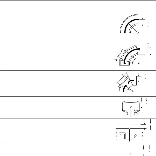
ASME B31.1-2010
MANDATORY APPENDIX D
Table D-1 Flexibility and Stress Intensification Factors
|
Flexibility |
Flexibility |
Stress |
|
|
Characteristic, |
Factor, |
Intensification Factor, |
|
Description |
h |
k |
i |
Sketch |
|
|
|
|
|
tn
r
Welding elbow or pipe bend |
tnR |
1.65 |
0.9 |
|
|
|
|
|
|
|
|
|
|
|||
|
|
|
|
|
|
|
|
|
|
|||||||
|
|
|
|
|
|
|
|
|
|
|||||||
|
|
|
|
|
|
|
|
|
|
|||||||
[Notes (1), (2), (3), (4), (5)] |
r 2 |
|
|
h |
|
h 2⁄3 |
|
|
R |
|
|
|
|
|
|
|
|
|
|
|
|
|
|
|
|
|
|
|
|||||
|
|
|
|
|
|
|
|
|
|
|
|
|
|
|
|
|
|
|
|
|
|
|
|
|
|
|
|
|
|
|
|
|
|
|
|
|
|
|
|
|
|
|
|
|
|
|
|
|
|
|
|
|
|
|
|
|
|
|
|
|
|
|
|
|
|
|
|
|
|
|
|
|
|
|
|
|
|
|
|
|
|
|
|
|
 tn
tn
Closely spaced miter bend [Notes (1), (2), (3), (5)] s < r (1 + tan )
B ≥ 6 tn
≤ 221⁄2 deg
stn cot |
1.52 |
0.9 |
|
s |
|
|
|
r |
||||||||
|
|
|
||||||||||||||
|
|
|
|
|
|
|
|
|||||||||
θ |
|
|
|
|
|
|
|
|||||||||
2r 2 |
|
h 5⁄6 |
|
h 2⁄3 |
|
|
|
|
|
|
|
|||||
|
|
|
|
|
|
|
|
|
||||||||
|
|
|
|
|
|
|
|
B |
|
R = |
|
s cot θ |
|
|||
|
|
|
|
|
|
|
|
|
|
|
||||||
|
|
|
|
|
|
|
|
|
|
|
|
|
|
|||
|
|
|
|
|
|
|
|
|
|
|
|
2 |
|
|
||
|
|
|
|
|
|
|
|
|
|
|
|
|
|
|
|
|
Widely spaced miter bend [Notes (1), (2), (5), (6)]
s≥ r (1 + tan )
≤ 221⁄2 deg
 θ
θ
tn (1 + cot ) |
1.52 |
0.9 |
s |
|
|
|
r |
|
|
|
|
|
tn |
|||||
|
|
|
|
|
||||||||||||||
|
|
|
|
|
|
|
|
|
|
|
||||||||
|
|
|
|
|
|
|
|
|
|
|||||||||
2r |
|
|
h 5⁄6 |
|
h 2⁄3 |
|
|
|
|
|
|
r (1 + cot θ) |
|
|||||
|
|
|
|
|
|
|
|
|
|
R = |
|
|||||||
|
|
|
|
|
|
|
|
|
|
|
||||||||
|
|
|
|
|
|
|
2 |
|||||||||||
|
|
|
|
|
|
|
|
|
|
|
|
|
||||||
|
|
|
|
|
|
|
|
|
|
|
|
|
|
|
|
|
|
|
Welding tee per |
3.1tn |
|
0.9 |
|
|
r |
|
|
|
|
||||
|
|
|
|
|||||||||||
ASME B16.9 [Notes (1), |
1 |
|
|
|
|
|
|
|
|
tn |
||||
|
Tc |
|
|
|
|
|
|
|||||||
|
|
|
|
|
|
|
|
|
|
|||||
(2), (7)] |
r |
|
h 2⁄3 |
|
|
|
|
|
|
|
|
|
|
|
|
|
|
|
|
|
|
|
|
|
|
||||
rx
Reinforced fabricated tee |
|
tn + |
tr |
5⁄2 |
0.9 |
||
|
|
|
|
1 |
|||
[Notes (1), (2), (8), (9)] |
|
2 |
|
|
h 2⁄3 |
||
|
|
r (tn) 3⁄2 |
|||||
|
|
|
|||||
|
r |
|
tn |
tr |
tr |
Pad |
Saddle |
|
|
|
|
|
|
|
|
|
|
|
|
|
|
|
|
|
|
|
|
|
|
Unreinforced fabricated tee |
tn |
1 |
0.9 |
|
|
|
|
|
|
|
|
r |
|
|
tn |
||||||
|
|||||||||||||||||||||
|
|
|
|
|
|
|
|
|
|
|
|
|
|
|
|||||||
|
|
|
|
|
|
|
|
|
|
|
|
|
|
|
|||||||
[Notes (1), (2), (9)] |
r |
|
|
h 2⁄3 |
|
|
|
|
|
|
|
|
|
|
|
|
|
|
|
|
|
|
|
|
|
|
|
|
|
|
|
|
|
|
|
|
|
|
|
||||
|
|
|
|
|
|
|
|
|
|
|
|
|
|
|
|
|
|
|
|||
|
|
|
|
|
|
|
|
|
|
|
|
|
|
|
|
|
|
|
|
|
|
|
|
|
|
|
|
|
|
|
|
|
|
|
|
|
|
|
|
|
|
|
|
|
|
|
|
|
|
|
|
|
|
|
|
|
|
|
|
|
|
|
|
|
|
-- |
|
-`,,```````,,```,`,`,,,,`,`,`,` |
220 |
|
|
Copyright ASME International |
|
-` |
|
Provided by IHS under license with ASME |
|
`,,`,,`,`,,` |
|
No reproduction or networking permitted without license from IHS |
|
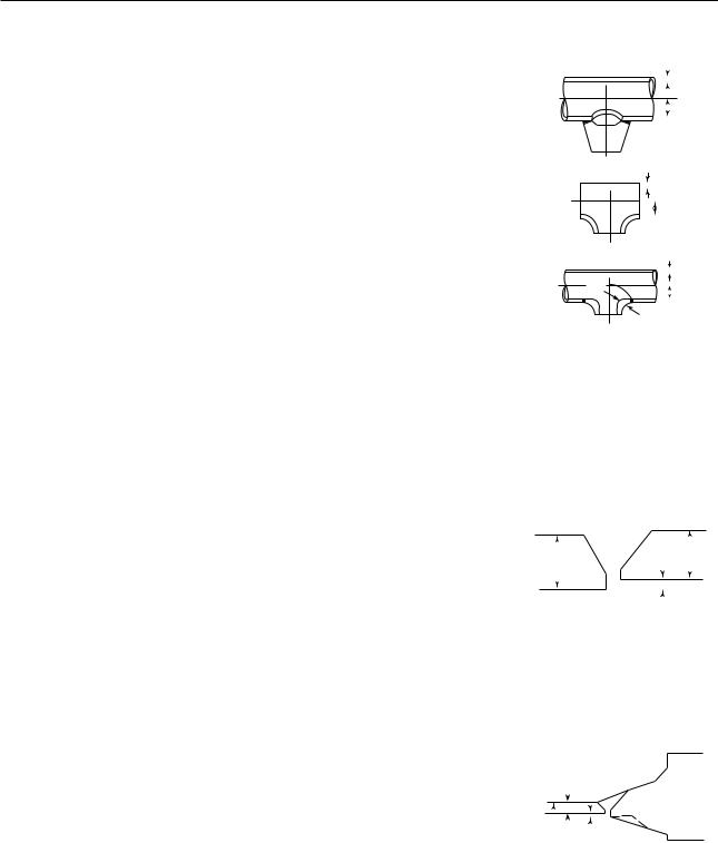
ASME B31.1-2010
Table D-1 Flexibility and Stress Intensification Factors (Cont’d)
|
Flexibility |
Flexibility |
|
|
|
|
|
|
|
Stress |
|
|
|
|
|
|
|
|
|
|
|
|
|
|
|
|
|
|
|
|
|
|
|
|
|
||||||||||||||||
|
Characteristic, |
Factor, |
|
|
Intensification Factor, |
|
|
|
|
|
|
|
|
|
|
|
|
|
|
|
|
|
|
|
|
|
|
|
|
||||||||||||||||||||||
Description |
|
|
h |
k |
|
|
|
|
|
|
|
|
|
|
|
i |
|
|
|
|
|
|
|
|
|
|
|
Sketch |
|
|
|
|
|
||||||||||||||||||
|
|
|
|
|
|
|
|
|
|
|
|
|
|
|
|
|
|
|
|
|
|
|
|
|
|
|
|
|
|
|
|
|
|
|
|
|
|
|
|
|
|
|
|
|
|
|
|
|
|
|
|
Branch welded-on fitting |
|
3.3tn |
|
|
|
|
|
|
|
|
|
|
0.9 |
|
|
|
|
|
|
|
|
|
|
|
|
|
|
|
|
|
|
|
|
|
tn |
||||||||||||||||
|
|
|
|
|
|
|
|
|
|
|
|
|
|
|
|
|
|
|
|
|
|
|
|
|
|
|
|
|
|
||||||||||||||||||||||
|
|
|
|
|
|
|
|
|
|
|
|
|
|
|
|
|
|
|
|
|
|
|
|
|
|
|
|
|
|
||||||||||||||||||||||
|
|
|
|
|
|
|
|
|
|
|
|
|
|
|
|
|
|
|
|
|
|
|
|
|
|
|
|
|
|
|
|
|
|
|
|||||||||||||||||
|
|
|
|
|
|
|
|
|
|
|
|
|
|
|
|
|
|
|
|
|
|
|
|
|
|
|
|
|
|
r |
|||||||||||||||||||||
|
|
|
|
|
|
|
|
|
|
|
|
|
|
|
|
|
|
|
|
|
|
|
|
|
|
|
|
|
|
||||||||||||||||||||||
|
|
|
|
|
|
|
|
|
|
|
|
|
|
|
|
|
|
|
|
|
|
|
|
|
|
|
|
|
|
||||||||||||||||||||||
(integrally reinforced) per |
|
1 |
|
|
|
|
|
|
|
|
|
|
|
|
|
|
|
|
|
|
|
|
|
|
|
|
|
|
|
|
|||||||||||||||||||||
|
|
|
|
|
|
|
|
|
|
|
|
|
|
|
|
|
|
|
|
|
|
|
|
|
|
|
|||||||||||||||||||||||||
|
|
|
|
|
|
|
|
|
|
|
|
|
|
|
|
|
|
|
|
|
|
|
|
|
|
|
|||||||||||||||||||||||||
MSS SP-97 [Notes (1), (2)] |
|
|
r |
|
|
|
|
|
|
|
|
|
|
|
h 2⁄3 |
|
|
|
|
|
|
|
|
|
|
|
|
|
|
|
|
|
|
|
|
|
|
|
|
|
|||||||||||
|
|
|
|
|
|
|
|
|
|
|
|
|
|
|
|
|
|
|
|
|
|
|
|
|
|
|
|
|
|
|
|
|
|
||||||||||||||||||
|
|
|
|
|
|
|
|
|
|
|
|
|
|
|
|
|
|
|
|
|
|
|
|
|
|
|
|
|
|
|
|
|
|
||||||||||||||||||
|
|
|
|
|
|
|
|
|
|
|
|
|
|
|
|
|
|
|
|
|
|
|
|
|
|
|
|
|
|
|
|
|
|
|
|
|
|
|
|
|
|
|
|
|
|
|
|
|
|
|
|
|
|
|
|
|
|
|
|
|
|
|
|
|
|
|
|
|
|
|
|
|
|
|
|
|
|
|
|
|
|
|
|
|
|
|
|
|
|
|
|
|
|
|
|
|
|
|
|
|
|
|
|
|
|
|
|
|
|
|
|
|
|
|
|
|
|
|
|
|
|
|
|
|
|
|
|
|
|
|
|
|
|
|
|
|
|
|
|
|
|
|
|
tn |
|
|
|
|
|
||||||
Extruded outlet meeting the |
|
|
tn |
|
|
|
|
|
|
|
|
|
|
0.9 |
|
|
|
|
|
|
|
|
|
|
|
|
|
|
|
|
|
|
|
|
|
|
|
|
|
|
|||||||||||
|
|
|
|
|
|
|
|
|
|
|
|
|
|
|
|
|
|
|
|
|
|
|
|
|
|
|
|
|
|
|
|
|
|
|
|
||||||||||||||||
requirements of para. |
|
|
1 |
|
|
|
|
|
|
|
|
|
|
|
|
|
|
|
|
|
|
|
|
|
|
|
|
|
|
|
|
|
|
|
|
|
|||||||||||||||
|
|
|
|
|
|
|
|
|
|
|
|
|
|
|
|
|
|
|
|
|
|
|
|
|
|
|
r |
|
|
|
|
|
|||||||||||||||||||
104.3.1(G) [Notes (1), (2)] |
|
|
r |
|
|
|
|
|
|
|
|
|
|
|
h 2⁄3 |
|
|
|
|
|
|
|
|
|
|
|
|
|
|
|
|
|
|
|
|
|
|
|
|
|
|||||||||||
|
|
|
|
|
|
|
|
|
|
|
|
|
|
|
|
|
|
|
|
|
|
|
|
|
|
|
|
|
|
|
|
|
|
|
|||||||||||||||||
|
|
|
|
|
|
|
|
|
|
|
|
|
|
|
|
|
|
|
|
|
|
|
|
|
|
|
|
|
|
|
|
|
|
|
|
|
|
|
|
|
|
|
|
|
|
|
|
|
|
|
|
|
|
|
|
|
|
|
|
|
|
|
|
|
|
|
|
|
|
|
|
|
|
|
|
|
|
|
|
|
|
|
|
|
|
|
|
|
|
|
|
|
|
|
|
|
|
|
|
tn |
|||
Welded-in contour insert |
|
|
|
tn |
1 |
|
|
|
|
|
|
|
0.9 |
|
|
|
|
|
|
|
|
|
Tc |
|
|
|
|
|
|
|
|||||||||||||||||||||
|
|
|
|
|
|
|
|
|
|
|
|
|
|
|
|
|
|
|
|
|
|
|
|
|
|
||||||||||||||||||||||||||
3.1 |
|
|
|
|
|
|
|
|
|
|
|
|
|
|
|
|
|
|
r |
|
|||||||||||||||||||||||||||||||
[Notes (1), (2), (7)] |
|
|
|
|
|
|
|
|
|
|
|
|
|
|
|
|
|
|
|
|
|
|
|
|
|
|
|
|
|
|
|
|
|
|
|
|
|
|
|
|
|
|
|
||||||||
r |
|
|
|
|
|
|
|
|
|
|
|
|
h 2⁄3 |
|
|
|
|
|
|
|
|
|
|
|
|
|
|
|
rx |
|
|
|
|
|
|||||||||||||||||
|
|
|
|
|
|
|
|
|
|
|
|
|
|
|
|
|
|
|
|
|
|
|
|
|
|
|
|
|
|
|
|
|
|
|
|
|
|
|
|
|
|
|
|
||||||||
|
|
|
|
|
|
|
|
|
|
|
|
|
|
|
|
|
|
|
|
|
|
|
|
|
|
|
|
|
|
|
|
|
|
|
|
|
|
|
|
|
|
|
|
|
|
||||||
|
Flexibility |
|
|
|
|
|
|
|
|
|
|
|
|
|
|
|
|
|
|
|
|
|
|
|
|
|
|
|
|
|
|
|
|
|
|
|
|
|
|
|
|
|
|
|
|||||||
|
Factor, |
Stress Intensification Factor, |
|
|
|
|
|
|
|
|
|
|
|
|
|
|
|
|
|
|
|
|
|
|
|
|
|||||||||||||||||||||||||
Description |
|
|
k |
|
|
|
|
|
|
|
i |
|
|
|
|
|
|
|
|
|
|
|
|
|
|
|
|
|
|
Sketch |
|
|
|
|
|
||||||||||||||||
|
|
|
|
|
|
|
|
|
|
|
|
|
|
|
|
|
|
|
|
|
|
|
|
|
|
|
|
|
|
|
|
|
|
|
|
|
|
|
|
|
|
|
|
|
|
|
|
||||
|
|
|
|
|
|
|
|
|
For checking branch end |
|
|
|
|
|
|
|
|
|
|
|
|
|
|
|
|
|
|
|
|
|
|
|
|
|
|
|
|
||||||||||||||
Branch connection |
|
|
|
|
|
|
|
|
|
Rm 2⁄3 |
r ′m 1⁄2 |
|
tnb |
|
r ′m |
|
|
|
|
|
|
|
|
|
|
|
|
|
|
|
|
|
|
|
|
|
|
|
|
|
|||||||||||
[Notes (1), (10)] |
1 |
|
|
|
1.5 |
|
|
|
|
|
|
|
|
|
|
|
|
|
|
|
|
|
|
|
See Fig. D-1 |
|
|
|
|
|
|||||||||||||||||||||
|
|
|
tnh |
Rm |
tnh |
rp |
|
|
|
|
|
|
|
|
|
||||||||||||||||||||||||||||||||||||
Butt weld [Note (1)] |
|
|
|
|
|
|
|
|
|
|
|
|
|
|
|
|
|
|
|
|
|
|
|
|
|
|
|
|
|
|
|
|
|
|
|
|
|
|
|
|
|
|
|
|
|
|
|
|
|
|
|
t ≥ 0.237 in., |
1 |
|
|
|
1.0 [Note (11)] |
|
|
|
|
|
|
|
|
|
|
|
|
|
|
|
|
|
|
|
|
|
|
|
|
|
|
|
|
|
|
|
|
|
|
|
|||||||||||
max ≤ 1⁄16 in., |
|
|
|
|
|
|
|
|
|
|
|
|
|
|
|
|
|
|
|
|
|
|
|
|
|
|
|
|
|
|
|
|
|
|
|
|
|
|
|
|
|
|
|
|
|
|
|
|
|
|
|
and avg /t ≤ 0.13 |
|
|
|
|
|
|
|
|
|
|
|
|
|
|
|
|
|
|
|
|
|
|
|
|
|
|
|
|
|
|
|
|
|
|
|
|
|
|
|
|
|
|
|
|
|
|
|
|
|
|
t |
|
|
|
|
|
|
|
|
|
|
|
|
|
|
|
|
|
|
|
|
|
|
|
|
|
|
|
|
|
|
|
|
|
|
|
|
|
|
|
|
|
|
|
|
|
|
|
|
|
|
||
Butt weld [Note (1)] |
|
|
|
|
|
|
|
|
|
|
|
|
|
|
|
|
|
|
|
|
|
|
|
|
|
|
|
|
|
t |
|
|
|
|
|
|
|
|
|
|
|
|
|
|
|
|
|
|
|
||
t ≥ 0.237 in., |
1 |
|
|
|
|
|
|
|
|
|
|
|
|
|
|
|
|
|
|
|
|
|
|
|
|
|
|
|
|
|
|
|
|
|
|
|
|
|
|
|
|
|
|
|
|
||||||
|
|
|
|
|
|
|
|
|
|
|
|
|
|
|
|
|
|
|
|
|
|
|
|
|
|
|
|
|
|
|
|
|
|
|
|
|
|
|
|
|
|
|
|
|
|
||||||
|
|
|
|
|
|
|
|
|
|
|
|
|
|
|
|
|
|
|
|
|
|
|
|
|
|
|
|
|
|
|
|
|
|
|
|
|
|
|
|
|
|
|
|
|
|
||||||
|
|
|
|
|
|
|
|
|
|
|
|
|
|
|
|
|
|
|
|
|
|
|
|
|
|
|
|
|
|
|
|
|
|
|
|
|
|
|
|
|
|
|
|
|
|
||||||
max ≤ 1⁄8 in., |
|
|
|
|
|
|
|
|
1.9 max. or [0.9 + 2.7( avg /t)], |
|
|
|
|
|
|
|
|
|
|
|
|
|
|
|
|
|
|
|
|
δ |
|||||||||||||||||||||
|
|
|
|
|
|
|
|
|
|
|
|
|
|
|
|
|
|
|
|
|
|
|
|
|
|
|
|
||||||||||||||||||||||||
and avg /t p any value |
|
|
|
|
|
|
|
|
|
|
|
|
|
|
|
|
|
|
|
|
|
|
|
|
|
|
|
|
|
|
|
|
|
||||||||||||||||||
|
|
|
|
|
|
|
|
but not less than 1.0 |
|
|
|
|
|
|
|
|
|
|
|
|
|
|
|
|
|
|
|
|
|
|
|
|
|
|
|
|
|||||||||||||||
|
|
|
|
|
|
|
|
|
|
|
|
|
|
|
|
|
|
|
|
|
|
|
|
|
|
|
|
|
|
|
|
|
|
|
|
|
|||||||||||||||
Butt weld [Note (1)] |
|
|
|
|
|
|
|
|
[Note (11)] |
|
|
|
|
|
|
|
|
|
|
|
|
|
|
|
|
|
|
|
|
|
|
|
|
|
|
|
|
|
|
|
|
|
|
|
|
|
|
|
|
||
t < 0.237 in., |
1 |
|
|
|
|
|
|
|
|
|
|
|
|
|
|
|
|
|
|
|
|
|
|
|
|
|
|
|
|
|
|
|
|
|
|
|
|
|
|
|
|
|
|
|
|
|
|
||||
max ≤ 1⁄16 in., |
|
|
|
|
|
|
|
|
|
|
|
|
|
|
|
|
|
|
|
|
|
|
|
|
|
|
|
|
|
|
|
|
|
|
|
|
|
|
|
|
|
|
|
|
|
|
|
|
|
|
|
and avg /t ≤ 0.33 |
|
|
|
|
|
|
|
|
|
|
|
|
|
|
|
|
|
|
|
|
|
|
|
|
|
|
|
|
|
|
|
|
|
|
|
|
|
|
|
|
|
|
|
|
|
|
|
|
|
|
|
|
|
|
|
|
|
|
|
|
|
|
|
|
|
|
|
|
|
|
|
|
|
|
|
|
|
|
|
|
|
|
|
|
|
||||||||||||||||||
Fillet welds |
1 |
|
|
|
1.3 [Note (12)] |
|
|
|
|
|
|
|
|
|
|
|
See Figs. 127.4.4(A), 127.4.4(B), and |
||||||||||||||||||||||||||||||||||
|
|
|
|
|
|
|
|
|
|
|
|
|
|
|
|
|
|
|
|
|
127.4.4(C) |
|
|
|
|
|
|||||||||||||||||||||||||
|
|
|
|
|
|
|
|
|
|
|
|
|
|
|
|
|
|
|
|
|
|
|
|
|
|
|
|
|
|
|
|
|
|
|
|
|
|
|
|
||||||||||||
|
|
|
|
|
|
|
|
|
|
|
|
|
|
|
|
|
|
|
|
|
|
|
|
|
|
|
|
|
|
|
|
|
|
|
|
|
|
|
|
|
|
|
|
|
|
|
|
|
|
|
|
|
|
|
|
|
|
|
|
|
1.9 max. or |
|
|
|
|
|
|
|
|
|
|
|
|
|
|
|
|
|
|
tn |
|
|
|
|
|
|
|
|
|
|
|
|
|
|
|
|
|
|
|
|
|||
Tapered transition per para. |
|
|
|
|
|
|
|
|
|
|
|
|
|
|
|
|
|
|
|
|
|
|
|
|
|
|
|
|
|
|
|
|
|
|
|
|
|
|
|
|
|
|
|
|
|
|
|
|
|||
|
|
|
|
|
|
|
|
|
|
|
|
|
|
|
|
|
|
|
|
|
|
|
|
|
|
|
|
|
|
|
|
|
|
|
|
|
|
|
|
|
|
|
|
|
|
|
|
|
|
|
|
127.4.2(B) and |
1 |
|
|
|
|
|
|
|
|
Do |
|
|
|
|
|
|
|
|
|
|
|
|
|
|
|
|
|
|
|
|
|
|
|
|
|
|
|
|
|
|
|
||||||||||
ASME B16.25 [Note (1)] |
|
|
|
|
|
|
|
|
|
|
|
|
|
|
|
|
|
|
|
|
|
|
|
|
|
|
|
|
|
|
|
|
|
|
|
|
|
|
|
|
|
|
|
||||||||
|
|
|
|
|
|
|
|
|
|
|
|
|
|
|
|
|
|
|
|
|
|
|
|
|
|
|
|
|
|
|
|
|
|
|
|
|
|
|
|
|
|
|
|||||||||
|
|
|
|
|
|
|
|
|
1.3 + 0.0036 |
tn |
+ 3.6 |
tn |
|
|
|
|
|
Do |
|
|
|
|
|
|
|
|
|
|
|
|
|
|
|
|
|
|
|
|
|
|
|
||||||||||
|
|
|
|
|
|
|
|
|
|
|
|
|
|
|
|
|
|
|
|
|
|
|
|
|
|
|
|
|
|
|
|
δ |
|
|
|
|
|
||||||||||||||
|
|
|
|
|
|
|
|
|
|
|
|
|
|
|
|
|
|
|
|
|
|
|
|
|
|
|
|
|
|
|
|
|
|
|
|
|
|
||||||||||||||
|
|
|
|
|
|
|
|
|
|
|
|
|
|
|
|
|
|
|
|
|
|
|
|
|
|
|
|
|
|
|
|
|
|
|
|
|
|
|
|
|
|
|
|
|
|
|
|
|
|
|
|
221
--`,,```````,,```,`,`,,,,`,`,`,`-`-`,,`,,`,`,,`---
Copyright ASME International
Provided by IHS under license with ASME
No reproduction or networking permitted without license from IHS
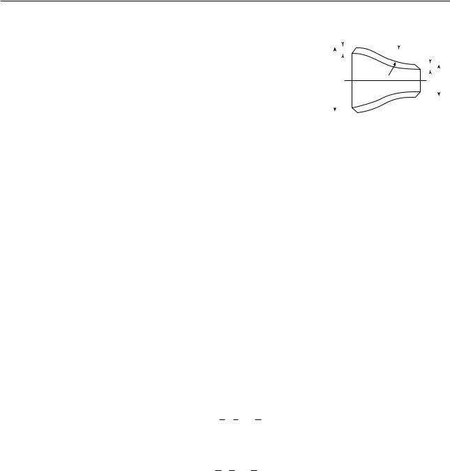
ASME B31.1-2010
Table D-1 Flexibility and Stress Intensification Factors (Cont’d)
|
|
Flexibility |
Stress Intensification Factor, |
|
|
|
|
|
|
|
|
|
|
|
|
|
|
|
|||
Description |
Factor, k |
|
i |
|
|
|
|
|
Sketch |
|
|
|
|
|
|
||||||
|
|
|
|
|
|
|
|
|
|
|
|
|
|
|
|
|
|
|
|
|
|
|
|
|
2.0 max. or |
|
|
|
t1 |
|
|
|
|
|
|
|
t2 |
||||||
|
|
|
|
|
|
|
|
|
|
|
|
|
|||||||||
|
|
|
|
|
|
|
|
|
|
|
|
|
|
||||||||
|
|
|
|
|
|
|
|
|
|
|
|
|
|
||||||||
|
|
|
|
|
|
|
|
|
|
|
|
|
|
||||||||
Concentric reducer per |
1 |
|
|
|
|
|
|
|
|
|
|
α |
|
|
|
|
|
|
|||
|
|
|
|
|
|
|
|
|
|
|
|
|
|
||||||||
|
|
|
|
|
|
|
|
|
|
|
|
|
|
|
|
|
|
|
|||
|
|
|
|
|
|
|
|
|
|
|
|
|
|
|
|
|
|
|
|||
ASME B16.9 [Note (13)] |
0.5 + 0.01 |
D2 |
1Ú2 |
|
D1 |
|
|
|
|
|
|
|
|
|
D2 |
||||||
|
|
|
|
|
|
|
|
|
|
|
|||||||||||
|
|
|
|
|
|
|
|
|
|
|
|
|
|||||||||
|
|
|
t2 |
|
|
|
|
|
|
|
|
|
|
|
|||||||
|
|
|
|
|
|
|
|
|
|
|
|
|
|
|
|
|
|
||||
|
|
|
|
|
|
|
|
|
|
|
|
|
|
|
|
|
|
|
|
|
|
|
|
|
|
|
|
|
|
|
|
|
|
|
|
|
|
|
|
|
|
|
|
|
|
|
|
|
|
|
|
|
|
|
|
|
|
|
|
|
|
|
|
|
|
Threaded pipe joint or |
1 |
2.3 |
|
|
|
|
|
. . . |
|
|
|
|
|
|
|
|
|||||
threaded flange |
|
|
|
|
|
|
|
|
|
|
|
|
|
||||||||
|
|
|
|
|
|
|
|
|
|
|
|
|
|
|
|
|
|
|
|
||
|
|
|
|
|
|
|
|
|
|
|
|
|
|
|
|
|
|
|
|
|
|
Corrugated straight pipe, or |
|
|
|
|
|
|
|
|
|
|
|
|
|
|
|
|
|
|
|
|
|
corrugated or creased bend |
5 |
2.5 |
|
|
|
|
|
. . . |
|
|
|
|
|
|
|
|
|||||
[Note (14)] |
|
|
|
|
|
|
|
|
|
|
|
|
|
|
|
|
|
|
|
|
|
|
|
|
|
|
|
|
|
|
|
|
|
|
|
|
|
|
|
|
|
|
|
NOTES: |
|
|
|
|
|
|
|
|
|
|
|
|
|
|
|
|
|
|
|
|
|
(1) The following nomenclature applies to Table D-1: |
|
|
|
|
|
|
|
|
|
|
|
|
|
|
|
|
|
|
|
||
B p length of miter segment at crotch, in. (mm) |
|
|
|
|
|
|
|
|
|
|
|
|
|
|
|
||||||
Do |
p outside diameter, in. (mm) |
|
|
|
|
|
|
|
|
|
|
|
|
|
|
|
|
|
|
|
|
Dob |
p outside diameter of branch, in. (mm) |
|
|
|
|
|
|
|
|
|
|
|
|
|
|
|
|
|
|
|
|
R p bend radius of elbow or pipe bend, in. (mm) |
|
|
|
|
|
|
|
|
|
|
|
|
|
|
|
||||||
r |
p mean radius of pipe, in. (mm) (matching pipe for tees) |
|
|
|
|
|
|
|
|
|
|
|
|
|
|
|
|||||
rx |
p external crotch radius of welded-in contour inserts and welding tees, in. (mm) |
|
|
|
|
|
|
|
|
|
|
|
|
|
|
|
|||||
s |
p miter spacing at centerline, in. (mm) |
|
|
|
|
|
|
|
|
|
|
|
|
|
|
|
|
|
|
|
|
Tc |
p crotch thickness of welded-in contour inserts and welding tees, in. (mm) |
|
|
|
|
|
|
|
|
|
|
|
|
|
|
|
|||||
tn |
p nominal wall thickness of pipe, in. (mm) (matching pipe for tees) |
|
|
|
|
|
|
|
|
|
|
|
|
|
|
|
|||||
tr |
p reinforcement pad or saddle thickness, in. (mm) |
|
|
|
|
|
|
|
|
|
|
|
|
|
|
|
|||||
p reducer cone angle, deg
p mismatch, in. (mm)
p one-half angle between adjacent miter axes, deg
(2)The flexibility factors k and stress intensification factors i in Table D-1 apply to bending in any plane for fittings and shall in no case be taken less than unity. Both factors apply over the effective arc length (shown by heavy centerlines in the sketches) for curved and miter elbows, and to the intersection point for tees. The values of k and i can be read directly from Chart D-1 by entering with the characteristic h computed from the formulas given.
(3)Where flanges are attached to one or both ends, the values of k and i in Table D-1 shall be multiplied by the factor c given below, which can be read directly from Chart D-2, entering with the computed h: one end flanged, c p h1/6; both ends flanged, c p h1/3.
(4)The designer is cautioned that cast butt welding elbows may have considerably heavier walls than those of the pipe with which they are used. Large errors may be introduced unless the effect of these greater thicknesses is considered.
(5)In large diameter thin-wall elbows and bends, pressure can significantly affect magnitudes of k and i. Values from the Table may be corrected by dividing k by
1 + 6 EPc trn 7/3 Rr 1/3
and dividing i by
1 + 3.25 EPc trn 5/2 Rr 2/3
(6)Also includes single miter joints.
(7)If rx ≥ Dob/8 and Tc ≥ 1.5tn, a flexibility characteristic, h, of 4.4tn/r may be used.
(8)When tr > 1.5tn, h p 4.05tn /r.
(9)The stress intensification factors in the Table were obtained from tests on full size outlet connections. For less than full size outlets, the full size values should be used until more applicable values are developed.
222
--`,,```````,,```,`,`,,,,`,`,`,`-`-`,,`,,`,`,,`---
Copyright ASME International
Provided by IHS under license with ASME
No reproduction or networking permitted without license from IHS
ASME B31.1-2010
Table D-1 Flexibility and Stress Intensification Factors (Cont’d)
NOTES (Cont’d):
(10)The equation applies only if the following conditions are met:
(a)The reinforcement area requirements of para. 104.3 are met.
(b)The axis of the branch pipe is normal to the surface of run pipe wall.
(c)For branch connections in a pipe, the arc distance measured between the centers of adjacent branches along the surface of the run pipe is not less than three times the sum of their inside radii in the longitudinal direction or is not less than two times the sum of their radii along the circumference of the run pipe.
(d)The inside corner radius r1 (see Fig. D-1) is between 10% and 50% of tnh.
(e) |
The outer radius r2 (see Fig. D-1) is not less than the larger of Tb /2, (Tb + y)/2 [shown in Fig. D-1 sketch (c)], or tnh /2. |
|
|
(f ) |
The outer radius r3 (see Fig. D-1) is not less than the larger of: |
|
|
(1) 0.002 do; |
|
||
(2) 2(sin )3 times the offset for the configurations shown in Fig. D-1 sketches (a) and (b). |
|
||
(g) |
Rm /tnh ≤ 50 and r ′m /Rm ≤ 0.5. |
|
|
(11) The stress intensification factors apply to girth butt welds between two items for which the wall thicknesses are between 0.875t and |
|
||
1.10t for an axial distance of Dot. Do and t are nominal outside diameter and nominal wall thickness, respectively. avg is the aver- |
|
||
age mismatch or offset. |
|
||
(12) For welds to socket welded fittings, the stress intensification factor is based on the assumption that the pipe and fitting are matched |
|
||
in accordance with ASME B16.11 and a full weld is made between the pipe and fitting as shown in Fig. 127.4.4(C). For welds to |
--- |
||
`,,`,,`,`,,`- |
|||
to envelop the results of the pipe to socket welded fitting tests. Blending the toe of the fillet weld, with no undercut, smoothly into |
|||
socket welding flanges, the stress intensification factor is based on the weld geometry shown in Fig. 127.4.4(B) and has been shown |
|
||
the pipe wall, as shown in the concave fillet welds in Fig. 127.4.4(A) sketches (b) and (d), has been shown to improve the fatigue |
-` |
||
`,,```````,,```,`,`,,,,`,`,`,`-- |
|||
(c) |
The wall thickness is not less than t1 throughout the body of the reducer, except in and immediately adjacent to the cylindrical |
||
performance of the weld. |
|
||
(13) The equation applies only if the following conditions are met: |
|
||
(a) |
Cone angle does not exceed 60 deg, and the reducer is concentric. |
|
|
(b) |
The larger of D1/t1 and D2/t2 does not exceed 100. |
|
|
portion on the small end, where the thickness shall not be less than t2. (14) Factors shown apply to bending; flexibility factor for torsion equals 0.9.
223
Copyright ASME International
Provided by IHS under license with ASME
No reproduction or networking permitted without license from IHS