

15.7. ETHERNET NETWORKS |
1067 |
15.7.2Ethernet cabling
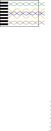
Along with hubs came another form of Ethernet cable and connector: unshielded, twisted pair (UTP) wiring and RJ-45 “flat” connectors. These cables use multiple twisted pairs of wires instead of the coaxial cable specified in Metcalfe’s original Ethernet. The purpose of using twisted-wire pairs is to reduce magnetic signal coupling (for more information, refer to section 8.3.6 beginning on page 625).
|
RJ-45 cable connector |
1 |
Wht/Grn |
2 |
Grn/Wht |
3 |
Wht/Org |
4 |
Blu/Wht |
5 |
Wht/Blu |
6 |
Org/Wht |
7 |
Wht/Brn |
8 |
Brn/Wht |
For 10 Mbps Ethernet over UTP cable (called 10BASE-T) and for 100 Mbps Ethernet (called 100BASE-TX), only two54 out of four available wire pairs are used:
Pin number |
Assignment |
Abbreviation |
1 |
Transmit Data (+) |
TD+ |
|
|
|
2 |
Transmit Data (−) |
TD− |
3 |
Receive Data (+) |
RD+ |
|
|
|
4 |
(not used) |
|
|
|
|
5 |
(not used) |
|
|
|
|
6 |
Receive Data (−) |
RD− |
7 |
(not used) |
|
8 |
(not used) |
|
|
|
|
It should be noted that 1000 Mbps (“Gigabit”) Ethernet over twisted-wire pairs does in fact use all four pairs in an eight-wire cable, a departure from traditional UTP Ethernet cable wiring:
|
Pin number |
Assignment |
Abbreviation |
|
1 |
Pair “A” (+) |
BI DA+ |
|
|
|
|
|
2 |
Pair “A” (−) |
BI DA− |
|
3 |
Pair “B” (+) |
BI DB+ |
|
|
|
|
|
4 |
Pair “C” (+) |
BI DC+ |
|
5 |
Pair “C” (−) |
BI DC− |
|
6 |
Pair “B” (−) |
BI DB− |
|
7 |
Pair “D” (+) |
BI DD+ |
|
|
|
|
|
8 |
Pair “D” (−) |
BI DD− |
|
|
|
|
54With only half the available wire pairs used in a standard 10 Mbps or 100 Mbps Ethernet cable, this opens the possibility of routing two Ethernet channels over a single four-pair UTP cable and RJ-45 connector. Although this is non-standard wiring, it may be a useful way to “squeeze” more use out of existing cables in certain applications. In fact, “splitter” devices are sold to allow two RJ-45-tipped cables to be plugged into a single RJ-45 socket such that one four-pair cable will then support two Ethernet pathways.
1068 |
CHAPTER 15. DIGITAL DATA ACQUISITION AND NETWORKS |
Along with UTP cables and RJ-45 connectors came a significant alteration to the basic electrical scheme of Ethernet. Metcalfe’s original design used a simple coaxial cable as the “ether” connecting devices together. Such cables had only two conductors, meaning each device needed to transmit and receive data over the same two conductors. With UTP cable’s four pairs of conductors, transmission and reception of signals occurs over di erent wire pairs55. This means connections made between Ethernet devices must employ a “swap” between TD and RD wire pairs in order for communication to take place, so that the “receiver” circuitry of one device connects to the “transmitter” circuitry of the other, and vice-versa. This is precisely the same characteristic inherent to EIA/TIA-232 and four-wire EIA/TIA-485 networks, where separate wire pairs are dedicated to “transmit” and “receive” functions.
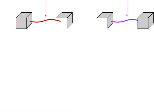
In a typical Ethernet system, the interconnecting hubs perform this transmit/receive swap. Hubs are considered DCE devices, while computers and other end-of-the-line devices are considered DTE devices. This means the pin assignments of DTE and DCE devices must be di erent in order to ensure the transmit/receive pin swap necessary for straight-through cables to work. This also means if someone ever wishes to directly connect two Ethernet DTE devices together without the benefit of a hub in between, a special crossover cable must be used for the connection, identical in function to the null modem cable used to connect two EIA/TIA-232 DTE devices together:
A regular "straight" Ethernet |
You must use a crossover |
cable will not work here! |
cable in this application! |
Ethernet
DTE device
|
Ethernet |
|
Ethernet |
Wrong |
DTE |
|
DTE |
device |
|
device |
|
|
|
|
|
Ethernet
DTE
Correct device
55This means modern Ethernet is capable of full-duplex communication between two devices, whereas the original coaxial-based Ethernet was only capable of half-duplex communication.
15.7. ETHERNET NETWORKS |
1069 |
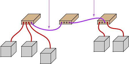
Furthermore, the same problem exists when multiple hubs are connected to form larger networks. Since each hub is a DCE device, a straight-through cable connecting two hubs together will pass transmitted signals from one hub directly to the “transmit” pins of the other hub, not the “receive” pins as it needs to. Consequently, a “crossover” cable should be used to connect two Ethernet hubs together in order to avoid this problem:
|
Crossover cable |
Crossover cable |
Hub |
Hub |
Hub |
(DCE device) |
(DCE device) |
(DCE device) |
|
|
|
|
Ethernet |
Ethernet |
|
|
DTE |
DTE |
Ethernet |
Ethernet |
device |
device |
DTE |
DTE |
|
|
device |
device |
Ethernet |
|
|
|
|
|
|
|
DTE |
|
|
|
device |
|
1070 |
CHAPTER 15. DIGITAL DATA ACQUISITION AND NETWORKS |
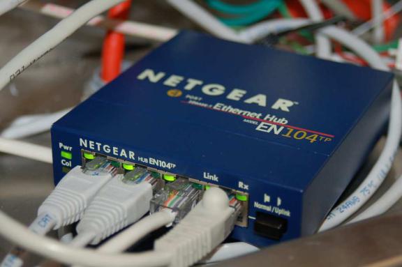
Some early Ethernet hubs provided a di erent solution to the “crossover” problem, and that was a crossover switch built into the hub, allowing a person to manually switch the transmit and receive wire pairs with the push of a button. In this next photograph of a four-port Ethernet hub, you can see the “Normal/Uplink” pushbutton on the right-hand side of the front panel, controlling the furthest-right port of the hub. This switch is supposed to be placed in the “Normal” position if the device plugged into that port is a DTE device, and placed in the “Uplink” position if the device is a DCE device (e.g. another hub):
Note the LED indicator lights by each port on the hub. One LED indicates whether or not the cable is active (when a powered Ethernet DTE device is plugged into that port of the hub), while the other LED indicates tra c on the cable (by blinking). These LEDs are very helpful for identifying a crossover problem. This hub even has an LED indicating the occurrence of collisions (the “Col” LED just below the main power LED), giving simple visual indication of collision frequency.
Newer Ethernet DTE and DCE devices use auto-sensing technology to perform any necessary transmit/receive pin swaps, rendering crossover cables and crossover pushbuttons unnecessary for either DTE-to-DTE or hub-to-hub connections. Auto-sensing is a standard feature of 1000BASE-T (“Gigabit” Ethernet).