

plc serial - 27.15
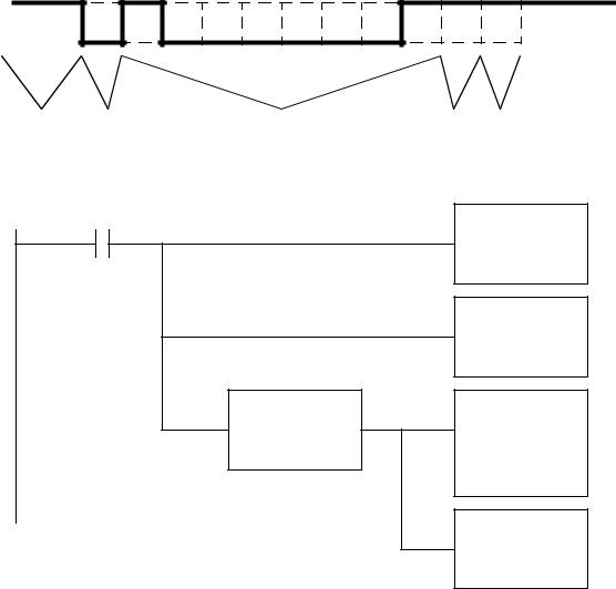
part waiting |
box full |
feed part
part waiting
ONS |
|
AWT |
|
Bit B3:0 |
|
|
Channel 0 |
|
|
||
|
|
|
String ST10:0 |
|
|
|
Length 6 |
ST10:0 = "pickup"
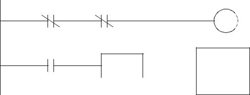
Figure 27.13 A Box Loading System
27.5SUMMARY
•Serial communications pass data one bit at a time.
•RS-232 communications use voltage levels for short distances. A variety of communications cables and settings were discussed.
•ASCII functions are available of PLCs making serial communications possible.
27.6PRACTICE PROBLEMS
1.Describe what the bits would be when an A (ASCII 65) is transmitted in an RS-232 interface with 8 data bits, even parity and 1 stop bit.
2.Divide the string in ST10:0 by the string in ST10:1 and store the results in ST10:2. Check for a divide by zero error.
ST10:0 “100”
ST10:1 “10”
ST10:2
3.How long would it take to transmit an ASCII file over a serial line with 8 data bits, no parity, 1 stop bit? What if the data were 7 bits long?
4.Write a number guessing program that will allow a user to enter a number on a terminal that transmits it to a PLC where it is compared to a value in N7:0. If the guess is above "Hi" will be returned. If below "Lo" will be returned. When it matches "ON" will be returned.
plc serial - 27.16
5.Write a program that will convert a numerical value stored in F8:0 and write it out the RS-232 output on a PLC-5 processor.
27.7 PRACTICE PROBLEM SOLUTIONS
1.
before |
start |
data |
parity |
stop |
2.
NEQ
Source A 0
Source B N7:1
ACI
Source ST10:0
Dest N7:0
ACI
Source ST10:1
Dest N7:1
DIV
Source A N7:0
Source B N7:1
Dest N7:2
AIC
Source N7:2
Dest ST10:2
3.If we assume 9600 baud, for (1start+8data+0parity+1stop)=10 bits/byte we get 960 bytes per second. If there are only 7 data bits per byte this becomes 9600/9 = 1067 bytes per second.

plc serial - 27.17
4.
|
|
R6:4/EN |
|
|
ACB |
|
|
|
|
|
|
|
|
|
|
|
|
|
|
Channel 0 |
|
|
|
|
|
|
|
|
|
|
|
|
|
Control R6:4 |
|
|
|
|
|
|
|
|
|
|
|
|
|
|
|
|
|
|
|
|
ARL |
|
|
EQU |
|
|
||
|
|
|
|
Channel 0 |
||
|
|
SourceA R6:4.POS |
|
|
||
|
|
|
|
Dest ST9:0 |
||
|
|
Source B 2 |
|
|
||
|
|
|
|
Control R6:0 |
||
|
|
|
|
|
|
|
|
|
|
|
|
|
Length 3 |
R6:0/DN |
|
|
||||
|
|
|
||||
|
|
|
||||
|
|
ACI |
||||
|
|
|
|
|
|
|
|
|
|
|
|
|
Source ST9:0 |
|
|
|
|
|
|
|
|
|
|
|
|
|
Dest N7:1 |
|
|
|
|
|
|
|
|
|
|
|
|
|
|
|
|
|
|
LES |
|
AWT |
|
|
|
|
Source A N7:1 |
|
Channel 0 |
|
|
|
|
|
||
|
|
|
|
Source B N7:0 |
|
Source ST9:1 |
|
|
|
|
|
|
Control R6:1 |
|
|
|
|
|
|
|
|
|
|
|
|
|
Length 2 |
|
|
|
|
|
|
|
|
|
|
|
EQ |
|
AWT |
ST9:1="Lo" |
|
Source A N7:1 |
|
Channel 0 |
||
|
|
|||||
|
Source B N7:0 |
|
Source ST9:2 |
|||
ST9:2="ON" |
|
|
||||
|
|
|
Control R6:2 |
|||
ST9:3="Hi" |
|
|
|
|||
|
|
|
Length 2 |
|||
|
|
|
|
|
|
|
|
|
|
|
|
|
|
|
|
|
|
GRT |
|
AWT |
|
|
|
|
Source A N7:1 |
|
Channel 0 |
|
|
|
|
|
||
|
|
|
|
Source B N7:0 |
|
Source ST9:3 |
|
|
|
|
|
||
|
|
|
|
|
|
Control R6:3 |
|
|
|
|
|
|
|
|
|
|
|
|
|
Length 2 |
plc serial - 27.18
5.
R6:0/EN
MOV
Source F8:0
Dest N7:0
AIC
Source N7:0
Dest ST9:0
AWT |
|
ASCII WRITE |
|
Channel |
0 |
Source |
ST9:0 |
Control |
R6:0 |
String Length |
5 |
Characters Sent |
|
27.8 ASSIGNMENT PROBLEMS
1.Describe an application of ASCII communications.
2.Write a ladder logic program to output an ASCII warning message on channel 1 when the value in N7:0 is less than 10, or greater than 20. The message should be "out of temp range".
3.Write a program that will send an ASCII message every minute. The message should begin with the word ‘count’, followed by a number. The number will be 1 on the first scan of the PLC, and increment once each minute.
4.A PLC will be controlled by ASCII commands received through the RS-232C communications port. The commands will cause the PLC to move between the states shown in the state dia-

plc serial - 27.19
gram. Implement the ladder logic.
FS
“start”
IDLE
“estop”
ACTIVE
“reset”
FAULT |
“error” |
|
5.A program is to be written to control a robot through an RS-232c interface. The robot has already been programmed to respond to two ASCII strings. When the robot receives the string ‘start’ it will move a part from a feeder to a screw machine. When the robot receives an ‘idle’ command it will become inactive (safe). The PLC has ‘start’ and ‘end’ inputs to control the process. The PLC also has two other inputs that indicate when the parts feeder has parts available (‘part present’) and when the screw machine is done (‘machine idle’). The ‘start’ button will start a cycle where the robot repeatedly loads parts into the screw machine whenever the ‘machine idle’ input is true. If the ‘part present’ sensor is off (i.e., no parts), or the ‘end’ input is off (a stop requested), the screw machine will be allowed to finish, but then the process will stop and the robot will be sent the idle command. Use a structured design method (e.g., state diagrams) to develop a complete ladder logic program to perform the task.
6.A PLC-5 is connected to a scale that measures weights and then sends an ASCII string. The string format is ‘XXXX.XX’. So a weight of 29.9 grams would result in a string of ‘0029.90’. The PLC is to read the string and then check to see if the weight is between 18.23 and 18.95 grams. If it is not then an error output light should be set until a reset button is pushed.