

4 Imaging the Postoperative Scalp and Cranium |
139 |
|
|
4.11\ Autocranioplasty
4.11.1\ Discussion
Several options are available for storing autologous bone flaps after decompressive craniectomy for delayed autocranioplasty. Often, bone flaps are stored in a sterile freezer. This approach preserves the bone flap very well, providing
a
b
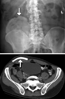
good cosmetic results. An alternative is subcutaneous storage, which allows the bone flap to stay with the patient and may decrease the risk of devitalization and/or infection of the flap. Bone flaps can be kept fresh by implanting them into subcutaneous pockets in the abdomen and may be encountered on imaging (Fig. 4.29). Bone grafts stored in this manner tend to undergo remodeling.
Fig. 4.29 Autocranioplasty. Frontal radiograph (a) and axial CT image (b) show a skull flap (arrows) embedded within the right lower quadrant subcutaneous tissues
140 |
D.T. Ginat et al. |
|
|
4.12\ Craniectomy,
the Meningogaleal Complex,
and Suboccipital Craniectomy
4.12.1\ Discussion
Decompressive craniectomy is performed in order to decrease intracranial pressure when medical management alone is insufficient and is most commonly used in the setting of traumatic brain injury, subarachnoid hemorrhage, intraparenchymal hemorrhage, and cerebral infarction. The procedure consists of removal of portions of the skull, which is not replaced during the procedure. Hemicraniectomy is performed when one side of the brain is affected and usually entails removal of bone in the frontoparietotemporal region. On the
a
other hand, bilateral (bifrontal) craniectomy is performed when both sides of the brain are affected and consists of removing the calvarium of the anterior cranial fossa to the coronal sutures.
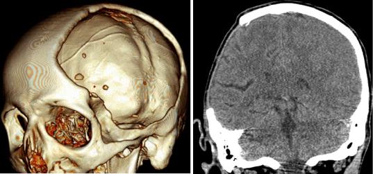
Decompressive craniectomy has characteristic imaging findings. Following craniectomy, the galea aponeurotica becomes juxtaposed against the dura. Scar tissue then forms between these two layers, which creates the meningogaleal complex beneath the subcutaneous tissues. Normally, this complex measures between 2 and 6 mm in thickness. On CT, the meningogaleal complex is slightly hyperattenuating, while the appearance on MRI is variable depending on the degree of hypervascular tissue that is incorporated (Fig. 4.30). Smooth, uniform enhancement is expected on CT and MRI.
b
Fig. 4.30 Craniectomy and normal meningogaleal complex.3D (a) and coronal (b) CT images show a large right hemicraniectomy defect and a normal meningogaleal complex in which the dura is juxtaposed to the scalp.
Axial T2-weighted (c), T1-weighted (d), and post-contrast T1-weighted (e) MRI sequences in a different patient show enhancement of the left hemicraniectomy meningogaleal complex (arrows)
4 Imaging the Postoperative Scalp and Cranium |
141 |
|
|
c |
d |
e
Fig. 4.30 (continued)
142 |
D.T. Ginat et al. |
|
|
4.13\ Cranial Vault Surgical Remodeling
for Craniosynostosis
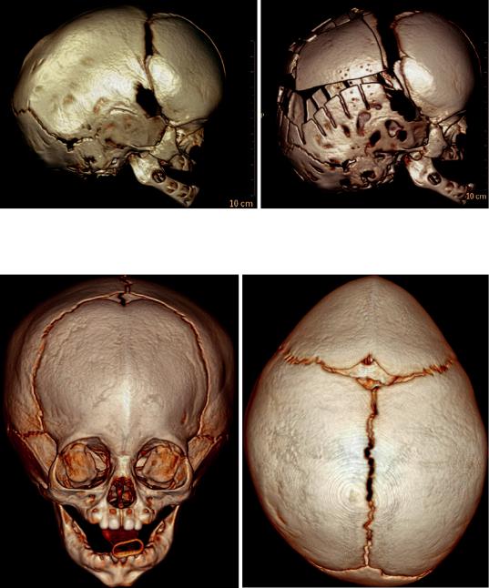
Sagittal synostosis is a relatively common type of craniosynostosis that results from premature fusion of the sagittal suture. Surgery is performed for relieving associated elevated intracranial pressure and for cosmesis. There are several approaches to correcting the deformity including bone removal and reshaping with barrel stave osteotomies (Fig. 4.31), endoscopic craniectomy with adjuvant use of a remodeling helmet, and placement of distraction devices. Follow-up imaging may be obtained for planning additional surgical reconstruction or if complications are suspected.
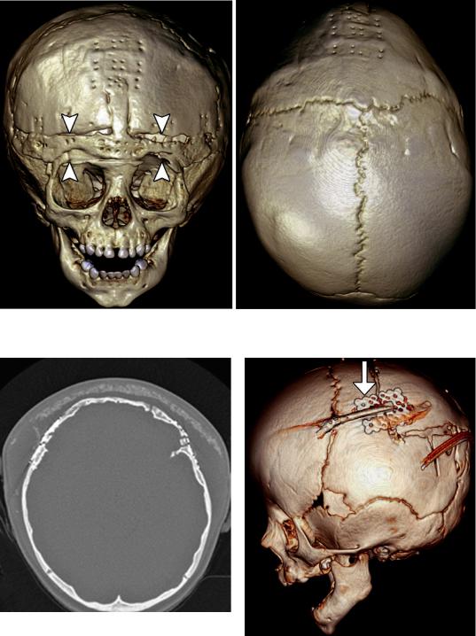
Correction cranioplasty and orbitofrontal advancement is a treatment option for trigonocephaly. This procedure generally entails take down of a bifrontal bone flap, removal of the orbital bandeau, followed by cranial vault reconstruction and advancement (Fig. 4.32). The use of reabsorbable fixation plate and screws yields superior cosmetic results and can appear as tiny bone defects without discernible radio-attenuating components otherwise on CT. The orbitofrontal advancement procedure can be augmented using onlay cements (Fig. 4.33). The incidence of complications is about 2%, and there is a 12% reoperation rate. Residual hypotelorism usually autocorrects, while bitemporal depressions may develop over time. High-resolution craniofacial CTs with 3D reformatted images are particularly useful for postoperative assessment and planning additional surgical intervention, if needed.
Management of raised intracranial pressure in syndromic multi-suture craniosynostosis by cranial vault expansion can be achieved by posterior calvarial vault expansion using distraction osteogenesis (Fig. 4.34).
Endoscopic craniosynostosis repair is a minimally invasive treatment option available to patients under 6 months of age. The technique consists of performing a strip craniectomy, whereby the affected suture is resected (suturectomy). This results in a linear gap along the course of the suture and allows the calvarium to be remodeled with postoperative helmet therapy (Fig. 4.35). Endoscopic-assisted wide-vertex craniectomy and barrel stave osteotomies can also be performed.
Calcium phosphate cement has been used to fill bony defects created during cranial remodeling surgery for craniosynostosis repair in the pediatric population and is intended to be osteoconductive. The bone cement initially has a putty-like consistency and can be applied in an inlay or onlay fashion. The material can undergo bioresorption and generally does not impede the actively growing calvarium. On CT, calcium phosphate cement appears as hyperattenuating with respect to bone (Fig. 4.36). The appearance of the junction between the native bone and the bone cement is variable, ranging from a sharp interface to a lucent gap when resorption occurs. The bone cement tends to be brittle and can also fragment. The presence of bone cement fragmentation does not necessarily imply palpable motility and is not particularly problematic if fragmentation occurs as an onlay.
4 Imaging the Postoperative Scalp and Cranium |
143 |
|
|
a |
b |
Fig. 4.31 Barrel stave osteotomies and cranial remodeling for scaphocephaly. Preoperative 3D CT image (a) shows dolichocephaly. Postoperative 3D CT image (b)
demonstrates multiple parietal barrel stave osteotomies, resulting in improved skull morphology
a |
b |
Fig. 4.32 Correction cranioplasty and orbitofrontal advancement. The patient has a history of nonsyndromic trigonocephaly. Preoperative frontal (a) and top view 3D CT (b) images show fusion of the metopic suture, with prominent frontal beaking. Postoperative frontal (c) and
top view 3D CT (d) images show osteotomies along the orbital bandeau (arrowheads). The multiple tiny holes in the calvarium correspond to the attachment sites of the absorbable plates, which are otherwise not visible
144 |
D.T. Ginat et al. |
|
|
c |
d |
Fig.4.32 (continued)
Fig. 4.33 Orbitofrontal advancement surgery with onlay cement. Axial CT image shows the hyperattenuating artificial bone cement superficial to the reconstructed frontal bone. The presence of seroma displaces the cement away from the surface of the calvarium and bifrontal craniotomies
Fig. 4.34 Posterior cranial vault distraction. Lateral 3D CT image of the skull shows parietal osteotomies with a distraction device in position (arrow)

4 Imaging the Postoperative Scalp and Cranium |
145 |
|
|
a |
b |
Fig. 4.35 Endoscopic strip craniectomy. Preoperative 3D CT image (a) shows asymmetric right coronal synostosis, resulting in deformity of the calvarium. Postoperative
3D CT image (b) shows interval resection of the right coronal suture (arrows), resulting in improved contours of the skull
Fig. 4.36 Calcium phosphate cement for craniosynostosis repair. 3D CT image shows several areas of the hyperattenuating cement used to fill the craniectomy defects