

02 BOPs / M02-040 - Liquid Process Piping - Part 5 - Valves - US
.pdfLiquid Process Piping - Part 5: Valves – M02-040
that will position the valve in the event of loss of air supply. These accessories include spring return, pneumatic trip valves, and lock-up type systems. It is common to include manual operators along with pneumatic piston operators in a design. These manual operators can then act as travel stops to limit either full opening or full closing of the valve.
Electric and electro-hydraulic operators are more expensive than pneumatic actuators; however, they offer advantages when no existing air supply source is available, where low ambient temperatures could affect pneumatic supply lines, or where very large stem forces or shaft forces are required. Electrical operators only require electrical power to the motors and electrical input signal from the controller in order to be positioned. Electrical operators are usually self-contained and operate within either a weather-proof or an explosion-proof casing.
An auxiliary positioner or booster is sometimes used on pneumatic operating systems when it is necessary to split the controller output to more than one valve, to amplify the controller above the standard range in order to provide increased actuator thrust, or to provide the best possible control with minimum overshoot and fastest possible recoveryfollowing a disturbance or load change. Determination of whether to use a positioner or a booster depends on the speed of the system response. If the system is relatively fast, such as is typical of pressure control and most flow control loops, the proper choice is a booster. If the system is relatively slow, as is typical of liquid level, blending, temperature and reactor control loads, the proper choice is a positioner1.
Hydraulic snubbers dampen the instability of the valve plug in severe applications and are used on pneumatic piston and direct acting diaphragm actuators.
Limit switches can be used to operate signal lights, solenoid valves, electric relays, or alarms. The limit switches are typically provided with 1 to 6 individual switches and are operated by the movement of the valve stem. It is common for each switch to be individually adjustable and used to indicate the full open or full closed position on a valve.
Electro-pneumatic transducers and electro-pneumatic positionersare used in electronic control loops to position pneumaticallyoperated control valves. The positioner or transducer receives a current input signal and then supplies a proportional pneumatic output signal to the pneumatic actuator to position the valve.
g. Supports
Specific pipe material design recommendations are followedwhen designing supports for valves. In general, onehanger or other support should be specified for each side of a valve, that is, along the two pipe sections immediately adjacent to the valve. The weight of the valveis included in the calculation of the maximum span of supports.
10-2. Valve Types
The main valve types have many variations and may have different names depending upon manufacturer. Careful selectionand detailed specifications are required to insure that design and performance requirements are met.
a. Check Valves
Checkvalves are self-actuated. These valves are opened, and sustained in the open position, by the force of the liquid velocity pressure. They are closed by the force of gravity or backflow. The seating load and tightness is dependent upon the amount of back pressure. Typical check valves include swing check, tilting disc check, lift check, and stop check. Other check valve types are available, however.
Swing check valves are used to prevent flow reversal in horizontalor vertical upward pipelines (vertical pipes or pipes in any angle from horizontal to vertical with upward flow only). Swing check valves have discs that swingopen and closed. The discs are typically designed to close on their own weight, and may be in a state of constantmovement if velocity pressure is not sufficient to hold the valve in a wide open position. Premature wear or noisy operation of the swing check valves can be avoidedby selecting the correct size on the basis of flow
1Fisher Control Company, p. 35.
10-9

Liquid Process Piping - Part 5: Valves – M02-040
conditions. The minimum velocity required to hold a swing check valve in the open position is expressed bythe empirical formula :
2
V ' j v
v
where:
V = liquid flow, m/s (ft/s)
v = specific volume of the liquid, m3/N (ft3/lb)
j= 133.7 (35) for Y-pattern
=229.1 (60) for bolted cap
=381.9 (100) for U/L listed
Tilting disc check valves are pivoted circular discs mounted in a cylindrical housing. These check valves have the ability to close rapidly, thereby minimizing slamming and vibrations. Tilting disc checks are used to prevent reversals in horizontal or vertical-up lines similar to swing check valves. The minimum velocity required for holding a tilting check valve wide open can be determined by the empirical formula3:
V ' j v
v
where:
V = liquid flow, m/s (ft/s)
v = specific volume of the liquid, m3/N (ft3/lb)
j = 305.5 (80) for a 5 disc angle (typical for steel) = 114.6 (30) for a 15 disc angle (typical for iron)
Lift check valves also operate automatically by line pressure. Theyare installed with pressure under the disc. A lift check valve typically has a disc that is free floating and is lifted by the flow. Liquid has an indirect line of flow, so the lift check is restricting the flow. Because of this, lift check valves are similar to globe valves and are generally used as a companion to globe valves. Lift check valves will only operate in horizontal lines. The minimum velocityrequired to hold a lift check valve open is calculated using the following empirical formula4:
V ' j$2 <
<
where:
V = liquid flow, m/s (ft/s)
v = specific volume of the liquid, m3/N (ft3/lb) j = 152.8 (40) for bolted cap
= 534.7 (140) for Y-pattern
$ = ratio of port diameter to inside pipe diameter
Stop check valves are typically used in high pressure and hazardous applications. Stop check valves have a floating disc. Sizing of these valves is extremely important because of the floating disc, and manufacturer's recommended procedures should be used. Stop check valves typically have a manual operator and, in this manner,can be forced closed to prevent any backflow of materials. The minimum velocity required for a full disc lift in a stop check valve is estimated by the following empirical formula5:
V ' j$2 <
<
where:
V = liquid flow, m/s (ft/s)
v = specific volume of the liquid, m3/N (ft3/lb) j = 210.0 (55) globe, OS&Y blocked bonnet
=286.4 (7S) angle, OS&Y blocked bonnet
=229.1 (60) Y-pattern, OS&Y bolted bonnet
=534.7 (140) Y-pattern, threaded bonnet
$ = ratio of port diameter to inside pipe diameter
Use of these empirical methods may result in a check valvesized smaller than the piping which is used. If this is the case, reducers are used to decrease pipe size to the smaller valve. The pressure drop is no greater than that ofthe larger valve that is partially open, and valve life is extended6.
2Crane Valves, Engineering Data, p. 53.
3Ibid., p. 53.
4Ibid., p. 53.
5Ibid., p. 54.
6Crane Valves, Cast Steel Valves, p. 14.
10-10

Liquid Process Piping - Part 5: Valves – M02-040
b. Ball Valves
Ball valves with standard materials are low cost, compact, lightweight, easy to install, and easy to operate. They offer full flow with minimum turbulence and can balance or throttle fluids. Typically, ball valves move from closed to full open in a quarter of a turn of the shaft and are, therefore, referred to as quarter turn ball valves. Low torque requirements can permit ball valves to be used in quick manual or automatic operation, and these valves have a long reliable service life. Ball valves can be full ball or other configurations such as V-port.
Full ball valves employ a complete sphere as the flow controlling member. They are of rotary shaft design and include a flow passage. There are many varieties of the full ball valves, and they can be trunion mounted with a single piece ball and shaft to reduce torque requirements and lost motion.
One of the most popular flow controlling members of the throttling-type ball valves is a V-port ball valve. A V-port ball valve utilizes a partial sphere that has a V- shaped notch in it. This notch permits a wide range of service and produces an equal percentage flow characteristic. The straight-forward flow design produces very little pressure drop, and the valve is suited to the control of erosive and viscous fluids or other services that have entrained solids or fibers. The V-port ball remains in contact with the seal, which produces a shearing effect as the ball closes, thus minimizing clogging.
c. Gate Valves
The gate valve is one of the most common valves used in liquid piping. This valve, as a rule, is an isolation valve used to turn on and shut off the flow, isolating either a piece of equipment or a pipeline, as opposed to actually regulating flow. The gate valve has a gate-like disc which operates at a right angle to the flow path. As such, it has a straight through port that results in minimum turbulence erosion and resistance to flow. However, because the gate or the seating is perpendicular to the flow, gate valves are impractical for throttling service and are not used for frequent operation applications.
Repeated closure of a gate valve, or rather movement toward closure of a gate valve, results in high velocity flow. This creates the threat of wire drawing and erosion of seating services. Many gate valves have wedge discs
with matching tapered seats. Therefore, the refacing or repairing of the seating surfaces is not a simple operation. Gate valves should not, therefore, be used frequently to avoidincreased maintenance costs. In addition, a slightly open gate valve can cause turbulent flow with vibrating and chattering of the disc.
A gate valve usually requires multiple turns of its hand wheel manual operator in order to be opened fully. The volume of flow through the valve is not in direct proportion to the number of turns of the hand wheel.
d. Globe and Angle Valves
Liquid flow does not pass straight through globe valves. Therefore,it causes an increased resistance to flow and a considerable pressure drop. Angle valves are similar to globe valves; however, the inlet and outlet ports are at 90 angles to one another, rather than at 180 angles. Because of this difference, the angle valves have slightly lessresistance to flow than globe valves. However, both valve types operate similarly in principle and, for the purposes of this document, discussion of globe valves will also pertain to angle valves.
Thereare a number of common globe valve seating types. Table 10-8 presents some of the more common seating types, along with advantages and disadvantages of each.
Theseating of the plug in a globe valve is parallel to the lineof liquid flow. Because of this seating arrangement, globe valves are very suitable for throttling flow with a minimal seat erosion or threat of wire drawing.
Aglobe valve opens in direct proportion to the number of turns of its actuator. This feature allows globe valves to closely regulate flow, even with manual operators. For example,if it takes four turns to open a globe valve fully, thenapproximately one turn of a hand wheel will release about 25% of the flow, two turns will release 50%, and three turns will release 75%. In addition, the shorter travel saves time and work, as well as wear on valve parts.
Maintenance is relatively easy with globe valves. The seats and discs are plugs, and most globe valves can be repaired without actually removing the valve from the pipe.
10-11

Liquid Process Piping - Part 5: Valves – M02-040
|
|
|
Table 10-8 |
|
Common Globe Valve Seating |
|
|
Type |
Comments |
|
|
Plug |
Long taper with matching seat provides wide seating contact area. |
|
Excellent for severe throttling applications. |
|
Resistant to leakage resulting from abrasion. |
|
With proper material selection, very effective for resisting erosion. |
Conventional Disc |
Narrow contact with seat. |
|
Good for normal service, but not for severe throttling applications. |
|
Subject to erosion and wire drawing. |
|
Good seating contact if uniform deposits (such as from coking actions) occur. |
|
Non-uniform deposits make tight closure difficult. |
Composition Disc |
“Soft” discs provided in different material combinations depending upon liquid |
|
service. |
|
Good for moderate pressure applications except for close throttling, which will |
|
rapidly erode the disc. |
Needle |
Sharp pointed disc with matching seat provides fine control of liquid flow in |
|
small-diameter piping. |
|
Stem threads are fine, so considerable stem movement is required to open or |
|
close. |
Source: Compiled by SAIC, 1998 |
|
|
|
e. Butterfly Valves |
f. Pinch Valves |
Butterfly valves provide a high capacity with low pressure loss and are durable, efficient, and reliable. The chief advantage of the butterfly valve is its seating surface. The reason for this advantage is that the disc impinges against a resilient liner and provides bubble tightness with very low operating torque. Butterfly valves exhibit an approximately equal percentage of flow characteristic and can be used for throttling service or for on/off control.
Typical butterfly bodies include a wafer design, a lug wafer design (a wafer with the addition of lugs around the bodies), and a flanged design. In all designs, butterfly valves are typicallymade with standard raised face piping flanges. Butterfly valves are available standard in sizes up to 72 inches for many different applications. The operators can be either pneumatic or electric.
Pinchvalves, as the name suggests, pinch an elastomeric sleeve shut in order to throttle the flow through the pipeline. Because of the streamlined flow path, the pinch valvehas verygood fluid capacity. Pinch valves typically have a fairly linear characteristic. However, some manufacturers offer field reversible cam-characterizable positioners. These positioners will vary the rate of stem change as a function of position in order to match the flowcharacteristics desired. In some instances, the cams are set up to provide an equal percentage flow characteristic through a pinch valve.
The pinch valve sleeve is available in various elastomer materials in order to adjust for chemical resistance. In addition, because the throttling takes place in the elastomersleeve, and elastomers typically have very good abrasion resistance; pinch valves are often used for slurries or liquids that contain high amounts of solids.
10-12

Liquid Process Piping - Part 5: Valves – M02-040
g. Plug Valves |
|
therequired flow. Control valves that are sized too large |
||||||||
|
|
|
or are arbitrarily sized to match the connecting pipe, will |
|||||||
Plug valves are another type of isolation valve designed |
resultin increased capital costs, decreased valve life (due |
|||||||||
for uses similar to those of gate valves, where quick |
to the throttling and erosion effects when operating near |
|||||||||
shutoff is required. They are not generally designed for |
to the closed position), and decreased performance (by |
|||||||||
flow regulation. Plug valves are sometimes also called |
limiting rangeability). |
Control valves are optimally |
||||||||
cock valves. They are typically a quarter turn open and |
selected by identifying the flow characteristic required, |
|||||||||
close. Plug valves have the capability of having multiple |
then calculating an expected flow coefficient and the |
|||||||||
outlet ports. This is advantageous in that it can simplify |
maximum allowable pressure drop. These factors are |
|||||||||
piping. |
Plug valves are available with inlet and outlet |
then compared to manufacturers' data for specific valve |
||||||||
ports with four-way multi-port valves which can be used |
types and sizes. |
|
|
|
|
|
|
|||
in place of two, three or four straight valves. |
|
|
|
|
|
|
|
|||
|
|
|
To select a control valve, the process application must be |
|||||||
h. Self-Contained Automatic Valves |
|
understood. Minimum information considered includes |
||||||||
|
|
|
desired flow characteristics; type, temperature, viscosity, |
|||||||
Self-contained automatic valves are used for pressure- |
and specific gravity of the liquid; minimum and |
|||||||||
reducing stations. The valve body itself is normally a |
maximum flow capacity; minimum and maximum valve |
|||||||||
globe-type valve. It is normally diaphragm actuated and |
inlet pressure; and minimum and maximum valve outlet |
|||||||||
hydraulically operated. The valves are |
capable of |
pressure. |
|
|
|
|
|
|
||
maintaining constant downstream pressure regardless of |
|
|
|
|
|
|
|
|||
the fluctuations in flow or upstream pressure by internal |
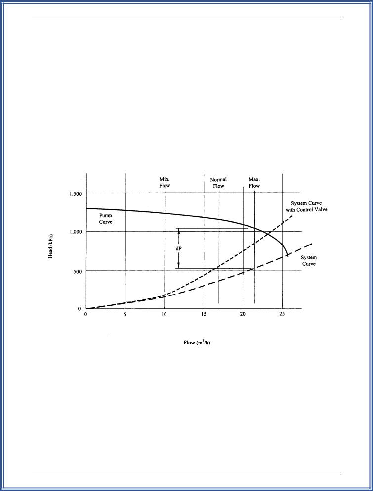
For example, Figure 10-2 depicts a piping system curve, |
|||||||||
hydraulic controllers. |
|
with and without the control valve, and an overlying |
||||||||
|
|
|
pump curve. Typically, a valve differential pressure ( P) |
|||||||
10-3. |
Valve Sizing and Selection |
|
ofapproximately 33% of the total piping system friction |
|||||||
|
|
|
drop at maximum flow is desired (as shown on Figure |
|||||||
Valve sizing and type selection is a critical component of |
10-2). For systems that require low turndown, or face |
|||||||||
a piping design. Valve type is shown on P&IDs, and |
abrasion or other problems, the valve P may be as low |
|||||||||
valve size is commonly provided on valve schedules. |
||||||||||
as 15%7. |
|
|
|
|
|
|
||||
The sizing and selection procedures are different for non- |
|
|
|
|
|
|
|
|||
control and control valves. |
|
Once a desired P is determined, the valve flow |
||||||||
|
|
|
||||||||
a. Non-Control Valves |
|
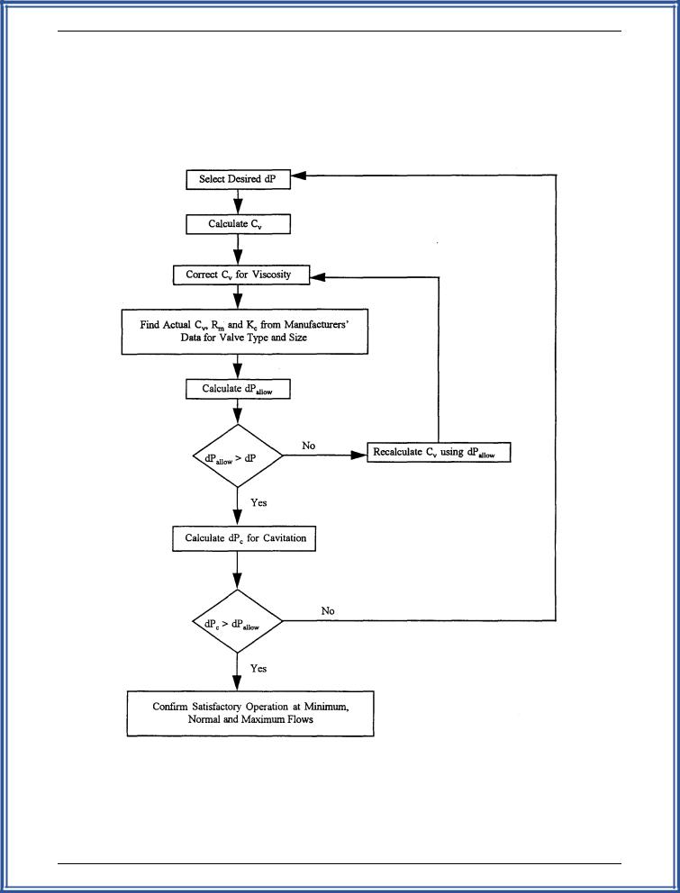
coefficient (Cv) and allowable pressure drop ( Pallow) are |
||||||||
|
calculated for a fully open valve in accordance with the |
|||||||||
|
|
|
||||||||
Non-control valves used for isolation are the same size as |
flow chart depicted on Figure 10-3. The valve recovery |
|||||||||
factor (Rm) and cavitation index (Kc) are determined from |
||||||||||
the connecting pipe. This sizing reduces pressure loss. |
||||||||||
Check valves may be smaller than the connecting pipe, |
manufacturers' data for a specific type and size of valve. |
|||||||||
|
|
|
|
|
|
|
||||
provided that the valves are properly sized to ensure full |
The sizing formulas for incompressible flow without |
|||||||||
open operation without flow restriction. |
Materials of |
|||||||||
mixed-phase fluids, dense slurries, dry solids or non- |
||||||||||
construction, wetted or otherwise, and end connections |
||||||||||
Newtonian liquids are as follows8: |
||||||||||
are in compliance with applicable codes and standards |
||||||||||
|
|
|
|
|
|
|
||||
and address the fluid application for corrosivity (see |
Cv |
' |
Q |
|
|
s.g. |
|
|||
|
|
|||||||||
|
|
|||||||||
Paragraph 10-1). |
|
|
|
|||||||
|
|
P |
||||||||
|
|
N1 |
||||||||
|
|
|
|
|
||||||
b. Control Valves |
|
where: |
|
|
|
|
|
|
||
|
|
|
|
|
|
|
|
|
||
Control valves are sized and selected |
to optimize |
C = valve flow coefficient |
|
|
||||||
v |
|
|
|
|
|
|
||||
application. Valves that are sized too small will not pass |
Q = flow, m3/hour (gpm) |
|
7Gardellin, p. 4.
8ISA-S75.01, pp. 15-18, 33-35.
10-13
Liquid Process Piping - Part 5: Valves – M02-040
Figure 10-2. Control Valve Pressure Drop Curve
(Source: SAIC, 1998)
10-14
Liquid Process Piping - Part 5: Valves – M02-040
Figure 10-3. Control Valve Sizing
(Source: SAIC, 1998)
10-15
Liquid Process Piping - Part 5: Valves – M02-040
N1 = Conversion factor, 0.085 when Q is in m3/hour and P is in kPa (1.00 when Q is in gpm and P is in psi)
s.g. = specific gravity of liquid
P = differential pressure across valve, kPa (psi)
|
N |
F Q |
|
|
R |
2 |
C |
2 |
|
1/4 |
|
|
|
|
|
||||||
Re ' |
4 |
d |
|
|
|
m |
|
v |
% 1 |
|
|
|
|
|
|
|
|
|
|
||
v |
|
|
|
|
|
|
|
|
|
|
|
< Rm1/2Cv1/2 |
|
|
N2 |
d4 |
|
||||
where:
Rev = valve Reynolds number
N4 = conversion factor, 76,000 when Q is in m3/hour and d is in mm (17,300 when Q is in gpm and d is in inches)
Fd = valve style modifier, see Table 10-9 Q = volumetric flow rate, m3/hour (gpm)
< = kinematic viscosity, mm2/sec (centistoke)
Rm = valve recoveryfactor, from manufacturers' data (see Table 10-9)
Cv = valve flow coefficient
N2 = conversion factor, 0.00214 when d is in mm (890 when d is in inches)
d = valve inlet diameter, mm (in)
C ' Cv
vc FR
where:
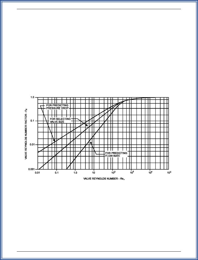
Cvc = valve flow coefficient corrected for viscosity FR = valve Reynolds number factor (see Figure 10-4)
Pallow ' Rm2 (Pi & rc Pv)
where:
Pallow = maximum valve P to avoid choked flow, kPa (psi)
Rm = valve recoveryfactor, from manufacturers' data (see Table 10-9)
Pi = valve inlet pressure, kPa (psi)
rc = critical pressure ratio, calculation as follows or see Figure 10-5
Pv = liquid vapor pressure, kPa (psia)
|
|
P |
1/2 |
|
rc |
' 0.96 & 0.28 |
v |
||
Pc |
||||
|
|
|||
where:
rc = critical pressure ratio
Pv = liquid vapor pressure, kPa (psi)
Pc = absolute thermodynamic critical pressure, kPa (psi)
)Pc ' Kc (Pi & Pv)
where:
Pc = valve P at which cavitation damage occurs, kPa (psi)
Kc = cavitation index, from manufacturers' data Pi = value inlet pressure, kPa (psi)
Pv = liquid vapor pressure, kPa (psi)
Example Problem 8:
Figure 10-2 represents the process to be controlled and controlvalve is for flow control purposes with an orifice plate flow measurement device. The liquid is water with trace hydrocarbons. The pipe size is 100 mm and the operating conditions are: T = 15.6 C; Pi = 517 kPa, 172.4 kPa, and 1030 kPa for normal, minimum, and maximum operating conditions, respectively.
Solution:
Step 1. From Figure 10-2, P at max. flow = 496 kPa and Q = 17 m3/hour normal
10 m3/hour minimum
21.5 m3/hour maximum
Step 2. The flow measurement device is proportional to flow squared so that an equal percentage for characteristic is desired. Assume a butterfly valve will be used so Fd = 0.7, and Rm = 0.7 (from Table 10-9)
Step 3. From common fluid mechanics reference materials:s.g. = 1.0; Pv = 1.85 kPa; Pc = 22.09 MPa; < = 1.13 mm2/sec.
Step 4. Therefore, the valve calculations are:
10-16

Liquid Process Piping - Part 5: Valves – M02-040
TABLE 10-9
Example Values of Valve Capacity Factors
Valve Type |
Trim Type |
Flow Direction* |
Rm |
Fd** |
Cv/d2*** |
|||
|
|
|
|
|
|
|
||
Globe |
Ported plug |
Either |
0.9 |
1.0 |
6,129 |
(9.5) |
||
- Single port |
|
|
|
|
|
|
|
|
Contoured plug |
Open |
0.9 |
1.0 |
7,098 |
(11) |
|||
|
||||||||
|
|
|
|
|
|
|
||
|
|
Close |
0.8 |
1.0 |
7,098 |
(11) |
||
|
|
|
|
|
|
|
||
|
Characterized cage |
Open |
0.9 |
1.0 |
9,032 |
(14) |
||
|
|
|
|
|
|
|
||
|
|
Close |
0.85 |
1.0 |
10,322 |
(16) |
||
|
|
|
|
|
|
|
||
|
Wing guided |
Either |
0.9 |
1.0 |
7,098 |
(11) |
||
|
|
|
|
|
|
|
||
- Double port |
Ported plug |
Either |
0.9 |
0.7 |
8,065 |
(12.5) |
||
|
|
|
|
|
|
|
||
|
Contoured plug |
Either |
0.85 |
0.7 |
8,387 |
(13) |
||
|
|
|
|
|
|
|
||
|
Wing guided |
Either |
0.9 |
0.7 |
9,032 |
(14) |
||
|
|
|
|
|
|
|
||
- Rotary |
Eccentric Spherical plug |
Open |
0.85 |
1.0 |
7,742 |
(12) |
||
|
|
|
|
|
|
|
||
|
|
Close |
0.68 |
1.0 |
8,710 |
(13.5) |
||
Angle |
Contoured plug |
Open |
0.9 |
1.0 |
10,968 |
(17) |
||
|
|
|
|
|
|
|
||
|
|
Close |
0.8 |
1.0 |
12,903 |
(20) |
||
|
|
|
|
|
|
|
||
|
Characterized cage |
Open |
0.85 |
1.0 |
7,742 |
(12) |
||
|
|
|
|
|
|
|
||
|
|
Close |
0.8 |
1.0 |
7,742 |
(12) |
||
|
|
|
|
|
|
|
||
|
Venturi |
Close |
0.5 |
1.0 |
14,194 |
(22) |
||
|
|
|
|
|
|
|
||
Ball |
Segmented |
Open |
0.6 |
1.0 |
16,129 |
(25) |
||
|
|
|
|
|
|
|
||
|
Standard port (diameter 0.8d) |
Either |
0.55 |
1.0 |
14,194 |
(22) |
||
|
|
|
|
|
|
|
||
Butterfly |
60-Degree aligned |
Either |
0.68 |
0.7 |
11,290 |
(17.5) |
||
|
|
|
|
|
|
|
||
|
Fluted vane |
Either |
0.7 |
0.7 |
16,129 |
(25) |
||
|
|
|
|
|
|
|
||
|
90-Degree offset seat |
Either |
0.60 |
0.7 |
18,710 |
(29) |
||
|
|
|
|
|
|
|
|
|
* |
Flow direction tends to open or close the valve: i.e., push the closure member away from or towards the seat. |
|
|
||
** |
In general, an F |
value of 1.0 can be used for valves with a single flow passage. An F value of 0.7 can be used |
|
d |
d |
|
for valves with two flow passages, such as double-ported globe valves and butterfly valves. |
|
*** |
In this table, d may be taken as the nominal valve size, mm (in). |
|
NOTE: The values are typical only for the types of valves shown at their rated travel for full-size trim. Significant variations in value may occur because of any of the following reasons: reduced travel, trim type, reduced port size, and valve manufacturer.
Source: ISA -S75.01, p. 31; Copyrighted material reprinted by permission of the Instrument Society of America, all rights reserved.
10-17
Liquid Process Piping - Part 5: Valves – M02-040
Figure 10-4. Valve Factor Diagram (Source: ISA-S75.01-1985 (R 1995), p. 34.)
10-18