02 BOPs / M02-040 - Liquid Process Piping - Part 5 - Valves - US
.pdf
Liquid Process Piping - Part 5: Valves – M02-040
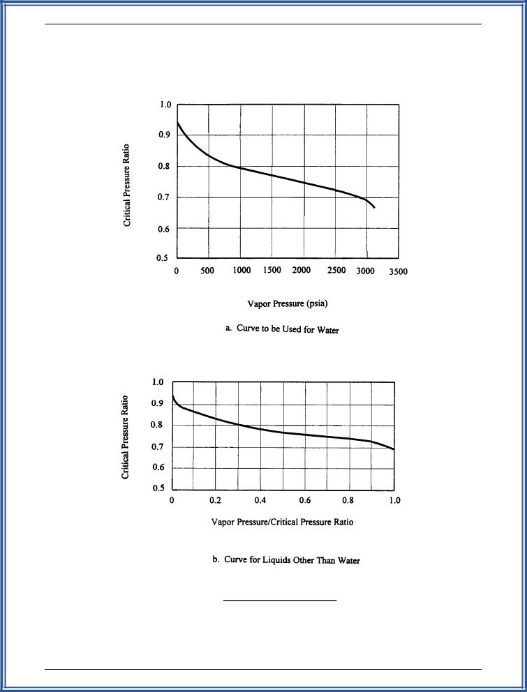
Figure 10-5. Critical Pressure Ratio
(Source: Fisher, Control Valve Handbook, 2nd Ed., p. 67)
10-19

Liquid Process Piping - Part 5: Valves – M02-040
|
|
|
|
C |
v |
' |
Q |
|
|
|
|
|
|
s.g. |
|
|
|
|
|
|
|||
|
|
|
|
|
|
|
|
|
|
|
|
|
|
||||||||||
|
|
|
|
N1 |
|
|
|
)P |
|
|
|
|
|
||||||||||
|
|
|
|
|
|
|
|
|
|
|
|
|
|
|
|||||||||
|
|
|
|
|
|
|
|
|
|
|
|
|
|
|
|
||||||||
|
|
|
|
21.5 m 3/hour |
|
|
|
|
|
|
|
|
|
|
|
|
|||||||
|
C |
v |
' |
|
|
|
|
1.0 |
'11.4 |
|
|
||||||||||||
|
|
|
|
|
|
|
|||||||||||||||||
|
0.085 |
|
|
|
|
|
|
496 kPa |
|
|
|||||||||||||
|
|
|
|
|
|
|
|
|
|
|
|
|
|
||||||||||
|
|
|
|
|
|
|
|
|
|
|
|
|
|
|
|||||||||
|
|
|
|
N |
|
F Q |
|
R |
2 |
C2 |
|
1/4 |
|
|
|||||||||
|
|
|
|
|
|
|
|
|
|||||||||||||||
|
|
|
|
|
|
|
|
|
|
|
|||||||||||||
|
|
Re ' |
4 |
d |
|
|
|
m |
v |
% 1 |
|
|
|
||||||||||
|
|
|
|
|
|
|
|
|
|
|
|
|
|
|
|
|
|||||||
|
|
|
v |
< Rm1/2CV1/2 |
|
|
N2 |
d4 |
|
|
|
|
|
||||||||||
|
|
|
|
|
|
|
|
|
|
1/4 |
|||||||||||||
|
(76,000)(0.7)(21.5) |
|
|
|
|
|
|
(0.7)2(11.4)2 |
|
||||||||||||||
|
|
|
|
|
|
|
|
||||||||||||||||
Re ' |
|
|
|
|
|
%1 |
|
||||||||||||||||
|
|
|
|
|
|||||||||||||||||||
v |
(1.13)(0.7)1/2(11.4)1/2 |
|
|
|
(0.00214)(100)4 |
|
|
||||||||||||||||
|
|
|
|
|
|||||||||||||||||||
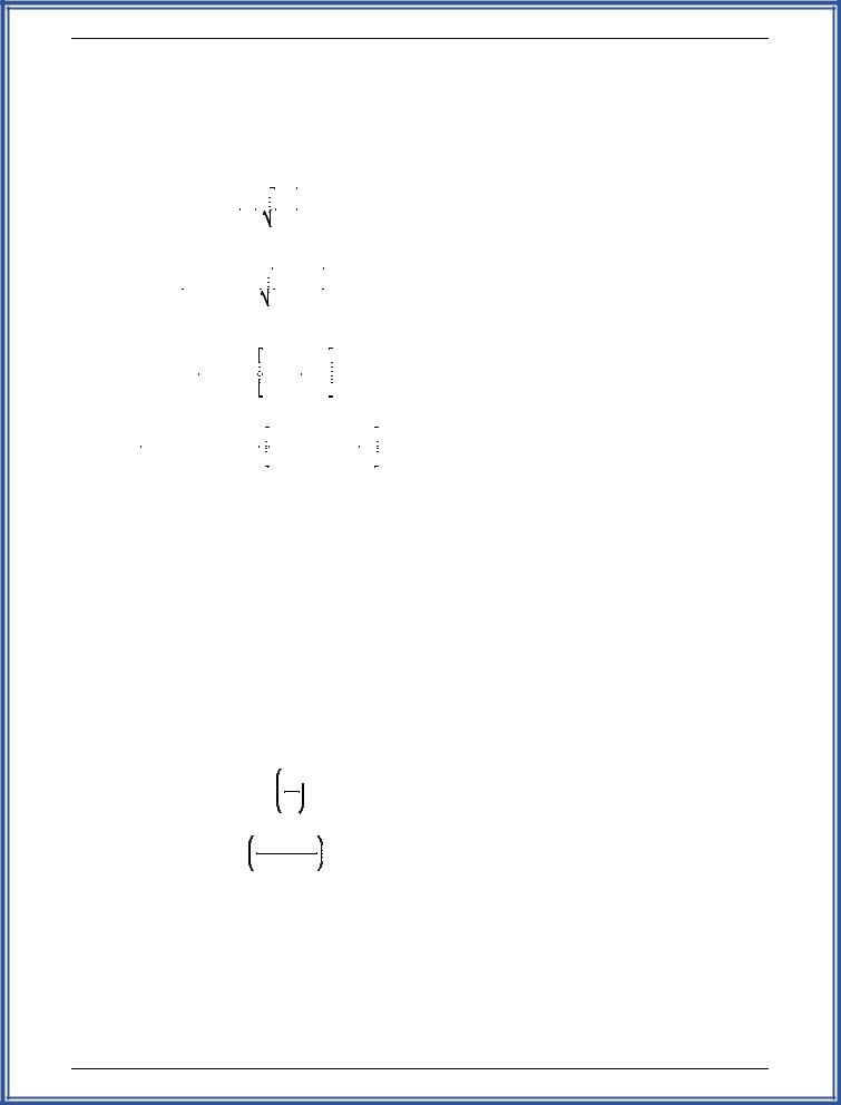
Rev ' 3.57 x 10⁵
FR = 1.0 from Figure 10-4 (a viscosity correction is not required due to the high Reynolds number).Therefore, Cvc = 11.4.
Step 5. From manufacturer's data, a 25 mm, 60 V-port ball valve at full open in a 50 mm pipe has a Cv of 11.2 and a Rm of 0.75. Therefore, neck the connecting piping down to 50 mm, and select a 25 mm V-port ball valve (has an equal percentage flow characteristic).
Step 6. The allowable pressure drop of the system is compared to the actual valve differential pressure to confirm that the valve will operate satisfactorily.
 1/2
1/2
rc ' 0.96 & 0.28  Pv
Pv
Pc
' 0.96 & 0.28 |
1.85kPa 1/2 |
|
22,090kPa rc ' 0.96
)Pallow ' Rm2 (Pi & rc Pv)
' (0.75)2[1030 kPa & (0.96)(1.85 kPa)]
)Pallow ' 578 kPa at max. flow (full open)
Pallow P at maximum flow, therefore, the valve is acceptable.
10-4. Valve Schedule
Manymanufacturers have PC-based sizing programs that will size and select their optimum valve for a specific application. In addition, computerized piping system design programs mayalso have valve sizing and selection routines that will select the optimum valve in their databases. Although these sizing programs can provide useful data, the optimum valve for a particular application may be found elsewhere. For design purposes, contract drawings include a valve schedule to aid in the bidding and proper supply of valves.
a. Valve Schedule
Table 10-10 presents a valve schedule that is included in the contract drawings for liquid process piping design.
b. Valve Operators Schedule
Table 10-11 is a valve operator schedule that is sometimes included in the contract drawings. This schedule is used when additional information, beyond that shown on a valve schedule, is required.
10-20

Table 10-10
Valve Schedule
|
Valve |
|
Size |
Flange |
Screwed |
Design |
Body |
Trim |
Bolting |
|
|
|
|
|
Tag/Ref |
Description |
Range |
Rating |
Ends |
Rating |
Materials |
Materials |
Materials |
Operation |
Service |
Remarks |
|
|
|
|
|
|
|
|
|
|
|
|
|
|
|
|
|
|
|
|
|
|
|
|
|
|
|
|
|
|
V120 |
Ball Valve, Full Port |
50 mm & |
- - |
Taper |
1.39 MPa |
316 SS |
316 SS Ball & Stem |
- - |
Lever |
IWW, SLG, |
|
|
|
|
Positive Shut-off |
Smaller |
|
ANSI B2.1 |
|
|
Glass Filled TFE |
|
|
WPS |
|
|
|
|
|
|
|
|
|
|
Seats, TFE Seals |
|
|
|
|
|
|
|
|
|
|
|
|
|
|
|
|
|
|
|
|
V121 |
Ball Valve, Full Port |
80 mm |
ANSI B16.5 |
- - |
689 kPa |
316 SS |
316 SS Ball & Stem |
CS |
Lever |
SW, ALT, |
Instrument Isolation |
|
|
|
Positive Shut-off |
|
Class 150 |
|
|
|
Glass Filled TFE |
ASTMA 307 |
|
RO, AL, |
Valves Only |
|
|
|
|
|
|
|
|
|
Seats, TFE Seals |
Gr B |
|
SWW, RL |
|
|
|
|
|
|
|
|
|
|
|
|
|
|
|
|
|
V122 |
Ball Valve, Full Port |
40 mm & |
ANSI B16.5 |
- - |
1.03 MPa |
316 SS |
316 SS Ball & Stem |
CS |
Lever |
WCR |
|
|
|
|
Positive Shut-off |
Smaller |
Class 300 |
|
|
|
Glass Filled TFE |
ASTMA 307 |
|
|
|
|
|
|
|
|
|
|
|
|
Seats, TFE Seals |
Gr B |
|
|
|
|
|
|
|
|
|
|
|
|
|
|
|
|
|
|
|
V123 |
Solid Wedge Gate Valve |
50 mm & |
ANSI B16.5 |
- - |
1.03 MPa |
CS |
13% Cr Steel Seats & |
CS |
Handwheel |
SLP |
|
|
|
|
O.S. & Y., Rising Stem |
Larger |
Class 300 |
|
|
ASTMA 216 |
SS Stem |
ASTMA 307 |
|
|
|
|
|
|
|
|
|
|
|
GR WCB |
|
Gr B |
|
|
|
|
|
|
|
|
|
|
|
|
|
|
|
|
|
|
|
V124 |
Double Disc Gate Valve |
50 mm & |
ANSI B16.5 |
- - |
689 kPa |
CS |
UT Trim |
CS |
Handwheel |
SL |
|
|
|
|
O.S. & Y., Rising Stem |
Larger |
Class 150 |
|
|
ASTMA 216 |
316 SS Stem |
ASTMA 307 |
|
|
|
|
|
|
|
|
|
|
|
GR WCB |
|
Gr B |
|
|
|
|
|
|
|
|
|
|
|
|
|
|
|
|
|
|
|
V150 |
Swing Check Valve |
50 mm to |
ANSI B16.5 |
- - |
689 kPa |
CS |
13% Cr Steel Seats & |
CS |
- - |
XLT, ALT, |
All Drain Points to be |
|
|
|
|
300 mm |
Class 150 |
|
|
ASTMA 216 |
Disc |
ASTMA 307 |
|
RL, AL, |
Threaded & Plugged |
|
|
|
|
|
|
|
|
GR WCB |
|
Gr B |
|
SLO, PLO |
|
|
|
|
|
|
|
|
|
|
|
|
|
|
|
|
|
V151 |
Swing Check Valve |
50 mm & |
- - |
Taper |
1.39 MPa |
Bronze |
Bronze |
- - |
- - |
PW |
All Drain Points to be |
|
|
|
|
Smaller |
|
ANSI B2.1 |
|
|
|
|
|
|
Threaded & Plugged |
|
|
|
|
|
|
|
|
|
|
|
|
|
|
|
|
V152 |
Y-Pattern Check Valve |
50 mm & |
- - |
Socket |
17.2 MPa |
CS |
13% Cr Steel Seats & |
- - |
- - |
FWH |
|
|
|
|
|
Smaller |
|
Weld |
|
ASTMA 105 |
302 SS Spring |
|
|
|
|
|
|
|
|
|
|
|
|
|
|
|
|
|
|
|
|
V153 |
Lined Wafer Check Valve |
250 mm |
Fit |
- - |
689 kPa |
PFA Coated |
PFA Coated Steel |
- - |
- - |
DWH |
|
|
|
|
|
|
Between |
|
|
CS |
|
|
|
|
|
|
|
|
|
|
Class 150 |
|
|
|
|
|
|
|
|
|
|
|
|
|
|
|
|
|
|
|
|
|
|
|
|
V154 |
Wafer Style Check Valve |
100 mm |
Fit |
- - |
689 kPa |
410 SS |
302 SS |
- - |
- - |
AP |
All Drain Points to be |
|
|
|
|
to |
Between |
|
|
ASTMA 276 |
|
|
|
|
Threaded & Plugged |
|
|
|
|
250 mm |
Class 150 |
|
|
|
|
|
|
|
|
|
|
|
|
|
|
|
|
|
|
|
|
|
|
|
|
PCV-452 |
Globe Valve, Bolted |
100 mm |
ANSI B16.5 |
- - |
689 kPa |
CS |
SS |
CS |
Pneumatic |
RCY |
|
|
|
|
Bonnet, |
|
Class 150 |
|
|
ASTMA 216 |
|
ASTMA 307 |
Diaphragm |
|
|
|
|
|
O.S. & Y., Rising Stem |
|
|
|
|
GR WCB |
|
Gr B |
R.A. |
|
|
|
|
|
|
|
|
|
|
|
|
|
|
|
|
|
|
FCV-501 |
Butterfly Valve |
100 mm |
Fit |
- - |
689 kPa |
PFA Lined |
PFA Lined D.I. & SS |
- - |
Electric |
AG, AV |
|
|
|
|
|
|
Between |
|
|
D.I. |
Stem |
|
|
|
|
|
|
|
|
|
Class 150 |
|
|
|
|
|
|
|
|
|
|
|
|
|
|
|
|
|
|
|
|
|
|
|
|
FCV-625 |
Butterfly Valve |
300 mm |
Fit |
- - |
689 kPa |
PFTE Lined |
PTFE Lined CS & |
- - |
Electric, |
DWH |
|
|
|
|
|
|
Between |
|
|
CS |
SS Stem |
|
Enclosed |
|
|
|
|
|
|
|
Class 150 |
|
|
|
|
|
Gear |
|
|
|
|
|
|
|
|
|
|
|
|
|
|
|
|
|
Source: Example Schedule by SAIC, 1998.
21-10

 040-M02 – Valves 5: Part - Piping Process Liquid

Table 10-11
Valve Operator Schedule
|
Operator |
|
|
Maximum |
Electrical |
|
Materials of |
Failure |
Enclosure |
|
Associated |
|
|
|
Tag/Ref |
Description |
Type |
Air Pressure |
Supply |
Action |
Construction |
Mode |
Rating |
Accessories |
Valve |
Remarks |
|
|
|
|
|
|
|
|
|
|
|
|
|
|
|
|
|
|
|
|
|
|
|
|
|
|
|
|
|
|
V120 |
Ball Valve, Full Port |
Pneumatic, |
103 kPa |
- - |
R.A |
Manufacturer’ s |
F.O. |
Weather |
Positioner, |
PCV-452 |
|
|
|
|
Positive Shut-off |
Diaphragm |
|
|
|
Standard with Epoxy |
|
Proof |
Filter/Regulator, |
|
|
|
|
|
|
|
|
|
|
Coating |
|
|
Handwheel |
|
|
|
|
|
|
|
|
|
|
|
|
|
|
|
|
|
|
V121 |
Ball Valve, Full Port |
Pneumatic, |
1.03 MPa |
- - |
D.A. |
Manufacturer’ s |
F.C. |
Weather |
Positioner, |
PCV-1013 |
|
|
|
|
Positive Shut-off |
Piston |
|
|
|
Standard with Epoxy |
|
Proof |
Filter, |
|
|
|
|
|
|
|
|
|
|
Coating |
|
|
Handwheel |
|
|
|
|
|
|
|
|
|
|
|
|
|
|
|
|
|
|
V122 |
Ball Valve, Full Port |
Pneumatic, |
1.03 MPa |
- - |
D.A. |
Aluminum |
F.L. |
NEMA 4 |
I/P, Filter |
FCV-485 |
|
|
|
|
Positive Shut-off |
Rotary |
|
|
|
|
|
|
|
|
|
|
|
|
|
|
|
|
|
|
|
|
|
|
|
|
|
V123 |
Solid Wedge Gate Valve |
Electric, |
- - |
120 V, |
D.A. |
Manufacturer’ s |
F.L. |
NEMA 4 |
|
FCV-501 |
|
|
|
|
O.S. & Y., Rising Stem |
Rotary |
|
20 A, |
|
Standard with Epoxy |
|
|
|
|
|
|
|
|
|
|
|
1 ph |
|
Coating |
|
|
|
|
|
|
|
|
|
|
|
|
|
|
|
|
|
|
|
|
|
V124 |
Double Disc Gate Valve |
Electric, |
- - |
120 V, |
D.A. |
Manufacturer’ s |
F.C. |
NEMA 4X |
Enclosed Gear, |
FCV-625 |
|
|
|
|
O.S. & Y., Rising Stem |
Rotary |
|
20 A, |
|
Standard |
|
|
|
|
|
|
|
|
|
|
|
1 ph |
|
|
|
|
|
|
|
|
|
|
|
|
|
|
|
|
|
|
|
|
|
|
|
|
|
|
|
|
|
|
|
|
|
|
|
|
|
|
|
|
|
|
|
|
|
|
|
|
|
|
|
|
|
|
|
|
|
|
|
|
|
|
|
|
|
|
|
|
|
|
|
|
|
|
|
|
|
|
|
|
|
|
|
|
|
|
|
|
|
|
|
|
|
|
|
|
|
|
|
|
|
|
|
|
|
|
|
|
|
|
|
|
|
|
|
|
|
|
|
|
|
|
|
|
|
|
|
|
|
|
|
|
|
|
|
Source: Example Schedule by SAIC, 1998. |
|
|
|
|
|
|
|
|
|
|
|
|
|
|
|
|
|
|
|
|
|
|
|
|
|
|
22-10

 040-M02 – Valves 5: Part - Piping Process Liquid
