

L3 / 01_Свободная_Балка
.pdfShear and Bending Moment
Preprocessing
Enter the values into the table as shown at the right.
> OK
Close the Real Constants window.
> Close
The material properties for the Beam3 element need to be defined.
>Preprocessor > Material Props
>Material Models
The Define Material Models Behavior window should now be open.
We will use isotropic, linearly, elastic, structural properties.
Select the following from the Material
Models Available window:
>Structural > Linear > Elastic
>Isotropic
The window titled Linear Isotropic Properties for Material Number 1 now appears.
Enter 30e6 for EX (Young's Modulus) and
0.3for PRXY (Poission’s Ratio).
>OK
Close the Define Material Model Behavior window.
> Material > Exit
11

Shear and Bending Moment
Preprocessing
The next step is to define the keypoints (KP’s) that will help you build the rest of your model:
>Preprocessing > Modeling
>Create > Keypoints > In Active CS
The Create Keypoints in Active CS window will now appear. Here the KP’s will be given numbers and their respective (XYZ) coordinates.
Enter the KP numbers and coordinates that will correctly define the beam. Select Apply after each KP has been defined.
Note: Be sure to change the keypoint number every time you click apply to finish adding a keypoint. If
you don’t it will replace the last keypoint you entered with the new coordinates you just entered.
KP # 1: X=0, Y=0, Z=0
KP # 2: X=2, Y=0, Z=0
KP # 3: X=4, Y=0, Z=0
KP # 4: X=6, Y=0, Z=0
KP # 5: X=10, Y=0, Z=0
Select OK when complete.
In case you make a mistake in creating the keypoints, select:
>Preprocessing > Modeling
>Delete > Keypoints
Select the incorrect KP’s and select OK.
Your screen should look similar to the example below.
12

Shear and Bending Moment
Preprocessing
At times it will be helpful to turn on the keypoint numbers.
> PlotCtrls > Numbering > put a checkmark next to keypoint numbers > OK
Other numbers (for lines, areas, etc..) can be turned on in a similar manner.
At times it will also be helpful to have a list of keypoints (or nodes, lines, elements, loads, etc.). To generate a list of keypoints:
>List > Keypoint
>Coordinates Only
A list similar to the one to the right should appear.
13

Shear and Bending Moment
Preprocessing
The next step is to create lines between the
KP’s.
>Preprocessing > Modeling
>Create > Lines > Lines
>Straight Lines
The Create Straight Lines window should appear. You will create 4 lines. Create line 1 between the first two keypoints.
For line 1: MB1 KP1 then MB1 KP 2.
The other lines will be created in a similar manner.
For line 2: MB1 KP2 then MB1 KP 3.
For line 3: MB1 KP3 then MB1 KP 4.
For line 4: MB1 KP4 then MB1 KP 5.
Verify that each line only goes between the specified keypoints. When you are done creating the lines click ok in the Create Straight Lines window.
> OK
If you make a mistake, use the following steps to delete the lines:
>Preprocessing > Modeling
>Delete > Lines Only
You should now have something similar to the image shown below.
14

Shear and Bending Moment
Preprocessing
Now that the model has been created, it needs to be meshed. Models must be meshed before they can be solved. Models are meshed with elements.
First, the element size needs to be specified.
>Preprocessing > Meshing
>Size Cntrls > Manual Size
>Lines > All Lines
The Element Sizes on All Selected Lines window should appear. From this window, the number of divisions per element can be defined and also the element edge length.
Enter 0.1 into the Element edge length field.
> OK
Note: you could change the element edge length after completing the tutorial to a different value and rerun the solution to see how it affects the results.
With the mesh parameters complete, the lines representing the beam can now be meshed. Select:
>Preprocessing > Meshing > Mesh
>Lines
From the Mesh Lines window select Pick All.
> Pick all
Selecting Pick all will mesh all of the line segments that have been created.
The meshed line should appear similar to the one shown below. This completes the preprocessing phase.
15

Shear and Bending Moment
Solution
We will now move into the solution phase.
Before applying the loads and constraints to the beam, we will select to start a new analysis:
>Solution > Analysis Type
>New Analysis
For Type of Analysis select Static and select
OK.
The way this problem is setup, no constraints need to be added. Other problems which ask you to find shear and bending moment diagrams may require the use of constraints.
The forces and moments will now be added. It will be easier to select the keypoints (the locations of the forces and moments) if the keypoint numbers are turned on as previously explained. However, the current view probably shows just the elements and not the keypoints. You can see both the elements and the keypoints on the screen by selecting:
> Plot > Multiplots
To see just the keypoints;
> Plot > Keypoints > Keypoints
Use the plot menu to view your model in the way that will make it easier to complete each step in tutorial.
16
Shear and Bending Moment
Solution
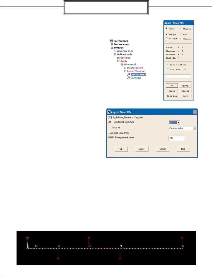
The loads will now be applied to the beam.
>Solutions > Define Loads > Apply
>Structural > Force/Moment
>On Keypoints
The Apply F/M on KPs window should now appear.
Select KP1 (hint it might be hidden behind the symbol for the coordinate system) and select OK.
In the Apply F/M on KPs window that now appears change the direction to of the force to FY and give it a value of 400.
> Apply
Repeat these same steps to apply the rest of the forces and moments. Moments are applied in the same way except that in the
Apply F/M on KPs window MZ is chosen as the direction. Select Apply after each one you create and close the window when you are done creating all of the them.
Location |
Direction |
Value |
KP1 |
MZ |
400 |
KP2 |
FY |
-400 |
KP2 |
MZ |
-400 |
KP3 |
FY |
200 |
KP4 |
FY |
-200 |
KP5 |
FY |
400 |
When you are done, your screen should look similar to the picture below.
17

Shear and Bending Moment
Solution
The distributed loads will now be applied to the beam.
>Solutions > Define Loads > Apply
>Structural > Pressure > On Beams
The Apply PRES on Beams window should appear.
Select all the elements between keypoints 2 and 3 (there should be 20 in all).
> Apply
The expanded Apply Pressure on Beams window should appear. From this window the direction of the pressure and its magnitude can be specified.
Enter 100 in the Pressure at Node I value field which will apply the pressure over the beam from keypoints 2 to 3. A positive entry in this field is defined as a downward pressure.
> OK
The first distributed load now appears on the model.
18

Shear and Bending Moment
Solution
Add the other two distributed load in a similar manner. Use the same commands as shown, but with the following changes:
For the second distributed load select all of the elements between KP3 and KP4 (should be 20 of them). Set the value at node I to be -100 (this will make the load act upward).
> OK
For the third distributed load select all of the elements between KP4 and KP5 (should be 40 of them). Set the value at node I to be 100.
> OK
The model is now completed.
19

Shear and Bending Moment
Solution
If you wish to view a 3D picture of your model select
>Plot Controls > Style
>Size and Shape
The Size and Shape window opens. Click the check box next to Display of Element to turn on the 3D image.
> OK
Now when you rotate your model using CTRL + MB3 , the model should appear to be 3D. You should see something similar to the image below.
You are now ready to solve the model.
20