


Chapter 9 - Encoders, Transducers, and Advanced Sensors
sealed to the end of a small tube or pipe. The two coils are connected to an AC Wheatstone bridge with two other matched coils L3 and L4. If the pressure inside the pipe is one atmosphere, the disk will be flat and the inductance of each of the two coils will be the same (L1=L2). In this case, the bridge will be balanced and Vout will be zero. If there is pressure inside the pipe, the diaphragm will deform (bulge) upward. Since the disk is made of a ferrous material, and since it has moved closer to L1, the reluctance in coil L1 will decrease which will increase its inductance. At the same time, since the disk has moved away from L2, its reluctance will increase which will decrease its inductance. This will unbalance the bridge and produce an AC output. The magnitude of the output is proportional to the displacement of the disk (the pressure), and the phase of the output with respect to the AC source depends on the direction of displacement (pressure or vacuum).
L1 |
L3 |
Ferrous
Diaphragm 
Vout
Seal
L2
L4
Pipe Wall
Figure 9-17 - Variable Reluctance Pressure Sensor
(Cross Section)
9-7. Flow
The flow, Q, of a fluid in a pipe is directly proportional to the velocity of the fluid, V, and the cross sectional area of the pipe, A. Therefore, we can say Q = V x A. This is a relatively simple concept to memorize by applying dimensional analysis. For example, in English units, flow is measured in cubic feet per second, velocity in feet per second, and area in square feet, which results in ft3/s = ft/s x ft2. Therefore, we may conclude that if we wish to increase the flow of a fluid in a pipe, we have two choices - we can increase the fluid’s velocity, or install a larger diameter pipe. Fluid flow is measured in many different ways, some (but not all) of which are discussed below. For a comprehensive treatment of fluid flow measurement techniques, the reader should refer to any manufacturer’s tutorial on the subject, such as Omega Instruments’ Fluid Flow and Level Handbook.
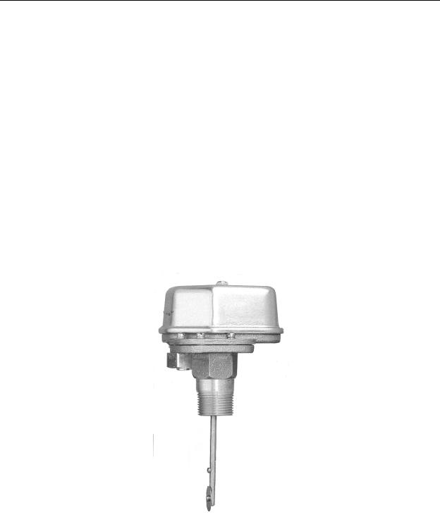
Drag Disk Flow Switch
9-18
Chapter 9 - Encoders, Transducers, and Advanced Sensors
Any time a moving fluid passes an obstruction, a pressure difference is created, with the higher pressure on the upstream side of the obstruction. This pressure difference applies a force to the obstruction that tends to move it in the direction of the fluid flow. The amount of force applied is proportional to the velocity of the fluid (which is proportional to flow rate), and the cross sectional area the obstruction presents to the flow. For example, a sailboat will move faster if either the wind velocity increases or if we turn the sails so that they present a larger area to the wind. We can take advantage of this force to actuate a switch by using a drag disk as shown Figure 9-18. This unit consists of a case containing a snap-action switch, a switch lever arm extending from the bottom of the case, and a circular disk attached to the end of the lever arm. In this case, the device is threaded into a “T” connector installed in the pipe and oriented such that the drag disk is perpendicular to the direction of flow. As flow rate increases it increases the force on the drag disk. At a predetermined high flow rate the force on the drag disk is sufficient to push the lever arm to the right and actuate the switch.
The trip point of this type of switch is adjustable by a screw adjustment that varies the counteracting spring force applied to the lever arm. In addition, the range of adjustment can be changed by changing the cross sectional area of the drag disk. Switches of this type are usually provided with a set of several drag disks of different sizes.
Figure 9-18 - Drag Disk
Flow Switch
(Omega Instruments)
9-19
Chapter 9 - Encoders, Transducers, and Advanced Sensors
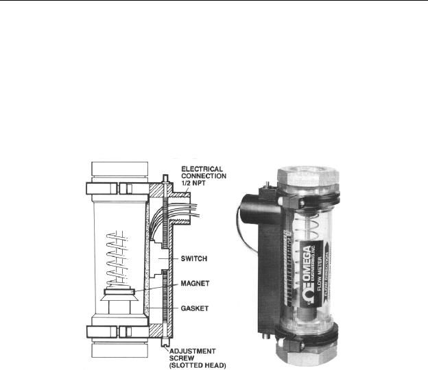
Another variation of the drag disk flow switch is the in-line flow meter with proximity switch. As shown in Figure 9-19 this device has it’s drag disk mounted inside a plastic or glass tube with an internal spring to counteract the force applied to the disk by fluid flow. Since the tube is clear and has graduations marked on the outside, the flow rate may also be visually measured by viewing the position of the drag disk inside the tube. A toroidal permanent magnet is mounted on the downstream side of the drag disk and is held in place by the spring force. A magnetic reed switch is mounted on the outside of the tube with it’s vertical position on the tube being set by an adjustment screw. As fluid flow increases the disk and piggy-back magnet will rise in the tube. When the magnet aligns with the reed switch the switch will actuate.
Figure 9-19 - In-Line Flow Meter with Proximity
Switch
(Omega Instruments)
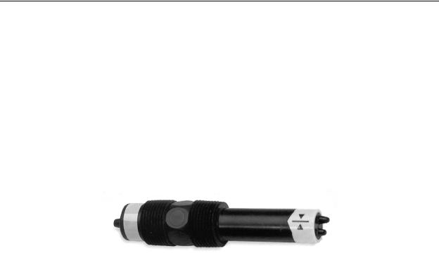
Thermal Dispersion Flow Switch
A method to indirectly measure flow is by measuring the amount of heat that the flow carries away from a heater element that is inserted into the flow. By setting a trip point, we can have an electronic temperature switch actuate when the temperature of the heated probe drops below a predetermined level. This device is called a thermal dispersion flow switch. One problem associated with this technique is that, since we may not know the temperature of the fluid in the pipe, it is difficult to determine the flow based simply on the temperature of the heated probe. For example, if we heat the probe to say 50 degrees
9-20
Chapter 9 - Encoders, Transducers, and Advanced Sensors
Celsius, and the fluid temperature happens to be 49 degrees Celsius, then when fluid is moving in the pipe our device will “see” a very slight temperature drop in the heated probe and therefore conclude that the flow is for all practical purposes zero. To circumvent this problem, this device actually consists of two probes, as shown in Figure 9-20. One probe is heated, one is not. The probe that is not heated will measure the static temperature of the fluid while the heated probe will measure the temperature decrease due to fluid flow. Electronic circuitry then calculates the temperature differential ratio, compares it to the setpoint (which is adjustable using a built-in potentiometer), and outputs a logical on/off signal. One major advantage to this type of temperature switch is that, since it has no moving parts, it is extremely reliable and it works well in dirty fluids that would normally foul the types of probes that have moving parts. Obviously, in dirty fluid systems, the probe must be periodically removed and cleaned in order to keep the setpoint from drifting due to contaminated probes.
Figure 9-20 - Thermal Dispersion Flow Switch
(Omega Instruments)
Paddlewheel Flow Sensor
One method to directly measure flow velocity is to simply insert a paddlewheel into the fluid flow and measure the speed that the paddlewheel rotates. This device, called a paddlewheel flow sensor (shown in Figure 9-21), usually provides an output of pulses, with the pulse rate being proportional to flow velocity. Some of the more elaborate models will also convert the pulse rate to a DC voltage (an analog output). Keep in mind that as with many types of flow sensors, the device actually measures fluid speed, not flow rate. However, flow rate can be calculated if the pipe diameter is also known.
9-21

Chapter 9 - Encoders, Transducers, and Advanced Sensors
Figure 9-21 - Paddle Wheel Flow Sensor
(Omega Instruments)
Turbine Flow Sensor
A variation on the paddlewheel sensor is the turbine flow sensor, illustrated in
Figure 9-22. In this case, the paddlewheel is replaced by a small turbine that is suspended in the pipe. A special support mechanism routes fluid through the vanes of the turbine without disturbing the flow (i.e. without causing turbulence). The turbine vanes are made of metal (usually brass); therefore they can be detected by an inductive proximity sensor which is mounted in the top of the unit. As with the paddlewheel, this device outputs a pulse train with the pulse frequency proportional to the flow velocity.
9-22

Chapter 9 - Encoders, Transducers, and Advanced Sensors
Figure 9-22 - Turbine Flow Sensor, Cut Away View
(Omega Instruments)
Pitot Tube Flow Sensor
As mentioned earlier, whenever an obstruction is placed within a fluid flow, a pressure difference occurs on the upstream and downstream sides of the obstruction that changes with the fluid flow velocity. This, of course, is the principle behind the operation of the drag disk, paddlewheel, and turbine sensors. This differential pressure is proportional to the square of the flow velocity. If we insert an obstruction into the fluid flow and measure the upstream and downstream pressures, we can calculate the fluid velocity.
The device that does this is called a pitot tube. The most common application for the pitot tube is in the sensor for airspeed indicators in aircraft. However, for measuring the flow velocity in a pipe, although the principle is the same as that of airspeed indicators, the pitot tube is constructed quite differently. The tube, shown in Figure 9-23, is constructed with two orifices, one to sense the upstream pressure and the other for downstream pressure. Two small pipes contained inside the pitot tube connect these two orifices to two valves on the opposite end of the probe. Two tubes connect the valves on the pitot tube to a differential pressure transducer that has an electrical analog output. In operation, the upstream and downstream pressures are sent from the pitot tube, through the valves, to the differential pressure transducer. Most manufacturers provide additional electrical circuitry inside the differential pressure transducer that will linearize and calibrate the analog output to be directly proportional to the fluid flow rate.
9-23