

Microcontrollers in Practice (Mitescu M., 2005)
.pdf
|
7.7 Exercises on Programming the A/D Converter AT90S8535 |
101 |
||
Table 7.3. The effect of programming [ADPS2:ADPS1:ADPS0] |
|
|||
|
|
|
|
|
|
[ADPS2:ADPS1:ADPS0] |
ADC clock is XTAL divided by: |
|
|
|
|
|
|
|
000 |
2 |
|
|
|
001 |
2 |
|
|
|
010 |
4 |
|
|
|
011 |
8 |
|
|
|
100 |
16 |
|
|
|
101 |
32 |
|
|
|
110 |
64 |
|
|
|
111 |
128 |
|
|
|
|
|
|
|
|
•[ADPS2:ADPS1:ADPS0] – AD Prescaller Select. The clock applied to the ADC subsystem is obtained by dividing the system clock using a prescaler.
These bits select the prescaler dividing rate according to Table 7.3.
The selection of the input upon which the conversion is executed is made by the ADMUX register. This has only three bits implemented, in the least significant positions.
ADMUX |
7 |
6 |
5 |
4 |
3 |
2 |
1 |
0 |
|
– |
– |
– |
– |
– |
MUX2 |
MUX1 |
MUX0 |
|
|
|
|
|
|
|
|
|
RESET |
0 |
0 |
0 |
0 |
0 |
0 |
0 |
0 |
[MUX2:MUX1:MUX0] Analog multiplexer selection bits. These bits instruct the analog multiplexer to select the input to be converted. [0:0:0] corresponds to ADC0, and so on; [1:1:1] selects ADC7.
Important note. The analog inputs of AT90S8535 use the I/O lines of PORTA. In principle, some of the A port lines can be configured as output lines. However, it is not recommended to activate these output lines while a conversion is in progress, because conversion errors can occur.
7.7 Exercises on Programming the A/D Converter AT90S8535
SX 7.4
Write the initialization sequence to select the ADC to operate using the clock frequency XTAL/2, in single conversion mode, with the interrupts enabled.
Solution
The control word to be written in ADCSR must contain the bits ADEN, ADIE and ADPS2 set to 1, the remaining bits being 0.
102 7 Interfacing to Analog Signals
INIT_ADC:
LDI R16,$89
OUT ADCSR,R16
RET
SX7.5
Write a subroutine that initializes the ADMUX register with the value of the variable CHAD (Channel Address), then starts a conversion.
Solution
START_ADC:
LDS |
R16,CHAD |
;read channel address |
OUT |
ADMUX,R16 |
;select channel |
SBI |
ADCSR,7 |
;start conversion |
RET |
|
|
;The interrupt service routine must get the ADC data ;and store it in RAM variables
7.8 Digital-to-Analog Converters
7.8.1 The Principles of the D/A Conversion
In many situations, is not enough for a microcontroller to measure analog signals – it is also required to generate analog signals. There is a variety of industrial equipment that is controlled by analog signals. To communicate with this type of equipment, the microcontroller system must be able to generate analog signals with precisely controlled amplitudes.
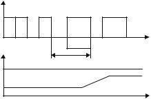
One simple way to do this is to use a PWM timer. By applying a PWM signal to a low-pass filter, the resulting output signal has the amplitude Vout = K × VM where VM is the amplitude of the VPWM signal, and K is the duty cycle (refer to Fig. 7.4).
VPWM
Vmax |
t |
Tp |
T |
VOUT |
Vmax |
Vout |
t |
Fig. 7.4. The analog signal associated with a PWM signal

7.8 Digital-to-Analog Converters |
103 |
RF
-
Vout
+
S3 |
S2 |
S1 |
S0 |
|
2R |
2R |
2R |
2R |
|
Vref |
|
|
|
|
|
R |
R |
R |
2R |
Fig. 7.5. Simplified schematic of a 4-bit DAC, using R-2R ladder network
In cases when a PWM timer is not available, or when the number of PWM channels is less than the required number of analog outputs, the solution is to use special external circuits, called Digital-to-Analog Converter, or DACs. There is a variety of such circuits with different resolutions (the number of bits of the converted word), different conversion time, or different ways to present the result (serial/parallel). The majority of them operate on the same principle, by dividing the current in a ladder type R-2R resistor network. The simplified schematic of a 4-bit DAC based on this principle is presented in Fig. 7.5.
In this circuit, the operational amplifier acts in such a way that the potential of the inverting input is maintained equal to the potential of the non-inverting input, which is connected directly to ground. As a consequence, regardless of the status of the switches S3–S0, the network acts as if all of the 2R resistors, have a terminal connected to ground. This means that the equivalent resistance that loads Vref is constant, equal to R, and the total absorbed current from Vref is also constant, Iref = Vref/R. The currents flowing through the four switches (S3, S2, S1, S0) are I3 = Iref/2, I2 = Iref/4, I1 = Iref/8, I0 = Iref/16. The output voltage is
Vout = −IF × RF
where IF is a fraction of Iref, directed by the switches S3–S0 to the inverting input of the operational amplifier,
IF = b3 × I3 + b2 × I2 + b1 × I1 + b0 × I0
IF = Iref(b0/2 + b1/4 + b2/8 + b3/16)
were (b3–b0) are the bits of the word that must be converted to an analog value.
It follows that the output voltage Vout is proportional to the binary value to be converted.
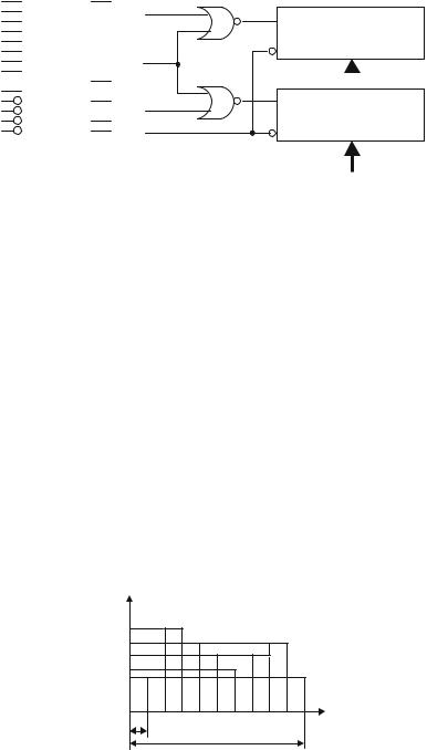
A typical example of a circuit, built on this principle, is MX7224 from Maxim. The functional block diagram and the pin configuration of the circuit are shown in Fig. 7.6.
The circuit is designed so that it can be directly connected to a data bus. When both the CS\ and WR\ signals are active, the data from the bus is transferred to the
104 |
7 |
Interfacing to Analog Signals |
|||||||||||
|
|
|
|
|
|
2 |
|
|
|
|
|
|
|
|
13 |
DB0 |
Vout |
|
|
|
|
|
|
|
|||
|
|
LDAC |
|||||||||||
|
12 |
DB1 |
|
|
|||||||||
|
11 |
DB2 |
|
|
|
|
|
|
|
|
|
||
|
10 |
DB3 |
|
|
|
|
|
|
|
DAC REGISTER |
|||
|
9 |
DB4 |
|
|
|
|
|
|
|
|
|
||
|
8 |
DB5 |
|
|
|
|
|
|
|
|
|
||
|
7 |
DB6 |
|
|
WR |
||||||||
|
6 |
DB7 |
VDD |
18 |
|
|
|
|
|
|
|
||
|
3 |
VREF |
|
|
|
|
|
|
|
|
|||
|
|
1 |
|
|
|
|
|
|
|
||||
|
16 |
|
|
|
VSS |
|
|
|
|
|
|
|
|
|
LDAC |
|
|
|
|
|
|
|
|||||
|
|
CS |
|||||||||||
|
15 |
WR |
|
|
|
||||||||
|
14 |
|
4 |
|
|
|
|
|
INPUT REGISTER |
||||
|
CS |
AGND |
|
|
|
|
|
||||||
|
17 |
5 |
|
RESET |
|||||||||
|
RESET |
DGND |
|
||||||||||
|
|
|
|
|
|
|
|
|
|
|
|
|
|
|
|
MX7224 |
|
|
|
|
|
|
|
|
|
||
DATA BUS
Fig. 7.6. Block diagram and pin configuration of a typical DAC IC
Input Register. The LDAC\ signal controls the transfer of data to the DAC register. When CS\ = 0, WR\ = 0 and LDAC\ = 0, both registers are transparent and the data from the DB0–DB7 inputs is converted to Vout. With this configuration of the control signals the circuit can be directly connected on an output port of the microcontroller
7.8.2 Exercise on Using MX7224
SX 7.6
Using the MX7224 circuit, connected to the PORTA of a 68HC11F1 microcontroller, write a program that generates a signal with the characteristics shown in Fig. 7.7. The reference voltage used is 2.5 V, and the frequency of the internal E clock is 2 MHz. The output signal is periodic with 10-ms period. Figure 7.7 gives the values of the samples for one period.
Solution
The values of the 10 samples, corresponding to a period of the output signal, must be written in the port connected to the DAC at 1-ms intervals. To generate the time
Vout |
|
2.1 |
|
1.2 |
|
0.5 |
|
|
t |
1 |
10ms |
Fig. 7.7. Waveform of the signal referred in the exercise from paragraph 7.8.2
7.8 Digital-to-Analog Converters |
105 |
intervals a timer is required, TOC1 for example, which generates periodic interrupts. The timer interrupt service routine must update the port data. The initiation sequence must configure the PORTA in output mode, enable the TOC1 interrupt, and initialize the pointer XTAB with the address of the ROM table that contains the values of the samples.
INIT_DAC |
LDD |
TOC1 |
|
|
ADDD |
#2000 |
;next interrupt in 1 ms |
|
STD |
TOC1 |
|
|
LDX |
#DACTAB |
|
|
STX |
XTAB |
;init pointer in DACTAB |
|
BSET |
TFLG1,$80 |
;clear OC1F if any |
|
BSET |
TMSK1,$80 |
;enable TOC1 interrupts |
|
LDAA |
#$FF |
|
|
STAA |
DDRA |
;PORTA all lines output |
|
RTS |
|
;end of initialization |
The interrupt service routine must do the following:
•Erase the interrupt flag.
•Prepare the next interrupt from TOC1 to come in 1 ms.
•Write the value from DACTAB in PORTA
•Increment the XTAB pointer, and check if the end of table has been reached. If the end of the table is detected, XTAB must be reinitialized with the starting address.
TOC1_ISR |
BSET |
TFLG1,$80 |
;clear interrupt flag |
|
LDD |
TOC1 |
|
|
ADDD |
#2000 |
;next interrupt in 1 ms |
|
STD |
TOC1 |
|
|
LDX |
XTAB |
|
|
LDAA |
0,X |
;get data from table |
|
STAA |
PORTA |
;write it to DAC |
|
INX |
|
;increment pointer |
|
CPX |
#ENDTAB |
;check for end of table |
|
BHS |
TOC1X |
|
|
STX |
XTAB |
;update pointer and exit |
|
RTI |
|
|
TCO1X |
LDX |
#DACTAB |
;reload pointer if end of |
|
|
|
;table detected |
|
STX |
XTAB |
|
|
RTI |
|
|
The table with the DAC values for the interpolation, considering that the value Vout input $FF.
specified curve is obtained by linear = Vref = 2.5 V corresponds to a binary
106 7 Interfacing to Analog Signals
DACTAB |
DB |
$00 |
|
|
DB |
$33 |
|
|
DB |
$D6 |
|
|
DB |
$A3 |
|
|
DB |
$7A |
|
|
DB |
$4C |
|
|
DB |
$33 |
|
|
DB |
$7A |
|
|
DB |
$A3 |
|
|
DB |
$4C |
|
ENDTAB |
EQU |
* |
;end of table |
Obviously, by modifying the data in DACTAB, it is possible to obtain any waveform for the output signal. The only limitation is imposed by the speed of the processor. For HC11, the 1-ms interval between two successive interrupts is close to the upper limit. The AVR microcontrollers are much faster.

8
Using the Internal EEPROM Memory
8.1 In this Chapter
This chapter contains a description of the EEPROM memory as implemented in the HC11 and AVR families of microcontrollers, as well as a description of the EEPROM control registers, and software examples for erasing and programming the EEPROM.
8.2 Overwiew of the EEPROM Subsystem
In many situations it is required that some program parameters, calibration tables, etc. are stored in nonvolatile memory, able to keep its contents indefinitely after the system is powered off.
The solution to this problem is to include in the structure of the microcontroller an EEPROM memory area (Electrically Erasable Programmable Read Only Memory). Most modern microcontrollers include between 128 bytes and 2 kilobytes of EEPROM.
For technological reasons, erasing and programming the EEPROM requires a 20 V Vpp voltage, obtained by means of a so-called charge pump. The current capability of this internal source is very low, and therefore the charge pump requires a time of around 10 milliseconds to stabilize. The following restrictions apply when accessing the EEPROM:
•Before programming, an EEPROM bit must be erased. The value of an erased bit is 1.
•After an erase or program operation, a 10-ms delay is required for the charge pump to stabilize.
8.3 The EEPROM Memory and the CONFIG Register of HC11
Depending on the model, the microcontrollers of the HC11 family have between 512 and 2048 EEPROM memory bytes, mapped in the general memory map. The starting

108 8 Using the Internal EEPROM Memory
address of the EEPROM memory area differs from one model to another, but, in some cases, the whole EEPROM block can be remapped, by means of the control bits [EE3:EE0] from the CONFIG register.
8.3.1 The Registers Controlling the EEPROM of HC11
HC11 has two registers involved in the control of the EEPROM. These are the PPROG register (EEPROM Programming Control Register) and the BPROT register (EEPROM Block Protect Register). The PPROG register has the following structure:
PPROG |
7 |
6 |
5 |
4 |
3 |
2 |
1 |
0 |
|
ODD |
EVEN |
– |
BYTE |
ROW |
ERASE |
EELAT |
EEPGM |
RESET |
0 |
0 |
0 |
0 |
0 |
0 |
0 |
0 |
The ODD and EVEN bits are used in the special test operating mode and they will not be discussed here.
The BYTE, ROW and ERASE bits control the erase process of the EEPROM, according to Table 8.1.
Table 8.1. The effect of programming the bits BYTE, ROW, and ERASE
BYTE |
ROW |
ERASE |
Erase mode |
|
|
|
|
x |
x |
0 |
Normal read/program |
0 |
0 |
1 |
All locations erased |
0 |
1 |
1 |
A 16 bytes “row” is erased |
1 |
0 |
1 |
One byte is erased |
1 |
1 |
1 |
One byte is erased |
|
|
|
|
•EELAT – EEPROM Latch Control bit
EELAT = 0 EEPROM address and data buses are prepared for normal read op-
erations.
EELAT = 1 EEPROM address and data buses are prepared for write or erase operations. Write operations to EEPROM with EELAT = 1 cause the values of address and data to be retained in special latches.
•EEPGM – EEPROM Program Control bit.
EEPGM = 1 starts the charge pump assuring the programming tension for the EEPROM. The EEPGM bit can be written only if EELAT = 1.
The BPROT register has the following structure:
BPROT |
7 |
6 |
5 |
4 |
3 |
2 |
1 |
0 |
|
– |
– |
– |
PTCON |
BPRT3 |
BPRT2 |
BPRT1 |
BPRT0 |
|
|
|
|
|
|
|
|
|
RESET |
0 |
0 |
0 |
1 |
1 |
1 |
1 |
1 |

8.3 The EEPROM Memory and the CONFIG Register of HC11 |
109 |
Table 8.2. Block addresses associated with BPRTi, valid for 68HC11F1
Bit name Block protected
BPRT0 $xE00–$xE1F
BPRT1 $xE20–$xE5F
BPRT2 $xE60–$xEDF
BPRT3 $xEE0–$xFFF
•PTCON – Protect CONFIG register. When this bit is set to 1, the CONFIG register cannot be written or erased.
•BPRT3–BPRT0 – When these bits are 1, the protection of an EEPROM memory block associated with each bit is activated, as shown in Table 8.2.
The BPROT register can only be written during the first 64 E cycles after RESET. Out of RESET, all BPROT bits are set to 1, which means that the protection is activated. The programming examples presented in the next paragraph assume that all bits of interest in the BPROT register have been erased in the initialization sequence, executed immediately after RESET.
8.3.2 Software Routines to Erase and Write the EEPROM
8.3.2.1 Erasing a Single Byte of EEPROM
The E2BE (EEPROM Byte Erase) subroutine receives in X the address of the byte to be erased. The first step is to write in PPROG a control word, which specifies an erase operation (EELAT = 1 and ERASE = 1) at the byte level (BYTE = 1). The next step is to perform a write operation to the address of the byte to be erased.
When EELAT = 1, the address of the destination of any write operation is stored in special latches, and will be used in further erase or write operations to EEPROM. The actual erase process starts when the EEPGM bit is set, and lasts about 10 milliseconds. After this delay, the PPROG register must be cleared to return to normal operation mode. Here is the subroutine that executes an EEPROM byte erase.
E2BE |
LDAB |
#$16 |
;BYTE=1, ERASE=1, EELAT=1 |
|
STAB |
PPROG |
|
|
STAB |
0,X |
;write operation to latch |
|
|
|
;address |
|
LDAB |
#$17 |
;make EEPGM=1 |
|
STAB |
PPROG |
;start Vpp charge pump |
|
JSR |
DLY10 |
;wait 10 ms |
|
CLR |
PPROG |
;stop Vpp and return to |
|
|
|
read ;mode |
|
RTS |
|
;return to main program |

110 8 Using the Internal EEPROM Memory
8.3.2.2 Writing a Byte to EEPROM
The E2W (EEPROM write) subroutine, listed below, assumes that:
E2W |
LDAB |
#$02 |
;BYTE=0, ERASE=0, EELAT=1 |
|
STAB |
PPROG |
|
|
STAA |
0,X |
;write operation to latch the |
|
|
|
;address and data |
|
LDAB |
#$03 |
;make EEPGM=1 |
|
STAB |
PPROG |
;start Vpp charge pump |
|
JSR |
DLY10 |
;wait 10 ms |
|
CLR |
PPROG |
;stop Vpp and return to read |
|
|
|
;mode |
|
RTS |
|
;return to main program |
•The bit in BPROT associated with the destination address of the write operation is cleared, i.e. the destination is not write protected.
•The destination byte has been previously erased.
•The address of the destination byte is placed in X.
•The data byte to be written in the EEPROM is placed in A.
If ERASE = 1 and BYTE = 0, setting PPROG will initiate an erase sequence on the entire EEPROM memory, called BULK ERASE.
Reading EEPROM while a write or erase operation is in progress (EELAT = 1) will return erroneous data. There is no hardware mechanism to prevent this type of error.
8.3.3 The CONFIG Register
The CONFIG register consists of eight EEPROM cells, organized as a register located in the I/O register block of the MCU. The CONFIG register can be erased or programmed just like any other EEPROM location. The structure of the CONFIG register of 68HC11F1 is as follows:
CONFIG |
7 |
6 |
5 |
4 |
3 |
2 |
1 |
0 |
|
– |
– |
– |
– |
– |
NOCOP |
ROMON |
EEON |
RESET |
0 |
0 |
0 |
0 |
0 |
x |
x |
x |
•NOCOP = 1 disables the COP (Computer Operating Properly) watchdog,
•ROMON = 1 enables the internal ROM.
•EEON = 1 enables the internal EEPROM.
Some members of the HC11 family allow remapping of the EEPROM block to the beginning of any 4 K boundary in the memory map. To this purpose, the most significant four bits of the CONFIG registers, called [EE3:EE2:EE1:EE] are used to