

Microcontrollers in Practice (Mitescu M., 2005)
.pdf3.8 Programming the Asynchronous Serial Interface |
39 |
This time, the processor doesn’t wait indefinitely for a character. It tests from the beginning whether a character is available in SCDR, by checking the RDRF flag. If a character has been received, this is read and saved in a variable, and the carry flag is set to inform the main program about the event. If no character has been received, the carry bit is cleared. Such a reception routine must be called periodically in a program loop, but it has the advantage that the CPU does not hang up until a character is received.
An even better solution would be to use SCI reception interrupts to handle the reception of characters. For this purpose, the initialization routine must be modified to enable the interrupts generated by RDRF.
INIT_SCI |
LDAA |
#$30 |
;see paragraph 3.5 |
|
STAA |
BAUD |
;9600 baud |
|
CLR |
SCCR1 |
;clear M for 8 bit |
|
|
|
;communication |
|
LDAA |
SCSR |
;clear flags if any |
|
LDAA |
SCDR |
|
|
CLR |
QSCI |
|
|
CLR |
QSCIERR |
|
|
LDAA |
#$2C |
;RIE=1, TE=1, RE=1 |
|
STAA |
SCCR2 |
;enable receiver |
|
|
|
;interrupts |
|
..... |
|
|
The control word written into SCCR2 contains the RIE bit set to 1, thus enabling the reception interrupts. Note that, before enabling the interrupts, SCSR and SCDR are read in this sequence in order to clear any flag that might generate a false interrupt. QSCI and QSCIERR are two variables indicating that a character has been received, or that a communication error has been detected. The interrupt service routine looks like this:
SCI_ISR |
LDAA |
SCSR |
|
|
ANDA |
#$0E |
;Isolate all error flags |
|
BNE |
SCIERR |
;if error, inform the |
|
|
|
;main program |
|
LDAA |
SCDR |
;get character |
|
STAA |
SCIRB |
;save it in a buffer |
|
INC |
QSCI |
;true QSCI |
|
RTI |
|
;return from interrupt |
SCIERR |
LDAA |
SCDR |
;read SCDR to clear flags |
|
STAA |
SCIRB |
|
|
INC |
QSCI |
;true QSCI |
|
INC |
QSCIERR |
;true error flag |
|
RTI |
|
|
Note that when a reception error occurs, it is important to read the character received to make sure that the flag that has generated the interrupt is cleared. It is seldom required to analyze what error occurred, because in most cases, the only thing to do is to ask for the character to be retransmitted.

40 3 Using the Asynchronous Serial Interface
Important note. The SCI of HC11 uses two lines of PORTD to implement the transmission and reception lines TxD, RxD. By enabling the SCI transmitter and receiver, the TxD line is automatically configured as an output line, and RxD is configured as an input line, regardless of the contents of DDRD.
3.8.2 Programming the UART of AT90S8535
Here is an example of initializing the UART of AT90S8535 for 19 200 baud, 8 bits per character, no interrupts:
.EQU |
K19200=25 |
;xtal=8 MHz |
|
|
|
|
;BaudRate=19200 |
Init_Uart: |
|
|
|
|
Ldi |
R16,K19200 |
; set baud rate |
|
Out |
UBRR,R16 |
|
|
Ldi |
R16,$18 |
;RXEN=1, TXEN=1 |
|
Out |
UCR,R16 |
|
|
Ret |
|
|
To enable reception interrupts, the control word written to UCR must be modified so that the bit RXCIE = 1 (Reception Complete Interrupt Enable).
.EQU |
K19200=25 |
;xtal=8 MHz |
|
|
|
|
;BaudRate=19200 |
Init_Uart: |
|
|
|
|
Ldi |
R16,K19200 |
; set baud rate |
|
Out |
UBRR,R16 |
|
|
Ldi |
R16,$98 |
;RXEN=1, TXEN=1 |
|
Out |
UCR,R16 |
;RXCIE=1 |
|
Ret |
|
|
Unlike HC11, AVR microcontrollers clear the interrupt flag automatically by hardware, when the interrupt is executed. The CPU status is NOT saved and restored automatically, and therefore the CPU registers used by the interrupt routine must be saved to the stack by software. Here is an example of a simple interrupt service routine for AVR:
Uart_ISR:
Push |
R16 |
;save CPU status |
In |
R16,SREG |
|
Push |
R16 |
|
In |
R16,UDR |
;get character |
Sts |
RECBUF,R16 |
;save it |
Ldi |
R16,$FF |
|
Sts |
QUART,R16 |
;true QUART |
Pop |
R16 |
;restore status |
|
3.8 Programming the Asynchronous Serial Interface |
41 |
Out |
SREG,R16 |
|
Pop |
R16 |
|
Reti |
;return to main |
|
QUART is a software flag that, when true, informs the main program that a character is available. RECBUF is a one-character buffer to store the character received from the UART.
3.8.3 Programming the UART of 8051
The 8051 asynchronous serial interface does not include a dedicated baud rate generator. It uses the internal timer to generate the serial clock. Refer to Chap. 6 to understand how the timer is used in the following initialization routine. The control word written to SCON selects the operating mode 1 for the serial interface, and sets the bit REN = 1 to enable the receiver subsystem.
INIT_UART:
MOV |
SCON,#50H |
;UART mode 1, REN=1 |
MOV |
PCON,#80H |
;SMOD=1 |
MOV |
TMOD,#20H |
;C/T=0, M1=1, M0=0 |
MOV |
TH1,#0FAH |
;auto reload value |
MOV |
TCON,#40H |
;TR1=1 -- start counting |
RET |
|
|
Serial interface interrupts can be enabled by setting the bit ES in the register IE. Below is an example of serial reception and transmission routines, which use RI and TI polling rather than interrupts:
GETCHR: |
|
|
|
|
CLR |
C |
|
|
JB |
RI,GETCHR1 |
;if character received |
|
RET |
|
|
GETCHR1: |
MOV |
A,SBUF |
;get it |
|
CLR |
RI |
;always clear flag! |
|
SETB |
C |
;inform main program |
|
RET |
|
|
SENDCHR: |
|
|
|
|
CLR |
C |
|
|
JB |
TI,SENDCHR1 |
;check if transmitter |
|
|
|
;ready |
|
RET |
|
|
SENDCHR1: |
|
|
|
|
CLR |
TI |
|
|
MOV |
SBUF,A |
;start sending |
|
SETB |
C |
;set carry to inform main |
|
|
|
;program |
|
RET |
|
|

42 3 Using the Asynchronous Serial Interface
3.9 Hardware Interfaces for Serial Communication
The asynchronous serial interface has been created to allow connection between digital devices over relatively long distances. The problem is that, as the distance increases, the effect of parasite capacitance and inductance of the cables becomes more important, and the electromagnetic interference grows stronger. As a consequence, the signals transmitted in this way are distorted and attenuated to such an extent that the information carried by the signals cannot be extracted at the receiver.
To overcome the perturbing effect of long connection cables, several methods of processing the electrical signals have been developed. Before transmission, the signals are transformed by special interfaces, in order to increase their overall immunity to perturbations. This section describes three such interfaces.
3.9.1 The RS232 Interface
RS is an abbreviation for Recommended Standard. The recommendation comes from the Electronics Industry Association (EIA), which proposed in 1969 the RS232 standard, aiming to bring order in the multitude of technical solutions to the problems of serial communication.
The main characteristic of RS232 is that the signals are carried as single voltages, referred to a common ground. The voltage levels associated with the logic levels 0 and 1 are as follows:
For logic 0, the voltage on the communication line must be in the range +6 V to +15 V.
For logic 1, the voltage must be in the range −6 V to −15 V.
In practice, the transmission devices generate ±12 V. The receiving devices accept as logic 0 any signal ranging from +3 V to +15 V, and as logic 1 any signal with the amplitude in the range −3 V to −15 V.
A number of special RS232 interface circuits have been developed. One very popular circuit with this function is MAX232, from Maxim Semiconductors. This contains two RS232 transmitters and two RS232 receivers in the same package. The major advantage of this circuit is that it uses an internal oscillator and four external capacitors to generate the ±12 V power supply sources, starting from a single +5 V
|
VCC C4 22u |
|
|
|
1 |
C1 |
|||||||||
|
2 |
V+ |
C1+ |
|
|
|
|||||||||
|
|
|
|
|
|
|
|
|
|
|
|
|
|
||
|
|
|
|
|
|
|
|
|
C1- |
3 |
22u |
||||
|
|
|
|
|
|
|
|
|
|
||||||
|
|
|
|
|
|
|
|
|
6 |
|
|
|
|
||
|
|
|
|
|
|
|
|
|
V- |
4 |
C2 |
||||
|
|
|
|
|
|
|
|
|
C2+ |
||||||
|
|
|
|
|
|
|
|
|
|
|
|
|
|
||
|
|
|
|
|
C3 22u |
|
|
|
|
|
|||||
|
|
|
|
|
|
|
|
|
|
|
|||||
|
|
|
|
|
|
|
|
5 |
22u |
||||||
GND |
|
|
C2- |
||||||||||||
14 |
|
11 |
TxD |
||||||||||||
|
|
|
|
|
Tx 232 |
T1OUT |
T1IN |
||||||||
|
|
|
|
7 |
10 |
|
|
|
|||||||
|
|
|
|
Rx 232 |
|
T2OUT |
T2IN |
RxD |
|||||||
|
|
|
|
|
13 |
12 |
|||||||||
|
|
|
|
|
|
|
|
|
|
R1IN |
R1OUT |
|
|
|
|
|
|
|
|
|
|
|
|
|
8 |
9 |
|
|
|
||
|
|
|
|
|
|
|
|
|
R2IN |
R2OUT |
|
|
|
||
|
|
|
|
|
|
|
|
|
|
|
|
|
|
||
|
|
|
|
|
|
|
|
|
|
|
|
|
|
|
|
|
|
|
|
|
|
|
|
|
|
MAX232 |
|
|
|
|
|
Fig. 3.6. A typical RS232 interface circuit MAX232

3.9 Hardware Interfaces for Serial Communication |
43 |
RxD
+5V
 Rx232 +12V
-12V
Fig. 3.7. Waveforms illustrating the level conversion performed by MAX232
power supply. Most of the projects described in this book use this circuit. The schematic of an RS232 interface using MAX232 is shown in Fig. 3.6.
Figure 3.7 shows the waveforms of a signal before and after the MAX232 driver.
3.9.2 Differential Communication. The Interfaces RS422 and RS485
The RS232 interface guarantees safe transmission up to a distance of 15 meters, at a maximum communication speed of 19 200 baud. In practice, these limits are often exceeded, but the overall reliability of the communication system drops. For longer distances, and higher communication speed, a different interface is required.
The interfaces RS422 and RS485 use two conductors to transmit each digital signal, the logic levels being defined by the relative difference of potential between the two conductors. The transmitter’s line driver controls the voltage levels on the two conductors, so that the difference of potential between them is positive for logic 1 and negative for logic 0, as illustrated in Fig. 3.8. This type of transmission is called differential.
The advantage of the differential interface is that the electromagnetic interference and the ground potential differences appear as common mode voltage for the receiver, and they are rejected. This creates a much better immunity to perturbations and allows communication speeds up to 10 Mb per second and cable length up to 1200 meters, using twisted pair cable. The receiver requires at least 200 mV differential input signal in order to reconstruct the original signal.
X
A
XA
 B
B
B
Fig. 3.8. Waveforms for differential transmission
44 3 Using the Asynchronous Serial Interface
DE |
|
|
|
|
|
A |
|
|
|
D |
Input |
Enable |
Output |
|
|
D |
DE |
A |
B |
|
B |
|
|
|
|
H |
H |
H |
L |
|
L |
H |
L |
H |
R |
X |
L |
Z |
Z |
|
|
|
|
|
RE |
|
|
|
|
Fig. 3.9. Typical RS422/RS485 transceiver circuit
Both the RS422 and RS485 interfaces use differential communication. The difference is that RS422 is designed for point-to-point communication. Only one transmitter and up to 10 receivers may be connected on a conductor pair, in a simplex transmission. RS485 allows multipoint communication, i. e. up to 32 transmitters/receivers may be connected on a conductor pair, in a half-duplex communication. Therefore, the RS485 transmitters must be able to drive their outputs into a high-impedance status, allowing other transmitters to control the communication line. Note that the RS485 standard defines only the electrical characteristics of the signals and devices, and not the rules for accessing the RS485 bus, i. e. the communication protocol.
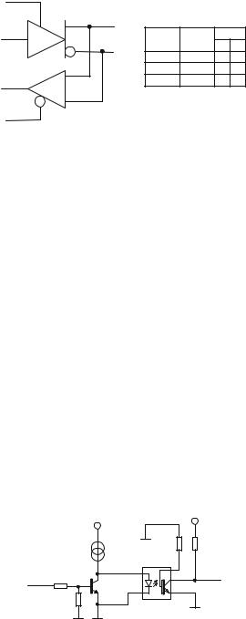
A typical RS422/RS485 circuit is SN 75176. The functional block diagram of this circuit is shown in Fig. 3.9.
This circuit contains in the same capsule one differential transmitter, and one differential receiver, having individual enable inputs: DE (Driver Enable) active HIGH, and RE\backslash(Receiver Enable) active LOW. When DE = 0, the outputs A, B are in a high impedance status, thus the transmitter is virtually disconnected from the communication line, leaving the control of the line to other similar devices.
3.9.3 The Current Loop Interface
When the length of the communication line is higher than 1 km, or in harsh industrial environments, where galvanic isolation between the transmitter and the receiver is essential, it is possible to use the interface presented in Fig. 3.10.
VPP |
|
|
VCC2 |
|
|
|
|
||
|
GND2 |
R2 |
R1 |
|
|
I0 |
|
|
|
|
OK1 |
6 |
|
|
T1 |
1 |
|
||
5 |
RxD |
|||
TxD R3 |
|
|||
|
|
|
||
|
2 |
4 |
|
|
R5 |
CNY17 |
|
||
|
GND2 |
|||
|
|
|
||
GND |
GND |
|
|
|
Fig. 3.10. Current loop transmission circuit
3.10 Basic Principles of Networking with Microcontrollers |
45 |
The current generated by I0 closes to the ground either through the transistor T1, when this is saturated, or through the LED of the optocoupler OK1, when T1 is blocked. As a consequence, the waveform of the signal in the collector of the optocoupler’s transistor reproduces the TxD signal. Such a circuit can be used for point-to-point communication systems to transmit data at 9600 bps, over cables a few kilometers long.
3.10 Basic Principles of Networking with Microcontrollers, Using the Asynchronous Serial Interface
A microcontroller-based device can be connected to a network if, at the hardware level, it possesses a communication interface which allows multipoint communication, and, at the software level, is programmed to observe a set of rules concerning the access to the communication channel. This set of rules defines the network communication protocol.
From the hardware point of view, the most common solution used to implement microcontroller-based networks uses the RS485 differential communication interface.
At the software level, a multitude of protocols has been developed, most of them being structured as MASTER–SLAVE protocols. In a MASTER–SLAVE structured network, a single device, called the MASTER, initiates all data transfers on the communication bus. Each SLAVE device has a unique identification code, or address. The MASTER device starts the communication by sending data packets that are received and decoded by all SLAVE devices. Only one SLAVE is authorized to answer the query – the one that recognizes its own address in the data packet received.
The general structure of data packets transferred in a network is given below:
Header |
Body |
CRC |
Tail |
|
|
|
|
The fields Header and Tail are predefined sequences that define the beginning and the end of the packet. The body of the packet must contain the address of the destination slave device, the operation code, and, of course, a data field. The CRC field is a checksum used to detect communication errors, as described in Sect. 3.3. Assuming that all the bytes in the packet are ASCII codes, then the Header and Tail fields can be reduced to a single byte, e. g. STX (Start of Text – $02) for the header, and EOT (End of Text+– $04) for the tail.
Example Design a simple communication protocol for a microcontroller network comprising one MASTER device and up to 10 slave devices. Each slave device must be able to report the status of two digital inputs, and to change the status of two digital outputs, by executing specific commands from the master device.
Solution To match these requirements, the structure of the body of the packets sent by MASTER may be the following:
Opcode |
SADR |
Data1 |
Data2 |
|
|
|
|
46 3 Using the Asynchronous Serial Interface
The opcode must identify the two possible operations: reporting the status of the inputs, and changing the status of the output lines, e. g. the opcode may be the ASCII character ‘I’ for read input, and ASCII ‘O’ for write output.
SADR is the address of the slave required to perform the operation indicated by the opcode. Since the maximum number of slaves in the network is 10, SADR may be the ASCII representation of the numbers ‘0’–‘9’.
Data1 and Data2 are two bytes reserved for the logic values of the inputs and outputs. In case of a ‘write output’ command, these bytes define the new status of the outputs: ‘0’, ‘1’, or ‘T’ (Toggle). In case of a ‘read input’ command, these bytes have no meaning, and always have the value ‘0’. They are maintained in the packet for the sole purpose of keeping the length of the packets constant.
All packets sent by MASTER must have an answer from the addressed slave. The packets sent by the slaves have the same structure, but the opcodes are different, e. g. ACK (acknowledge $06) for a command received and executed correctly, and NAK (negative acknowledge $15) for a packet received with the wrong CRC. When the slave answers with a NAK type packet, the MASTER repeats the query.
See Chap. 13 for the detailed description of an implementation of this protocol, used to interrogate a number of addressable sensors.
3.11 Exercises
SX 3.1
What is the error contained in the interrupt service routine for the reception of characters on SCI for HC11 listed below?
SCI_ISR |
LDAA |
SCSR |
|
|
ANDA |
#$0E |
;Isolate error flags |
|
BNE |
SCIERR |
;if error, inform the main |
|
|
|
;program |
|
LDAA |
SCDR |
;get character |
|
STAA |
SCIRB |
;save it in a buffer |
|
INC |
QSCI |
;true QSCI |
|
RTI |
|
;return from interrupt |
SCIERR |
INC |
QSCIERR |
;true error flag |
|
RTI |
|
|
Solution
The SCI reception interrupt of HC11 is generated when (RIE = 1) AND ((RDRF = 1) OR (OR = 1)), i. e. when the interrupt is enabled, and one of the conditions RDRF = 1 (character received) or OR = 1 (overrun error – a new character is received, and the previous character has not yet been read by the software).
Both RDRF and OR flags are cleared by successively reading SCSR and SCDR. In the interrupt service routine listed above, everything works fine until an error occurs. In this case, the error is detected, and the program jumps to the label SCIERR,
3.11 Exercises |
47 |
where it reaches RTI without reading SCDR. As a consequence, the flag that generated the interrupt is NOT cleared, and a new interrupt is generated right after RTI.
Remember that any interrupt service routine must clear the condition that generated the interrupt.
SX 3.2
What is the main difference between the RS422 and RS485 interfaces?
Solution
Both RS422 and RS485 are designed for differential communication. The main difference between the two standards is that RS422 is aimed at point-to-point communication, where only one transmitter is connected to the communication line.
RS485 is intended for multipoint communication where more than one transmitter is allowed to access the serial bus. Therefore, the RS485 line drivers must be able to go to a high impedance status.
Normally the RS485 interface circuits can be used to implement RS422 point-to- point communication by simply keeping the transmission driver permanently active.
SX 3.3
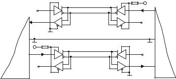
Draw the schematic of an RS422 full duplex communication line, using the SN75176 circuit, described in Sect. 3.9.2.
Solution
In full duplex communication it is possible to receive a character during the transmission of another. For this to be possible, the transmission and reception lines must be physically distinct. In case of differential communication, two conductors are required for transmission and two others for reception.
R2 |
VCC2 |
|
TxD |
RxD |
|
GND |
|
R1 |
GND |
VCC1 |
|
TxD |
|
|
RxD |
GND |
Microcontroller 2 |
Microcontroller 1 |
Fig. 3.11. Implementation of a full duplex RS422 communication line using SN75176
48 3 Using the Asynchronous Serial Interface
The SN75176 circuit can operate as a RS422 transmitter or receiver, if the DE or RE signals are permanently active. This means that two SN75176 circuits are required at each end of the communication line, as shown in Fig. 3.11.
Both the RS232 and RS422 interfaces are used for point-to-point communication links. The difference is that RS422 works over much longer distances than RS232.