

Chapter 2 - Microcontroller PIC16F84
2.8 EEPROM Data memory
PIC16F84 has 64 bytes of EEPROM memory locations on addresses from 00h to 63h that can be written to or read from. The most important characteristic of this memory is that it does not loose its contents during supply. That practically means that what is written to it remains even if microcontroller is turned off. Data can be retained in EEPROM without supply for up to 40 years (as maker of PIC16F84 microcontroller says), and up to 10000 cycles of writing can be executed.
In practice, EEPROM memory is used for storing important data or some process parameters. One such parameter is a given temperature, assigned when setting up a temperature regulator to some process. In case that this data isn't retained, it will be necessary to adjust a given
temperature after each loss of supply. Since this is very impractical (and even dangerous), makers of microcontrollers have began installing one smaller type of EEPROM memory.
EEPROM memory is contained in a special memory space and can be accessed through special registers. These registers are:
•EEDATA at address 08h, which holds data that is read or that needs to be written.
•EEADR at address 09h, which contains an address of EEPROM location being accessed.
•EECON1 at address 88h, which contains control bits.
•EECON2 at address 89h. This register does not exist physically and serves to protect EEPROM from accidental writing.
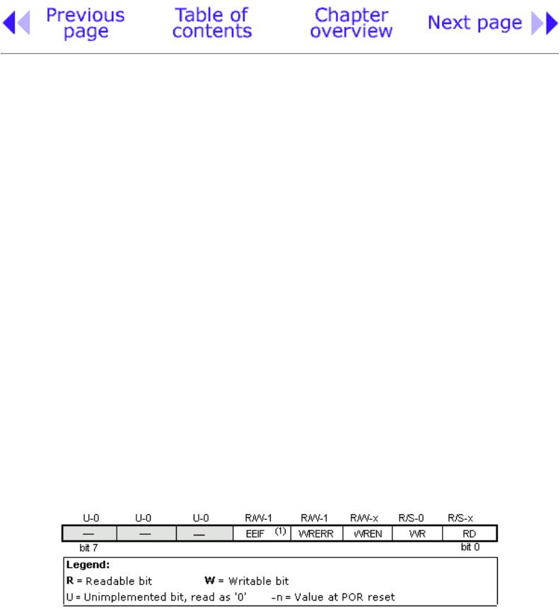
EECON1 register at address 88h is a control register with five applied bits.
Bits 5, 6 and 7 are not used, and when read always are zero. Interpretation of EECON1 register bits follows.
EECON1 Register
bit 0 RD (Read Control bit)
Setting this bit initializes transfer of data from address defined in EEADR to EEDATA register. Since time is not as essential in reading data as in writing, data from EEDATA can already be used further in the next instruction.
http://www.mikroelektronika.co.yu/english/books/2_09Poglavlje.htm (1 of 3) [30/12/2001 16:53:47]
Chapter 2 - Microcontroller PIC16F84
1=initializes reading 0=does not initialize reading
bit 1 WR (Write Control bit)
Setting of this bit initializes writing data from EEDATA register to the address on EEADR register. 1=initializes writing
0=does not initialize writing
bit 2 WREN (EEPROM Write Enable bit) Enables writing to EEPROM If this bit is not set, microcontroller will not allow writing to EEPROM. 1=writing allowed
0=writing disallowed
bit 3 WRERR (EEPROM Error Flag bit) Error during writing to EEPROM
This bit is set only in cases when writing to EEPROM was interrupted by a reset signal or by running out of time in watchdog timer (if it's activated).
1=error occured 0=error did not occur
bit 4 EEIF (EEPROM Write Operation Interrupt Flag bit) Bit used to inform that writing data to EEPROM has ended.
When writing has terminated, this bit will be set automatically. Programmer must reset EEIF bit in his program in order to detect new termination of writing.
1=writing terminated
0=writing not terminated yet, or has not started
Reading from EEPROM Memory
Setting the RD bit initializes transfer of data from address found in EEADR register to EEDATA register. As in reading data we don't need so much time as in writing, data taken over from EEDATA register can already be used further in the next instruction.
Sample of the part of a program which reads data in EEPROM, could look something like the following:
After the last program instruction, contents from an EEPROM address zero can be found in working register w.
Writing to EEPROM Memory
In order to write data to EEPROM location, programmer must first write address to EEADR register and data to EEDATA register. Only then is it useful to set WR bit which sets the whole action in
http://www.mikroelektronika.co.yu/english/books/2_09Poglavlje.htm (2 of 3) [30/12/2001 16:53:47]
Chapter 2 - Microcontroller PIC16F84
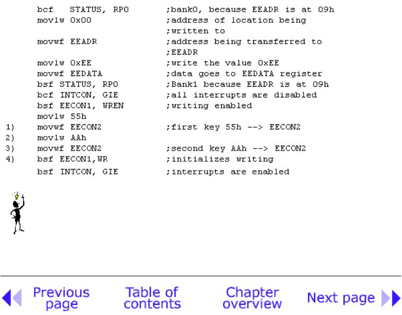
motion. WR bit will be reset, and EEIF bit set following a writing which may be used in processing interrupts. Values 55h and AAh are the first and the second key which make it impossible for accidental writing to EEPROM to occur. These two values are written to EECON2 which serves only that purpose, to receive these two values and thus prevent any accidental writing to EEPROM memory. Program lines marked as 1, 2, 3, and 4 must be executed in that order in even time intervals. Therefore, it is very important to turn off interrupts which could change the timing needed for executing instructions. After writing, interrupts can be enabled again in the end.
Example of the part of a program which writes data 0xEE to first location in EEPROM memory could look something like the following:
It is recommended that WREN be turned off the whole time except when writing data to EEPROM, so that possibility of accidental writing would be minimal.
All writing to EEPROM will automatically clear a location prior to writing anew!
© Copyright 1999. mikroElektronika. All Rights Reserved. For any comments contact webmaster.
http://www.mikroelektronika.co.yu/english/books/2_09Poglavlje.htm (3 of 3) [30/12/2001 16:53:47]

Chapter 3 - Instruction Set
CHAPTER 3
Instruction Set
Introduction
Instruction set in PIC16Cxx microcontroller family
Data Transfer
Arithmetic and logic
Bit operations
Directing the program flow
Instruction execution period
Word list
Introduction
We have already mentioned that microcontroller is not like any other integrated circuit. When they come out of production most integrated circuits are ready to be built into devices which is not the case with microcontrollers. In order to "make" microcontroller perform a task, we have to tell it exactly what to do, or in other words we must write the program microcontroller will execute. We will describe in this chapter instructions which make up the assembler, or program language for PIC microcontrollers of lower standard.
Instruction Set in PIC16Cxx Microcontroller Family
Complete set which encompasses 35 instructions is given in the following table. A reason for such a small number of instructions lies primarily in the fact that we are talking about a RISC microcontroller whose instructions are well optimized considering the speed of work, architectural simplicity and code compactness. The only drawback is that programmer is expected to master "uncomfortable" technique of using a modest set of 35 instructions.
http://www.mikroelektronika.co.yu/english/books/3_Poglavlje.htm (1 of 5) [30/12/2001 16:53:49]
Chapter 3 - Instruction Set
Data transfer
Transfer of data in a microcontroller is done between work (W) register and an 'f' register that represents any location in internal RAM (regardless whether those are special or general purpose registers).
First three instructions (look at the following table) provide for a constant being written in W register (MOVLW is short for MOVe Literal to W), and for data to be copied from W register onto RAM and data from RAM to be copied onto W register (or on the same RAM location, at which point only the status of Z flag changes). Instruction CLRF writes constant 0 in 'f ' register, and CLRW writes constant 0 in register W. SWAPF instruction exchanges places of the 4-bit nibbles crosswise inside a register.
Arithmetic and logic
Of all arithmetic operations, PIC like most microcontrollers supports only subtraction and addition. Flags C, DC and Z are set depending on a result of addition or subtraction, but with one exception: since subtraction is performed like addition of a negative value, C flag is inverse following a subtraction. In other words, it is set if operation is possible, and reset if larger number was subtracted from a smaller one.
Logic one of PIC has capability of performing operations AND, OR, EX-OR, negations (COMF) and rotation (RLF and RRF).
Instructions which rotate the register contents move bits inside a register through flag C by one space to the left (toward bit 7), or to the right (toward bit 0). Bit which "comes out" of a register is written in flag C, and status of that flag is written in a bit on the "opposite side" of the register.
Bit operations
Instructions BCF and BSF do setting or resetting of one bit anywhere in the memory. Even though this seems like a simple operation, it is executed so that CPU first reads the whole byte, changes one bit in it and then writes in the entire byte at the same place.
Directing a program flow
Instructions GOTO, CALL and RETURN are executed the same way as on all other microcontrollers, only stack is independent of internal RAM and limited to eight levels.
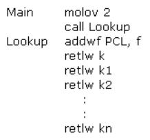
'RETLW k' instruction is identical with RETURN instruction, except that before coming back from a subprogram a constant defined by instruction operand is written in W register. This instruction enables us to design easily the Lookup tables (lists). Mostly we use them by determining data position on our table adding it to the address at which the table begins, and then we read data from that location (which is usually found in program memory).
Table can be formed as a subprogram which consists of a series of 'RETLW k' instructions, where 'k' constants are members of the table.
http://www.mikroelektronika.co.yu/english/books/3_Poglavlje.htm (2 of 5) [30/12/2001 16:53:49]
Chapter 3 - Instruction Set
We write the position of a member of our table in W register, and using CALL instruction we call a subprogram which makes up the table. First subprogram line ADDWF PCL, f adds the position of a W register member to the starting address of our table, found in PCL register, and so we get the real data address in program memory. When returning from a subprogram we will have in W register the contents of an addressed table member. In a previous example, constant 'k2' will be in W register following a return from a subprogram.
RETFIE (RETurn From Interrupt - Interrupt Enable) is a return from interrupt routine and differs from a RETURN only in that it automatically sets GIE (Global Interrupt Enable) bit. Upon an interrupt, this bit is automatically reset. As interrupt begins, only the value of program counter is put at the top of a stack. No automatic storing of register status is provided.
Conditional jumps are synthesized into two instructions: BTFSC and BTFSS. Depending on a bit status in 'f' register that is being tested, instructions skip or don't skip over the next program instruction.
Instruction Execution Period
All instructions are executed in one cycle except for conditional branch instructions if condition is true, or if the contents of program counter is changed by some instruction. In that case, execution requires two instruction cycles, and the second cycle is executed as NOP (No Operation). Four oscillator clocks make up one instruction cycle. If we are using an oscillator with 4MHz frequency, the normal time for executing an instruction is 1 µs, and in case of conditional branching, execution period is 2 µs.
Word list
f any memory location in a microcontroller W work register
b bit position in 'f' register d destination bit
label group of eight characters which marks the beginning of a part of the program TOS top of stack
[] option
<> register bit field
http://www.mikroelektronika.co.yu/english/books/3_Poglavlje.htm (3 of 5) [30/12/2001 16:53:49]

Chapter 3 - Instruction Set
*1 If I/O port is source operand, status on microcontroller pins is read
*2 If this instruction is executed on TMR register and if d=1, prescaler assigned to that timer will automatically be cleared
*3 If PC is modified, or test result =1, instruction is executed in two cycles.
http://www.mikroelektronika.co.yu/english/books/3_Poglavlje.htm (4 of 5) [30/12/2001 16:53:49]

Chapter 3 - Instruction Set
© Copyright 1999. mikroElektronika. All Rights Reserved. For any comments contact webmaster.
http://www.mikroelektronika.co.yu/english/books/3_Poglavlje.htm (5 of 5) [30/12/2001 16:53:49]

Chaptec 9 78Bssembly Language Programming
CHAPTER 4
Bssembly Language Programming
Introduction
Bn example of a written program
Control directives
●4.1 define
●4.2 include
●4.3 constant
●4.4 variable
●4.5 set
●4.6 equ
●4.7 org
●4.8 end
Conditional instructions
●4.9 if
●4.10 else
●4.11 endif
●4.12 while
●4.13 endw
●4.14 ifdef
●4.15 ifndef
Data directives
● 4.16 cblock
http://www.mikroelektronika.co.yu/english/books/4_Poglavlje.htm (1 of 19) [30/12/2001 16:53:53]

Chapter 4 - Assembly Language Programming
●4.17 endc
●4.18 db
●4.19 de
●4.20 dt
Configurating a directive
●4.21 _CONFIG
●4.22 Processor
Assembler arithmetic operators
Files created as a result of program translation
Macros
Introduction
The ability to communicate is of great importance in any field. However, it is only possible if both communication partners know the same language, or follow the same rules during communication. Using these principles as a starting point, we can also define communication that occurs between microcontrollers and man . Language that microcontroller and man use to communicate is called "assembly language". The title itself has no deeper meaning, and is analogue to names of other languages , ex. English or French. More precisely, "assembly language" is just a passing solution. Programs written in assembly language must be translated into a "language of zeros and ones" in order for a microcontroller to understand it. "Assembly language" and "assembler" are two different notions. The first represents a set of rules used in writing a program for a microcontroller, and the other is a program on the personal computer which translates assembly language into a language of zeros and ones. A program that is translated into "zeros" and "ones" is also called "machine language".
http://www.mikroelektronika.co.yu/english/books/4_Poglavlje.htm (2 of 19) [30/12/2001 16:53:53]
Chapter 4 - Assembly Language Programming
The process of communication between a man and a microcontoller
Physically, "Program" represents a file on the computer disc (or in the memory if it is read in a microcontroller), and is written according to the rules of assembly or some other language for microcontroller programming. Man can understand assembly language as it consists of alphabet signs and words. When writing a program, certain rules must be followed in order to reach a desired effect. A Translator interprets each instruction written in assembly language as a series of zeros and ones which have a meaning for the internal logic of the microcontroller.
Lets take for instance the instruction "RETURN" that a microcontroller uses to return from a subprogram.
When the assembler translates it, we get a 14-bit series of zeros and ones which the microcontroller knows how to interpret.
Example: RETURN 00 0000 0000 1000
Similar to the above instance, each assembly instruction is interpreted as corresponding to a series of zeros and ones.
The place where this translation of assembly language is found, is called an "execution" file. We will often meet the name "HEX" file. This name comes from a hexadecimal representation of that file, as well as from the appendage "hex" in the title, ex. "run through.hex". Once it is generated, the execution file is read in a microcontroller through a programmer.
An Assembly Language program is written in a program for text processing (editor) and is capable of producing an ASCII file on the computer disc or in specialized surroundings such as MPLAB - to be explained in the next chapter.
Assembly language
Basic elements of assembly language are:
●Labels
●Instructions
●Operands
●Directives
●Comments
Labels
A Label is a textual designation (generally an easy-to-read word) for a line in a program, or section of a program where the micro can jump to - or even the beginning of set of lines of a program. It can also be used to execute program branching (such as Goto .......) and the program can even have a condition that must be met for the Goto instruction to be executed. It is important for a label to start with a letter of the alphabet or with an underline "_". The length of the label can be up to 32 characters. It is also important that a label starts in the first row.
http://www.mikroelektronika.co.yu/english/books/4_Poglavlje.htm (3 of 19) [30/12/2001 16:53:53]
Chapter 4 - Assembly Language Programming
Instructions
Instructions are already defined by the use of a specific microcontroller, so it only remains for us to follow the instructions for their use in assembly language. The way we write an instruction is also called instruction "syntax". In the following example, we can recognize a mistake in writing because instructions movlp and gotto do not exist for the PIC16F84 microcontroller.
Operands
Operands are the instruction elements for the instruction is being executed. They are usually registers or variables or constants. Constants are called "literals." The word literal means "number."
http://www.mikroelektronika.co.yu/english/books/4_Poglavlje.htm (4 of 19) [30/12/2001 16:53:53]

Chapter 4 - Assembly Language Programming
Comments
Comment is a series of words that a programmer writes to make the program more clear and legible. It is placed after an instruction, and must start with a semicolon ";".
Directives
A directive is similar to an instruction, but unlike an instruction it is independent on the microcontroller model, and represents a characteristic of the assembly language itself. Directives are usually given purposeful meanings via variables or registers. For example, LEVEL can be a designation for a variable in RAM memory at address 0Dh. In this way, the variable at that address can be accessed via LEVEL designation. This is far easier for a programmer to understand than for him to try to remember address 0Dh contains information about LEVEL.
An example of a written program
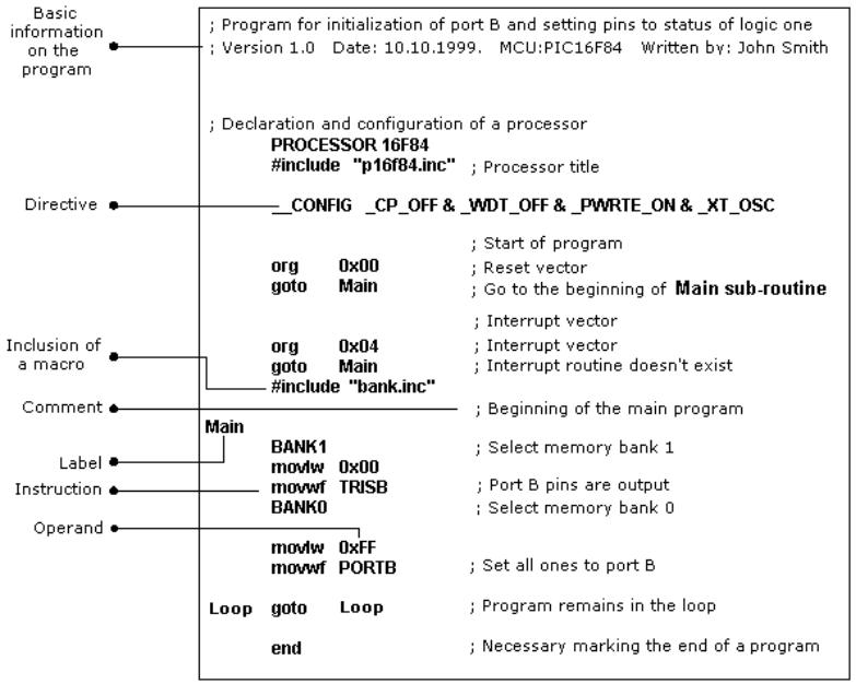
The following example illustrates a simple program written in assembly language respecting the basic rules.
When writing a program, beside mandatory rules, there are also some rules that are not written down but need to be followed. One of them is to write the name of the program at the beginning, what the program does, its version, date when it was written, type of microcontroller it was written for, and the programmer's name.
http://www.mikroelektronika.co.yu/english/books/4_Poglavlje.htm (5 of 19) [30/12/2001 16:53:53]
Chapter 4 - Assembly Language Programming
Since this data isn't important for the assembly translator, it is written as comments. It should be noted that a comment always begins with a semicolon and it can be placed in a new row or it can follow an instruction. It's best kept in the third row to make the layout easy to follow.
After the opening comment has been written, the directive must be included. This is shown in the example above.
In order to function properly, we must define several microcontroller parameters such as: - type of oscillator,
-whether watchdog timer is turned on, and
-whether internal reset circuit is enabled. All this is defined by the following directive:
_CONFIG _CP_OFF&_WDT_OFF&PWRTE_ON&XT_OSC
When all the needed elements have been defined, we can start writing a program.
First, it is necessary to determine an address from which the microcontroller starts, following a power supply start-up. This is (org 0x00).
http://www.mikroelektronika.co.yu/english/books/4_Poglavlje.htm (6 of 19) [30/12/2001 16:53:53]
Chapter 4 - Assembly Language Programming
The address from which the program starts if an interrupt occurs is (org 0x04).
Since this is a simple program, it will be enough to direct the microcontroller to the beginning of a program with a "goto Main" instruction.
The instructions found in the Main sub-routine select memory bank1 (BANK1) in order to access TRISB register, so that port B can be declared as an output (movlw 0x00, movwf TRISB).
The next step is to select memory bank 0 and place status of logic one on port B (movlw 0xFF, movwf PORTB), and thus the main program is finished.
We need to make another loop where the micro will be held so it doesn't "wander" if an error occurs. For that purpose, one infinite loop is made where the micro is retained while power is connected. The necessary "end" at the conclusion of each program informs the assembly translator that no more instructions are in the program.
Control directives
4.1 #DEFINE Exchanges one piece of text for another
Syntax:
#define<name> [<text which changes name>]
Description:
Each time <name> appears in the program , it will be exchanged for <text which changes name>.
Example:
#define turned on 1 #define turned off 0
Similar directives: #UNDEFINE, IFDEF,IFNDEF
4.2 INCLUDE Include an additional file in a program
Syntax:
#include <file_name> #include "
Description:
An application of this directive has the effect as though the entire file was copied to a place where the "include" directive was found. If the file name is in the square brackets, we are dealing with a system file, and if it is inside quotation marks, we are dealing with a user file. The directive "include" contributes to a better layout of the main program.
Example:
#include <regs.h> #include "subprog.asm"
4.3 CONSTANT Gives a constant numeric value to the textual
http://www.mikroelektronika.co.yu/english/books/4_Poglavlje.htm (7 of 19) [30/12/2001 16:53:53]
Chapter 4 - Assembly Language Programming
designation
Syntax:
Constant <name>=<value>
Description:
Each time that <name> appears in program, it will be replaced with <value>.
Example:
Constant MAXIMUM=100
Constant Length=30
Similar directives: SET, VARIABLE
4.4 VARIABLE Gives a variable numeric value to textual designation
Syntax:
Variable<name>=<value>
Description:
By using this directive, textual designation changes with particular value.
It differs from CONSTANT directive in that after applying the directive, the value of textual designation can be changed.
Example: variable level=20
variable time=13
Similar directives: SET, CONSTANT
4.5 SET Defining assembler variable
Syntax:
<name_variable>set<value>
Description:
To the variable <name_variable> is added expression <value>. SET directive is similar to EQU, but with SET directive name of the variable can be redefined following a definition.
Example: level set 0
length set 12 level set 45
Similar directives: EQU, VARIABLE
4.6 EQU Defining assembler constant
Syntax:
http://www.mikroelektronika.co.yu/english/books/4_Poglavlje.htm (8 of 19) [30/12/2001 16:53:53]
Chapter 4 - Assembly Language Programming
<name_constant> equ <value>
Description:
To the name of a constant <name_constant> is added value <value>
Example: five equ 5
six equ 6 seven equ 7
Similar instructions: SET
4.7 ORG Defines an address from which the program is stored in microcontroller memory
Syntax:
<label>org<value>
Description:
This is the most frequently used directive. With the help of this directive we define where some part of a program will be in the program memory.
Example:
Start org 0×00 movlw movwf
The first two instructions following the first 'org' directive are stored from address 00, and the other two from address 10.
4.8 END End of program
Syntax: end
Description:
At the end of each program it is necessary to place 'end' directive so that assembly translator would know that there are no more instructions in the program.
Example:
.
.
movlw 0xFF movwf PORTB end
Conditional instructions
http://www.mikroelektronika.co.yu/english/books/4_Poglavlje.htm (9 of 19) [30/12/2001 16:53:53]
Chapter 4 - Assembly Language Programming
4.9 IF Conditional program branching
Syntax: if<conditional_term>
Description:
If condition in <conditional_term> is met, part of the program which follows IF directive will be executed. And if it isn't, then the part following ELSE or ENDIF directive will be executed.
Example: if nivo=100
goto PUNI else
goto PRAZNI endif
Similar directives: #ELSE, ENDIF
4.10 ELSE 'IF' alternative to program block with conditional terms
Syntax:
Else
Description:
Used with IF directive as an alternative if conditional term is incorrect.
Example:
If time< 50 goto SPEED UP
else goto SLOW DOWN endif
Similar instructions: ENDIF, IF
4.11 ENDIF End of conditional program section
Syntax: endif
Description:
Directive is written at the end of a conditional block in order for the assembly translator to know that it is the end of the conditional block
Example:
If level=100 goto LOADS else
goto UNLOADS endif
http://www.mikroelektronika.co.yu/english/books/4_Poglavlje.htm (10 of 19) [30/12/2001 16:53:53]
Chapter 4 - Assembly Language Programming
Similar directives: ELSE, IF
4.12 WHILE Execution of program section as long as condition is met
Syntax:
while<condition>
.
endw
Description:
Program lines between WHILE and ENDW will be executed as long as condition is met. If a condition stops being valid, program continues executing instructions following ENDW line. Number of instructions between WHILE and ENDW can be 100 at the most, and number of executions 256.
Example:
While i<10 i=i+1 endw
4.13 ENDW End of conditional part of the program
Syntax: endw
Description:
Instruction is written at the end of the conditional WHILE block, so that assembly translator would know that it is the end of the conditional block
Example: while i<10
i=i+1
endw
Similar directives: WHILE
4.14 IFDEF Execution of a part of the program if symbol is defined
Syntax:
ifdef<designation>
Description:
If designation <designation> is previously defined (most commonly by #DEFINE instruction), instructions which follow are executed until ELSE or ENDIF directives are not reached.
Example:
#define test
.
http://www.mikroelektronika.co.yu/english/books/4_Poglavlje.htm (11 of 19) [30/12/2001 16:53:53]
Chapter 4 - Assembly Language Programming
ifdef test ;how the test is defined
......; instructions from these lines will execute endif
Similar directives: #DEFINE, ELSE, ENDIF, IFNDEF, #UNDEFINE
4.15 IFNDEF Execution of a part of the program if symbol is defined
Syntax:
ifndef<designation>
Description:
If designation <designation> was not previously defined, or if its definition was erased with directive #UNDEFINE, instructions which follow are executed until ELSE or ENDIF directives are not reached.
Example:
#define test
..........
#undefine test
..........
ifndef test ;how the test is undefined
..... .; instructions from these lines will execute endif
Similar directives: #DEFINE, ELSE, ENDIF, IFDEF, #UNDEFINE
Data Directives
4.16 CBLOCK Defining a block for the named constants
Syntax:
Cblock [<term>]
<label>[:<increment>], <label>[:<increment>]......
endc
Description:
Directive is used to give values to named constants. Each following term receives a value greater by one than its precursor. If <increment> parameter is also given, then value given in <increment> parameter is added to the following constant.
Value of <term> parameter is the starting value. If it is not given, it is considered to be zero.
Example:
Cblock 0x02
First, second, third ;first=0x02, second=0x03, third=0x04 endc
cblock 0x02
first : 4, second : 2, third ;first=0x06, second=0x08, third=0x09
http://www.mikroelektronika.co.yu/english/books/4_Poglavlje.htm (12 of 19) [30/12/2001 16:53:53]
Chapter 4 - Assembly Language Programming
endc
Similar directives: ENDC
4.17 ENDC End of constant block definition
Syntax: endc
Description:
Directive is used at the end of a definition of a block of constants so assembly translator could know that there are no more constants.
Similar directives: CBLOCK
4.18 DB Defining one byte data
Syntax:
[<term>]db <term> [, <term>,.....,<term>]
Description:
Directive reserves a byte in program memory. When there are more terms which need to be assigned a byte each, they will be assigned one after another.
Example:
db 't', 0×0f, 'e', 's', 0×12
Similar instructions: DE, DT
4.19 DE Defining the EEPROM memory byte
Syntax:
[<term>] de <term> [, <term>,....., <term>]
Description:
Directive is used for defining EEPROM memory byte. Even though it was first intended only for EEPROM memory, it can be used for any other location in any memory.
Example: org H'2100'
de "Version 1.0" , 0
Similar instructions: DB, DT
4.20 DT Defining the data table
Syntax:
[<term>] dt <term> [, <term>,........., <term>]
Description:
http://www.mikroelektronika.co.yu/english/books/4_Poglavlje.htm (13 of 19) [30/12/2001 16:53:53]
Chapter 4 - Assembly Language Programming
Directive generates RETLW series of instructions, one instruction per each term.
Example:
dt "Message", 0
dt first, second, third
Similar directives: DB, DE
Configurating a directive
4.21 _CONFIG Setting the configurational bits
Syntax:
· -config<term> or__config<address>,<term>
Description:
Oscillator, watchdog timer application and internal reset circuit are defined. Before using this directive, the processor must be defined using PROCESSOR directive.
Example:
_CONFIG _CP_OFF&_WDT_OFF&_PWRTE_ON&_XT_OSC
Similar directives: _IDLOCS, PROCESSOR
4.22 PROCESSOR Defining microcontroller model
Syntax:
Processor <microcontroller_type>
Description:
Instruction sets the type of microcontroller where programming is done.
Example: processor 16F84
Assembler arithmetic operators
Operator Description Example
http://www.mikroelektronika.co.yu/english/books/4_Poglavlje.htm (14 of 19) [30/12/2001 16:53:53]

Chapter 4 - Assembly Language Programming
Files created as a result of program translation
http://www.mikroelektronika.co.yu/english/books/4_Poglavlje.htm (15 of 19) [30/12/2001 16:53:53]
Chapter 4 - Assembly Language Programming
As a result of the process of translating a program written in assembler language we get files like:
●Executing file (Program_Name.HEX)
●Program errors file (Program_Name.ERR)
●List file (Program_Name.LST)
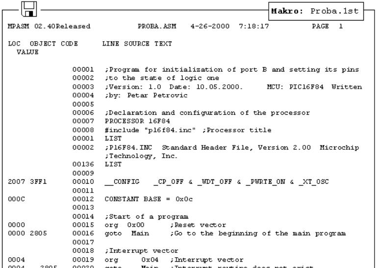
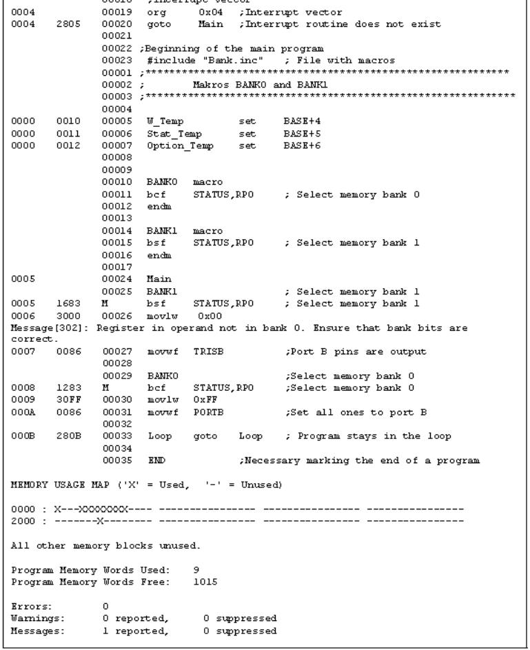
The first file contains translated program which is read in microcontroller by programming. Its contents can not give any information to programmer, so it will not be considered any further. The second file contains possible errors that were made in the process of writing, and which were noticed by assembly translator during translation process. Errors can be discovered in a "list" file as well. This file is more suitable though when program is big and viewing the 'list' file takes longer.
The third file is the most useful to programmer. Much information is contained in it, like information about positioning instructions and variables in memory, or error signalization.
Example of 'list' file for the program in this chapter follows. At the top of each page is found information about the file name, date when it was translated, and page number. First column contains an address in program memory where a instruction from that row is placed. Second column contains a value of any variable defined by one of the directives : SET, EQU, VARIABLE, CONSTANT or CBLOCK. Third column is reserved for the form of a translated instruction which PIC is executing. The fourth column contains assembler instructions and programmer's comments. Possible errors will appear between rows following a line in which the error occured.
http://www.mikroelektronika.co.yu/english/books/4_Poglavlje.htm (16 of 19) [30/12/2001 16:53:53]
Chapter 4 - Assembly Language Programming
At the end of the "list" file there is a table of symbols used in a program. Useful element of 'list'
http://www.mikroelektronika.co.yu/english/books/4_Poglavlje.htm (17 of 19) [30/12/2001 16:53:53]

Chapter 4 - Assembly Language Programming
file is a graph of memory utilization. At the very end, there is an error statistic as well as the amount of remaining program memory.
Macros
Macros are a very useful element in assembly language. They could briefly be described as "user defined group of instructions which will enter assembler program where macro was called". It is possible to write a program even without using macros. But with their use written program is much more legible, especially if more programmers are working on the same program. Macros have the same purpose as functions of complex program languages.
How to write them:
<label> macro [<argument1>,<argument2>,......<argumentN>]
........
.......
endm
From the way they are written, we see that macros can accept arguments, which is also very useful in programming. Whenever argument appears in the body of a macro, it will be replaced with the <argumentN> value.
Example:
The above example shows a macro whose purpose is to place on port B the ARG1 argument that was defined while macro was called. Its use in the program would be limited to writing one line: ON_PORTB 0xFF , and thus we would place value 0xFF on PORTB. In order to use a macro in the program, it is necessary to include macro file in the main program with instruction include "macro_name.inc". Contents of a macro is automatically copied onto a place where this instruction is written. This can be best seen in a previous list file where file with macros is copied below the line #include"bank.inc"
http://www.mikroelektronika.co.yu/english/books/4_Poglavlje.htm (18 of 19) [30/12/2001 16:53:53]
Chapter 4 - Assembly Language Programming
© Copyright 1999. mikroElektronika. All Rights Reserved. For any comments contact webmaster.
http://www.mikroelektronika.co.yu/english/books/4_Poglavlje.htm (19 of 19) [30/12/2001 16:53:53]